Page 1635 of 1903
Downloaded from www.Manualslib.com manuals search engine 3. Remove the storage box.
4. Remove the bolts (1) under the rubber cushion.
5. Remove the lower console.
6. Installation is in the reverse order of removal.
INSTRUMENT PANEL
LTSM150095
LTSM150096
15
15–51Chery Automobile Co., Ltd.
Page 1636 of 1903

Downloaded from www.Manualslib.com manuals search engine INSTRUMENT CLUSTER
Description
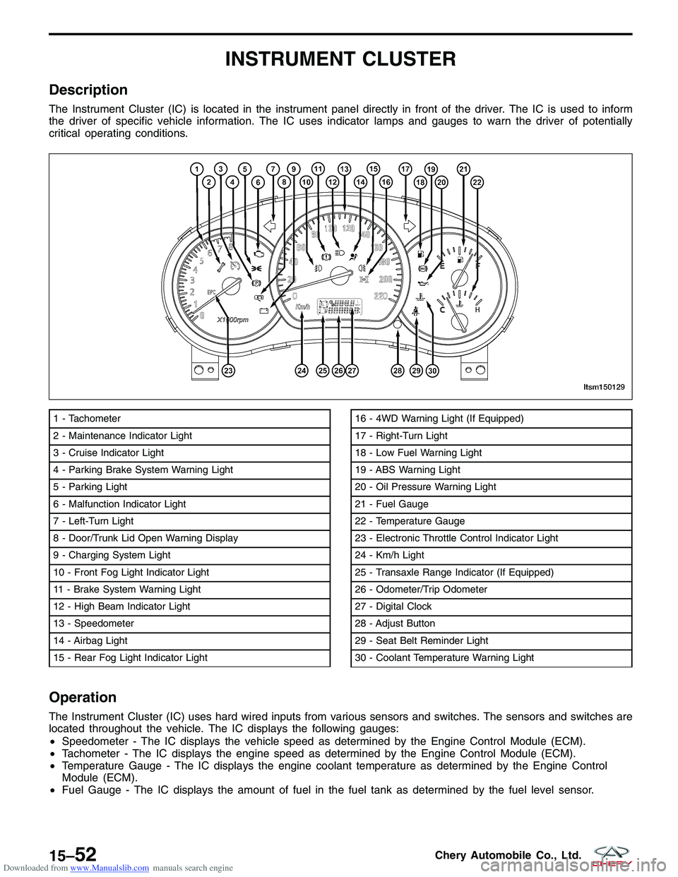
The Instrument Cluster (IC) is located in the instrument panel directly in front of the driver. The IC is used to inform
the driver of specific vehicle information. The IC uses indicator lamps and gauges to warn the driver of potentially
critical operating conditions.
Operation
The Instrument Cluster (IC) uses hard wired inputs from various sensors and switches. The sensors and switches are
located throughout the vehicle. The IC displays the following gauges:
•Speedometer - The IC displays the vehicle speed as determined by the Engine Control Module (ECM).
• Tachometer - The IC displays the engine speed as determined by the Engine Control Module (ECM).
• Temperature Gauge - The IC displays the engine coolant temperature as determined by the Engine Control
Module (ECM).
• Fuel Gauge - The IC displays the amount of fuel in the fuel tank as determined by the fuel level sensor.
1 - Tachometer
2 - Maintenance Indicator Light
3 - Cruise Indicator Light
4 - Parking Brake System Warning Light
5 - Parking Light
6 - Malfunction Indicator Light
7 - Left-Turn Light
8 - Door/Trunk Lid Open Warning Display
9 - Charging System Light
10 - Front Fog Light Indicator Light
11 - Brake System Warning Light
12 - High Beam Indicator Light
13 - Speedometer
14 - Airbag Light
15 - Rear Fog Light Indicator Light16 - 4WD Warning Light (If Equipped)
17 - Right-Turn Light
18 - Low Fuel Warning Light
19 - ABS Warning Light
20 - Oil Pressure Warning Light
21 - Fuel Gauge
22 - Temperature Gauge
23 - Electronic Throttle Control Indicator Light
24 - Km/h Light
25 - Transaxle Range Indicator (If Equipped)
26 - Odometer/Trip Odometer
27 - Digital Clock
28 - Adjust Button
29 - Seat Belt Reminder Light
30 - Coolant Temperature Warning Light
LTSM150129
15–52Chery Automobile Co., Ltd.
Page 1668 of 1903
Downloaded from www.Manualslib.com manuals search engine ON-VEHICLE SERVICE
Instrument Cluster
Removal & Installation
1. Disconnect he negative battery cable.
2. Carefully remove the instrument cluster trim panel.
3. Remove the instrument cluster screws (1).(Tighten: Instrument cluster screws to 5 N·m)
4. Disconnect the instrument cluster electrical connector.
5. Remove the instrument cluster.
6. Installation is in the reverse order of removal.
LTSM150085
15–84Chery Automobile Co., Ltd.
Page 1669 of 1903
Downloaded from www.Manualslib.com manuals search engine INTERIOR LAMPS
Description
The interior lamps consist of the following:
•Key Hole Lamp
• Front Room Lamp
• Middle/Rear Courtesy/Dome Lamp
• Front Step Lamp
• Backlight Adjusting Switch
• Instrument Cluster
• Headlamp Aiming Switch
• Heated Seat Switch (LH)
• Heated Seat Switch (RH)
• Air Control Panel
• Front Fog Lamp Switch
• Rear Fog Lamp Switch
• Console Power Socket (Illumination)
• Door Mirror Remote Control Switch
• Main Power Window And Door Lock/Unlock Switch
• Front Power Window Switch (RH)
• Rear Power Window Switch (LH)
• Rear Power Window Switch (RH)
• Audio
Operation
The key hole lamp and front/middle/rear courtesy lamps are controlled by the BCM. Front step lamps are controlled
by the door lock switch. When the door is open, the front step lamp will light up automatically. Other lamps are
controlled by the lighting and turn signal switch.
15
15–85Chery Automobile Co., Ltd.
Page 1688 of 1903

Downloaded from www.Manualslib.com manuals search engine SEATS
General Information
Description
The seat movement is controlled by an adjustment bar. The seat can be adjusted to six different seating positions.
The vehicle may be equipped with heated seats. Heated seats provide comfort and warmth in cold weather. The
heaters provide the same heat level for both the seat cushion and back. The driver seat and front passenger seat are
heated.
Operation
The manual seat adjustment bar is at the front of the seat, near the floor. Pull the bar upward and slide the seat
forward or rearward. Release the bar once the seat is in the desired position. To confirm the seat is locked into place,
attempt to move the seat forward and rearward after adjusting the seat. The heated seat controls for each seat are
located near the bottom center of the instrument panel. After turning the ignition ON, the seat heater can be activated
to High or Low heat settings. When the switch is in the middle position, the seat heater is OFF. Each switch is
equipped with LED lights to indicate the level of heat at which each seat is set.
15–104Chery Automobile Co., Ltd.
Page 1728 of 1903

Downloaded from www.Manualslib.com manuals search engine ON-VEHICLE SERVICE
Immobilizer Control Module
Removal & Installation
1. Remove the instrument panel (See InstrumentPanel Removal & Installation in Section 15 Body &
Accessory).
2. Remove the steering column mounting bolts.
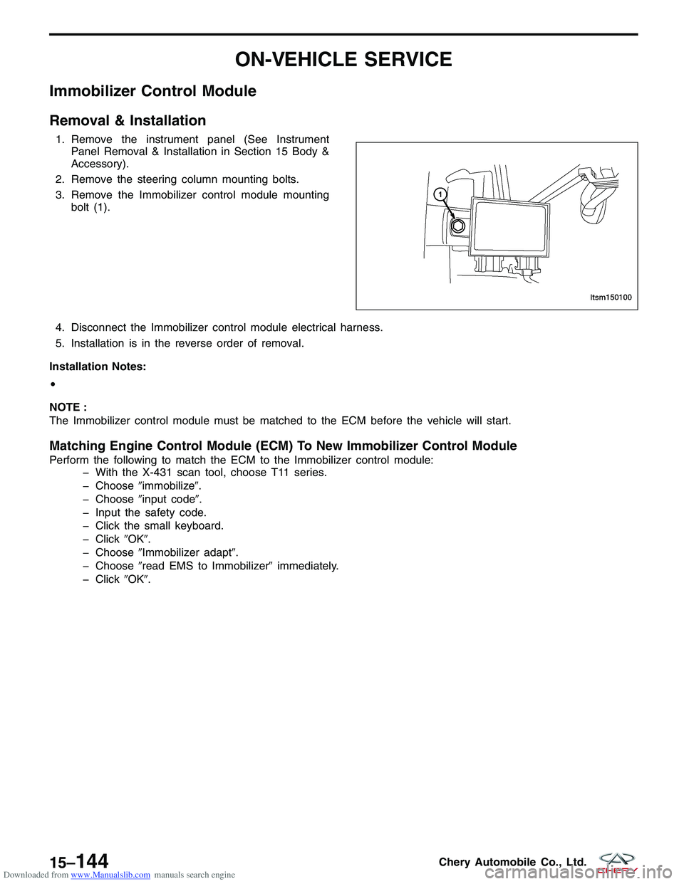
3. Remove the Immobilizer control module mounting bolt (1).
4. Disconnect the Immobilizer control module electrical harness.
5. Installation is in the reverse order of removal.
Installation Notes:
•
NOTE :
The Immobilizer control module must be matched to the ECM before the vehicle will start.
Matching Engine Control Module (ECM) To New Immobilizer Control Module
Perform the following to match the ECM to the Immobilizer control module: � With the X-431 scan tool, choose T11 series.
� Choose �immobilize�.
� Choose �input code�.
� Input the safety code.
� Click the small keyboard.
� Click �OK�.
� Choose �Immobilizer adapt�.
� Choose �read EMS to Immobilizer� immediately.
� Click �OK�.
LTSM150100
15–144Chery Automobile Co., Ltd.
Page 1787 of 1903
Downloaded from www.Manualslib.com manuals search engine Hood Release Cable
Removal & Installation
1. Remove the left lower trim of the instrument panel (See Instrument Panel Removal & Installation in Section 15Body & Accessories).
2. Remove the lining of the left fender (See Fender Removal & Installation in Section 15 Body & Accessories).
3. Remove the radiator support (See Radiator Support Removal & Installation in Section 15 Body & Accessories).
4. Loosen the hood release cable.
5. Remove the hood release cable.
6. Installation is in the reverse order of removal.
HOOD
LTSM150108
15
15–203Chery Automobile Co., Ltd.
Page 1803 of 1903

Downloaded from www.Manualslib.com manuals search engine Front Windshield
Removal
1. Remove the wiper arms and the lower trim panel from the windshield (See Wiper Arm Removal & Installation inSection 15 Body & Accessories).
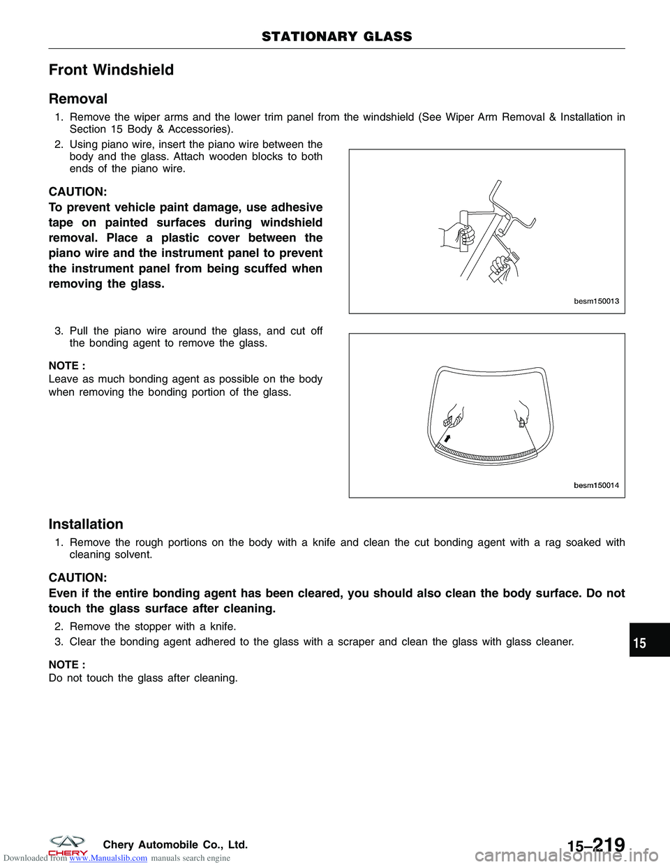
2. Using piano wire, insert the piano wire between the body and the glass. Attach wooden blocks to both
ends of the piano wire.
CAUTION:
To prevent vehicle paint damage, use adhesive
tape on painted surfaces during windshield
removal. Place a plastic cover between the
piano wire and the instrument panel to prevent
the instrument panel from being scuffed when
removing the glass.
3. Pull the piano wire around the glass, and cut offthe bonding agent to remove the glass.
NOTE :
Leave as much bonding agent as possible on the body
when removing the bonding portion of the glass.
Installation
1. Remove the rough portions on the body with a knife and clean the cut bonding agent with a rag soaked with cleaning solvent.
CAUTION:
Even if the entire bonding agent has been cleared, you should also clean the body surface. Do not
touch the glass surface after cleaning.
2. Remove the stopper with a knife.
3. Clear the bonding agent adhered to the glass with a scraper and clean the glass with glass cleaner.
NOTE :
Do not touch the glass after cleaning.
STATIONARY GLASS
BESM150013
BESM150014
15
15–219Chery Automobile Co., Ltd.