2009 CHERY TIGGO tire pressure
[x] Cancel search: tire pressurePage 1415 of 1903

Downloaded from www.Manualslib.com manuals search engine Operation
When the brakes are applied, fluid pressure is exerted against the caliper piston. The fluid pressure is exerted
equally and in all directions. This means pressure exerted against the caliper piston and within the caliper bores will
be equal. Fluid pressure applied to the pistons is transmitted directly to the inboard brake pad. This forces the pad
lining against the inner surface of the brake rotor. At the same time, fluid pressure within the piston bore forces the
caliper to slide inward on the slide pins. This action brings the outboard brake pad lining into contact with the outer
surface of the disc brake rotor.
Removal & Installation
1. Using a brake pedal holding tool, depress the brake pedal past its first 25 mm of travel and hold it in this posi-tion. This will isolate the master cylinder from the brake hydraulic system and will not allow the brake fluid to
drain out of the master cylinder reservoir when the lines are opened.
2. Raise and support the vehicle.
3. Remove the wheel mounting nuts and the tire and wheel assembly. (Tighten: Wheel mounting nuts to 110 N·m)
4. Remove the banjo bolt connecting the brake hose to the rear brake caliper. (Tighten: Rear caliper banjo bolt to 20 N·m)
5. Remove the rear caliper guide pin bolts. (Tighten: Rear caliper guide pin bolts to 23 N·m)
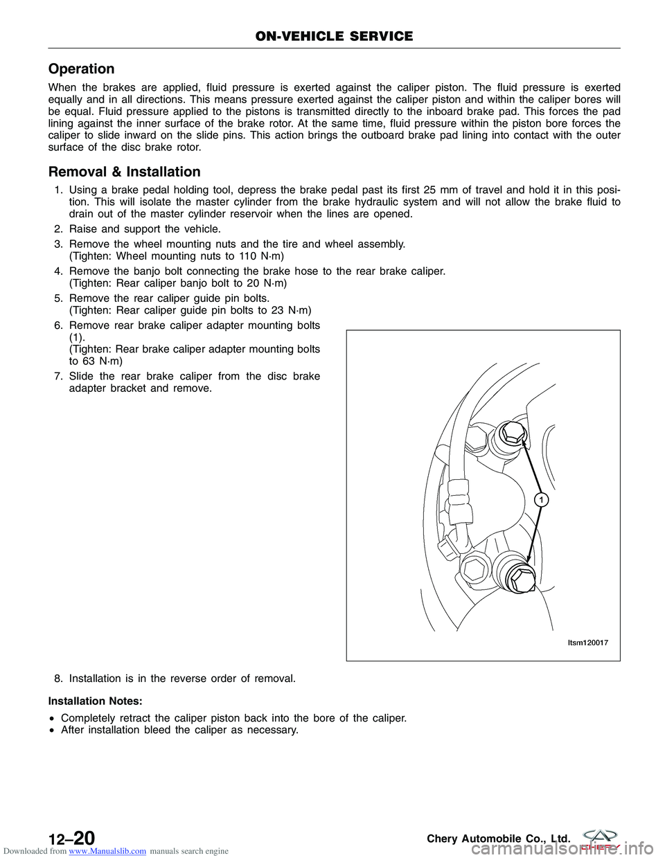
6. Remove rear brake caliper adapter mounting bolts (1).
(Tighten: Rear brake caliper adapter mounting bolts
to 63 N·m)
7. Slide the rear brake caliper from the disc brake adapter bracket and remove.
8. Installation is in the reverse order of removal.
Installation Notes:
• Completely retract the caliper piston back into the bore of the caliper.
• After installation bleed the caliper as necessary.
ON-VEHICLE SERVICE
LTSM120017
12–20Chery Automobile Co., Ltd.
Page 1515 of 1903

Downloaded from www.Manualslib.com manuals search engine GENERAL INFORMATION
Description
The A/C refrigerant lines and pipes are used to carry the refrigerant between the various A/C system components.
Any kinks or sharp bends in the refrigerant lines and hoses will reduce the capacity of the entire A/C system and can
reduce the flow of refrigerant within the system.
Operation
High pressure is produced in a refrigerant system when the A/C compressor is operating. Extreme care must be
exercised to make sure that each of the refrigerant system connections is pressure-tight and leak free. It is a good
practice to inspect all flexible hose refrigerant lines at least once a year to make sure they are in good condition and
properly routed. Depending on vehicle, model and market application, refrigerant lines are connected to each other or
other A/C system components with block-type or quick-connect type fittings. To ensure the integrity of the refrigerant
system, O-rings and/or gaskets may be used to seal the refrigerant system connections. The refrigerant lines and
hoses cannot be repaired and must be replaced if leaking or damaged.
WARNING!
The A/C system contains refrigerant under high pressure. Repairs should only be performed by qualified service
personnel. Serious or fatal injury may result from improper service procedures.
If accidental A/C system discharge occurs, ventilate the work area before resuming service. Large amounts of
refrigerant released in a closed work area will displace the oxygen and cause suffocation and serious or fatal
injury.
CAUTION:
Never add R-12 to a refrigerant system designed to use R-134a. Do not use R-12 equipment or
parts on an R-134a A/C system. These refrigerants are not compatible and damage to the A/C sys-
tem will result.
CAUTION:
Never use R-12 refrigerant oil in an A/C system designed to use R-134a refrigerant oil. These refrig-
erant oils are not compatible and damage to the A/C system will result.
CAUTION:
Do not run the engine with a vacuum pump in operation or with a vacuum present within the A/C
system. Failure to follow this caution will result in serious A/C compressor damage.
CAUTION:
Do not overcharge the refrigerant system. Overcharging will cause excessive compressor head
pressure and can cause compressor noise and A/C system failure.
Specifications
Torque Specifications
DESCRIPTIONTORQUE (N·m)
A/C Compressor Bracket Bolts 40
A/C Compressor Line Bolts 20
13
13–33Chery Automobile Co., Ltd.
Page 1774 of 1903

Downloaded from www.Manualslib.com manuals search engine Headlamp Adjustment Procedure
NOTE :
Follow all local laws and regulations and verify the following items before adjustment:1. Check the following before starting the headlamp adjustment procedure: •All tires are filled to the proper tire pressure.
• The vehicle is unloaded (except for spare tire and tools, and include driver’s weight for sedan).
• The vehicle should be parked on a level surface.
• The headlights are clean.
• The headlights are working properly.
2. Park the vehicle on a level surface approximately 10 meters from the vertical wall or screen directly in front of it. NOTE: The vertical wall or screen must be a minimum of 2.4 meters wide.
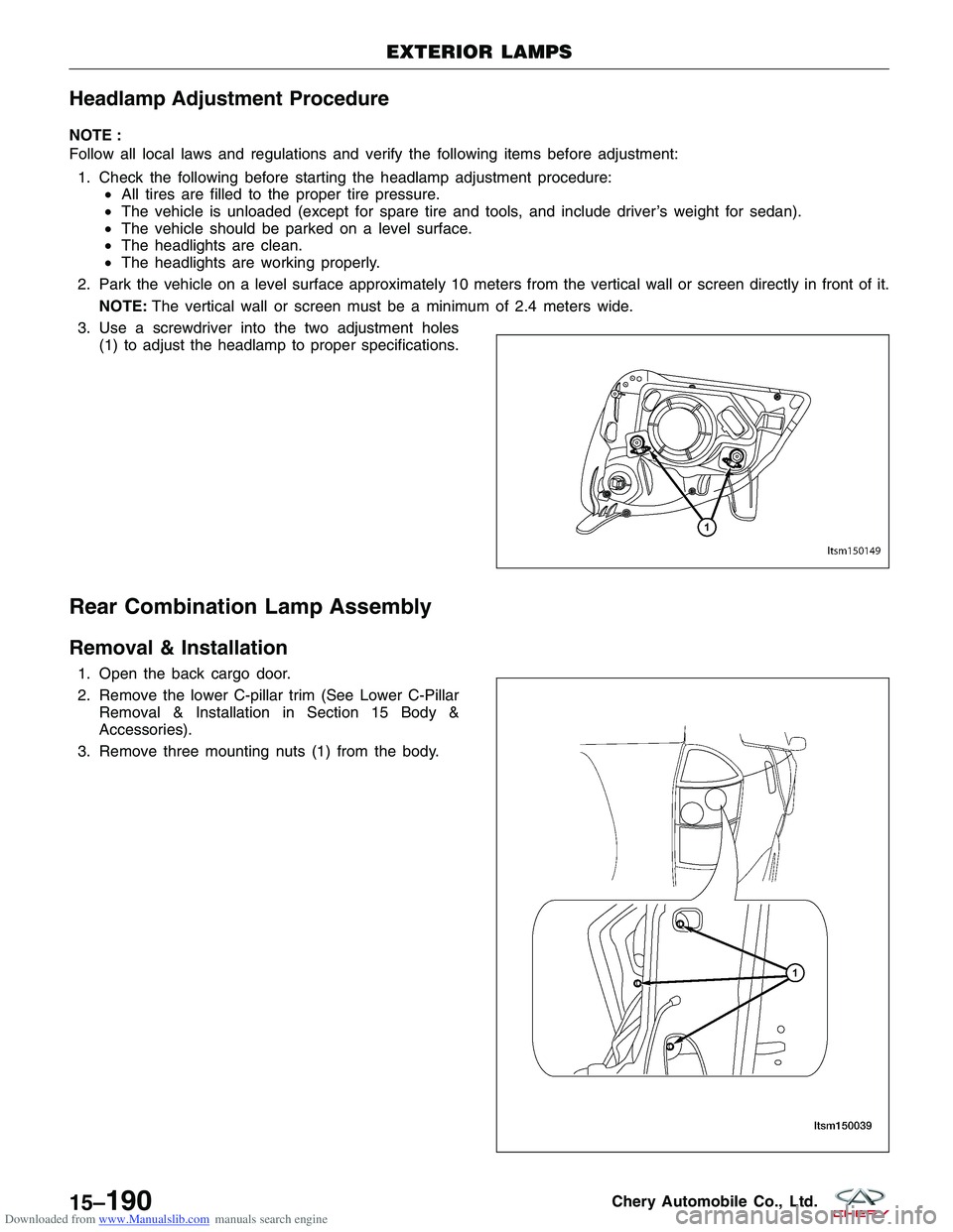
3. Use a screwdriver into the two adjustment holes (1) to adjust the headlamp to proper specifications.
Rear Combination Lamp Assembly
Removal & Installation
1. Open the back cargo door.
2. Remove the lower C-pillar trim (See Lower C-PillarRemoval & Installation in Section 15 Body &
Accessories).
3. Remove three mounting nuts (1) from the body.
EXTERIOR LAMPS
LTSM150149
LTSM150039
15–190Chery Automobile Co., Ltd.
Page 1899 of 1903

Downloaded from www.Manualslib.com manuals search engine Front Strut, Front Suspension..................10-21
Front Sub-Frame Assembly, Front Suspension .......10-17
Front Suspension ........................... 10-1
Front Wheel Alignment, Alignment ...............10-44
Front Wheel Speed Sensor, Antilock Brakes .........12-77
Front Windshield, Body Exterior ................15-219
Front Wiper Arm, Body Exterior ................15-240
Front Wiper Link, Body Exterior ................15-241
Front Wiper Motor, Body Exterior ...............15-238
Fuel Delivery System ..........................4-1
Fuel Door, Body Exterior ..................... 15-200
Fuel Door, Body Exterior ........................200
Fuel Filter, Fuel Delivery System .................4-18
Fuel Injector Rail, Fuel Delivery System ............4-19
Fuel Injector, Fuel Delivery System ................4-20
Fuel Pressure Regulator - With Mitsubishi 2.4L Engine, Fuel Delivery System ..................4-23
Fuel Pressure Relief Procedure, Fuel Delivery System . . . 4-15
Fuel Pump, Fuel Delivery System .................4-15
G
Gear Selector & Shifter Assembly, 5-Speed Manual
Transaxle ............................... 8-264
General Information, 1.6L & 1.8L Engine Controls ......3-3
General Information, 1.6L & 1.8L Engine Mechanical ....2-3
General Information, 2.0L Engine Controls ..........3-229
General Information, 2.0L Engine Mechanical .........2-77
General Information, 2.4L Engine Controls ..........3-442
General Information, 2.4L Engine Mechanical ........2-151
General Information, 5-Speed Manual Transaxle ......8-247
General Information, Air Distribution ..............13-26
General Information, Airbag System ...............14-2
General Information, Alignment .................10-39
General Information, Antilock Brakes .............12-35
General Information, Base Brakes ................12-2
General Information, Body Interior ..............15-104
General Information, Charging System .............5-12
General Information, Clutch System ..............8-317
General Information, Cooling System ...............6-2
General Information, DP0 Automatic Transaxle .........8-3
General Information, Drive Shaft (4x4) .............9-25
General Information, Evaporative Emissions .........3-577
General Information, Exhaust System ...............7-2
General Information, F4A4 Automatic Transaxle ......8-144
General Information, Front Axle ...................9-2
General Information, Front Differential .............8-308General Information, Front Suspension
.............10-2
General Information, Fuel Delivery System ...........4-2
General Information, Ignition Control .............3-566
General Information, Interactive Torque Management (ITM) System (4x4) ...............9-17
General Information, Manual Temperature Control .....13-2
General Information, Parking Brake ..............12-80
General Information, Power Steering Pump .........11-32
General Information, Rear Axle ...................9-9
General Information, Rear Suspension ............10-26
General Information, Seat Belt System ............14-51
General Information, Starting System ...............5-2
General Information, Steering Column .............11-9
General Information, Steering Gear ...............11-19
General Information, Steering System ..............11-2
General Information, System Controls .............13-19
General Information, System Plumbing ............13-33
General Information, T
ransfer Case (4x4)..........8-327
General Information, Vehicle Fuse Box Information ....16-38
General Information, Vehicle Ground Distribution .....16-28
General Information, Vehicle Power Distribution ......16-13
General Information, Vehicle Wiring Harness Layout . . . 16-45
General Information, Wheels and Tires ............10-48
General Information, Wiring Information ............16-2
Generator, Charging System ....................5-17
Grille, Body Exterior ........................ 15-201
Grille, Body Exterior ...........................201
H
Headlamp, Body Exterior ..................... 15-191
Headliner, Body Interior ...................... 15-15
Heated Seat Element, Body Interior ..............15-109
Heated Seat Switch, Body Interior ..............15-109
Heater Core, System Plumbing .................13-47
High Mounted Stop Lamp, Body Exterior ..........15-197
Hood Release Cable, Body Exterior ..............15-203
Hood, Body Exterior ........................ 15-202
Hood, Body Exterior ...........................202
Horn, Body Exterior .................. 15-206, 15-208
How To Locate Electrical Schematics In The Service Manual, Electrical Information ............1-25
How To Read Electrical Schematics, Electrical Information .............................. 1-21
How To Use This Manual, Service Information ........1-2
HVAC Housing, Air Distribution .................13-29
INDEX
AI-4
Page 1901 of 1903

Downloaded from www.Manualslib.com manuals search engine On-Vehicle Service, Interactive Torque Management (ITM)System (4x4) ............................. 9-21
On-Vehicle Service, Manual Temperature Control .....13-15
On-Vehicle Service, Parking Brake ...............12-84
On-Vehicle Service, Power Steering Pump ..........11-34
On-Vehicle Service, Rear Axle ...................9-12
On-Vehicle Service, Rear Suspension .............10-30
On-Vehicle Service, Seat Belt System .............14-52
On-Vehicle Service, Starting System ................5-7
On-Vehicle Service, Steering Column .............11-12
On-Vehicle Service, Steering Gear ...............11-21
On-Vehicle Service, Steering System ..............11-6
On-Vehicle Service, System Controls .............13-24
On-Vehicle Service, System Plumbing .............13-37
On-Vehicle Service, Transfer Case (4x4) ...........8-328
On-Vehicle Service, Wheels and Tires .............10-51
Output Gear For Reverse Gear, 5-Speed Manual Transaxle ......................... 8-296
Output Shaft, 5-Speed Manual Transaxle ...........8-287
Outside Mirror, Body Exterior ..................15-214
Oxygen Sensor, 1.6L & 1.8L Engine Controls .......3-218
Oxygen Sensor, 2.0L Engine Controls .............3-428
Oxygen Sensor, 2.4L Engine Controls .............3-533
P
Paint Codes, Body Exterior ...................15-215
Paint, Body Exterior ........................ 15-215
Parking Brake ............................. 12-79
Parking Brake Cable, Parking Brake ..............12-85
Parking Brake Lever, Parking Brake ..............12-84
Parking Brake Shoes, Parking Brake ..............12-86
Pedal Pad, Body Interior ...................... 15-14
Pistons, 1.6L & 1.8L Engine Mechanical ............2-53
Pistons, 2.0L Engine Mechanical ................2-126
Pistons, 2.4L Engine Mechanical ................2-221
Positive Battery Cable, Starting System .............5-8
Power Brake Booster - LHD, Base Brakes ..........12-14
Power Brake Booster - RHD, Base Brakes ..........12-16
Power Fuse Box, Vehicle Fuse Box Information ......16-38
Power Outlet, Body Interior .................... 15-93
Power Steering Filling and Flushing, Steering System . . . 11-6
Power Steering Fluid Reservoir, Power Steering Pump ........................... 11-36
Power Steering Pressure and Return Lines - 1.6L & 1.8L & 2.0L, Power Steering Pump . . 11-37
Power Steering Pressure and Return Lines - 2.4L, Power Steering Pump ........................... 11-39
Power Steering Pump ....................... 11-31Power Steering Pump - 1.6L & 1.8L & 2.0L,
Power Steering Pump ...................... 11-34
Power Steering Pump - 2.4L, Power Steering Pump . . . 11-35
Power Window Motor, Body Interior .............15-100
Power Window Switch, Body Interior ............15-100
Power Window, Body Interior ..................15-96
Proper Service Practices, Service Information .........1-5
R
Radiator Support, Body Exterior................15-216
Radiator Support, Body Exterior ...................216
Radiator, Cooling System ...................... 6-17
Radio, Body Interior ......................... 15-8
Rear Axle ..................................9-8
Rear Axle Assembly (4x4), Rear Axle ..............9-13
Rear Brake Backing Plate, Base Brakes ............12-23
Rear Brake Caliper, Base Brakes ...........12-19, 12-30
Rear Brake Pads, Base Brakes ..................12-25
Rear Brake Rotor, Base Brakes .................12-22
Rear Coil Spring, Rear Suspension ...............10-33
Rear Combination Lamp Assembly, Body Exterior ....15-190
Rear Crankshaft Oil Seal, 1.6L & 1.8L Engine Mechanical .............................. 2-27
Rear Crankshaft Oil Seal, 2.0L Engine Mechanical ....2-100
Rear Crankshaft Oil Seal, 2.4L Engine Mechanical ....2-179
Rear Door Weatherstrip, Body Exterior ...........15-232
Rear Door, Body Exterior .................... 15-173
Rear Fog Lamp, Body Exterior .................15-193
Rear Hub and Bearing, Rear Axle ................9-12
Rear Intermediate Drive Shaft, Drive Shaft (4x4) ......9-27
Rear Lower Control Arm, Rear Suspension .........10-30
Rear Seat Belt and Pre-Tensioner, Seat Belt System . . . 14-54
Rear Seats, Body Interior .................... 15-107
Rear Shock Absorber, Rear Suspension ...........10-32
Rear Stabilizer Bar Link, Rear Suspension ..........10-32
Rear Suspension ........................... 10-25
Rear Trailing Arm Assembly, Rear Suspension .......10-35
Rear Upper Control Arm, Rear Suspension .........10-31
Rear Wheel Alignment, Alignment ...............10-45
Rear Wheel Speed Sensor, Antilock Brakes .........12-78
Rear Window, Body Exterior ..................15-221
Rear Wiper Arm, Body Exterior ................15-240
Rear Wiper Motor, Body Exterior ...............15-239
Recirculation Door Actuator, System Controls .......13-24
Remote Keyless Entry (RKE) Inoperative, Body Interior ........................... 15-115
Restraints Control Module (RCM), Airbag System .....14-49
INDEX
AI-6