2009 CHERY TIGGO tire pressure
[x] Cancel search: tire pressurePage 1349 of 1903
Downloaded from www.Manualslib.com manuals search engine GENERAL INFORMATION
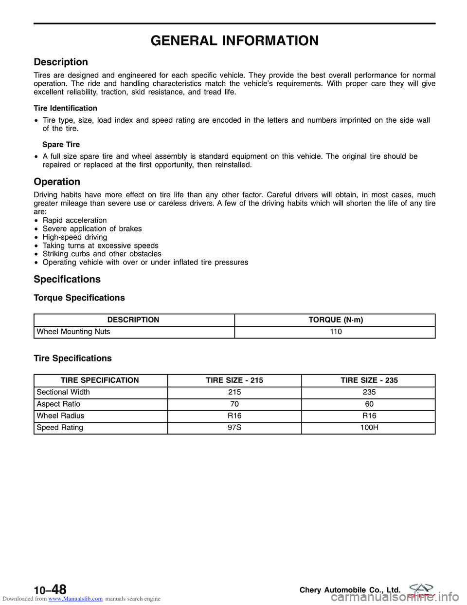
Description
Tires are designed and engineered for each specific vehicle. They provide the best overall performance for normal
operation. The ride and handling characteristics match the vehicle’s requirements. With proper care they will give
excellent reliability, traction, skid resistance, and tread life.
Tire Identification
•Tire type, size, load index and speed rating are encoded in the letters and numbers imprinted on the side wall
of the tire.
Spare Tire
• A full size spare tire and wheel assembly is standard equipment on this vehicle. The original tire should be
repaired or replaced at the first opportunity, then reinstalled.
Operation
Driving habits have more effect on tire life than any other factor. Careful drivers will obtain, in most cases, much
greater mileage than severe use or careless drivers. A few of the driving habits which will shorten the life of any tire
are:
•Rapid acceleration
• Severe application of brakes
• High-speed driving
• Taking turns at excessive speeds
• Striking curbs and other obstacles
• Operating vehicle with over or under inflated tire pressures
Specifications
Torque Specifications
DESCRIPTION TORQUE (N·m)
Wheel Mounting Nuts 110
Tire Specifications
TIRE SPECIFICATIONTIRE SIZE - 215TIRE SIZE - 235
Sectional Width 215235
Aspect Ratio 7060
Wheel Radius R16R16
Speed Rating 97S100H
10–48Chery Automobile Co., Ltd.
Page 1350 of 1903
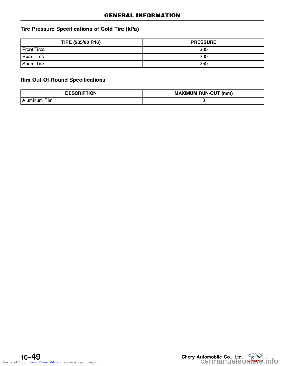
Downloaded from www.Manualslib.com manuals search engine Tire Pressure Specifications of Cold Tire (kPa)
TIRE (235/60 R16)PRESSURE
Front Tires 200
Rear Tires 200
Spare Tire 250
Rim Out-Of-Round Specifications
DESCRIPTIONMAXIMUM RUN-OUT (mm)
Aluminum Rim 3
GENERAL INFORMATION
10–49Chery Automobile Co., Ltd.
Page 1351 of 1903
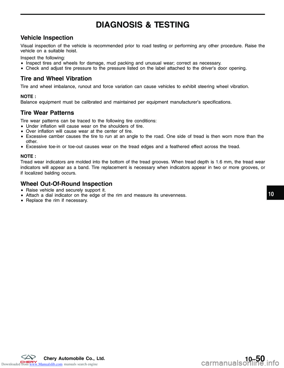
Downloaded from www.Manualslib.com manuals search engine DIAGNOSIS & TESTING
Vehicle Inspection
Visual inspection of the vehicle is recommended prior to road testing or performing any other procedure. Raise the
vehicle on a suitable hoist.
Inspect the following:
•Inspect tires and wheels for damage, mud packing and unusual wear; correct as necessary.
• Check and adjust tire pressure to the pressure listed on the label attached to the driver’s door opening.
Tire and Wheel Vibration
Tire and wheel imbalance, runout and force variation can cause vehicles to exhibit steering wheel vibration.
NOTE :
Balance equipment must be calibrated and maintained per equipment manufacturer’s specifications.
Tire Wear Patterns
Tire wear patterns can be traced to the following tire conditions:
•Under inflation will cause wear on the shoulders of tire.
• Over inflation will cause wear at the center of tire.
• Excessive camber causes the tire to run at an angle to the road. One side of tread is then worn more than the
other.
• Excessive toe-in or toe-out causes wear on the tread edges and a feathered effect across the tread.
NOTE :
Tread wear indicators are molded into the bottom of the tread grooves. When tread depth is 1.6 mm, the tread wear
indicators will appear as a band. Tire replacement is necessary when indicators appear in two or more grooves, or
if localized balding occurs.
Wheel Out-Of-Round Inspection
• Raise vehicle and securely support it.
• Attach a dial indicator on the edge of the rim and measure its unevenness.
• Replace the rim if necessary.10
10–50Chery Automobile Co., Ltd.
Page 1359 of 1903
Downloaded from www.Manualslib.com manuals search engine DIAGNOSIS & TESTING
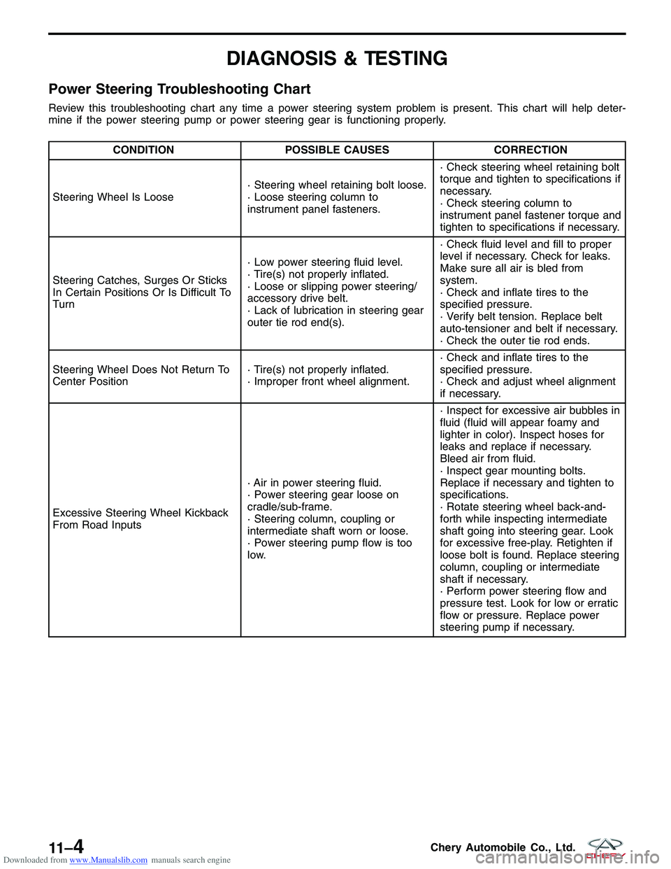
Power Steering Troubleshooting Chart
Review this troubleshooting chart any time a power steering system problem is present. This chart will help deter-
mine if the power steering pump or power steering gear is functioning properly.
CONDITIONPOSSIBLE CAUSES CORRECTION
Steering Wheel Is Loose · Steering wheel retaining bolt loose.
· Loose steering column to
instrument panel fasteners.· Check steering wheel retaining bolt
torque and tighten to specifications if
necessary.
· Check steering column to
instrument panel fastener torque and
tighten to specifications if necessary.
Steering Catches, Surges Or Sticks
In Certain Positions Or Is Difficult To
Turn · Low power steering fluid level.
· Tire(s) not properly inflated.
· Loose or slipping power steering/
accessory drive belt.
· Lack of lubrication in steering gear
outer tie rod end(s).· Check fluid level and fill to proper
level if necessary. Check for leaks.
Make sure all air is bled from
system.
· Check and inflate tires to the
specified pressure.
· Verify belt tension. Replace belt
auto-tensioner and belt if necessary.
· Check the outer tie rod ends.
Steering Wheel Does Not Return To
Center Position · Tire(s) not properly inflated.
· Improper front wheel alignment.· Check and inflate tires to the
specified pressure.
· Check and adjust wheel alignment
if necessary.
Excessive Steering Wheel Kickback
From Road Inputs · Air in power steering fluid.
· Power steering gear loose on
cradle/sub-frame.
· Steering column, coupling or
intermediate shaft worn or loose.
· Power steering pump flow is too
low.· Inspect for excessive air bubbles in
fluid (fluid will appear foamy and
lighter in color). Inspect hoses for
leaks and replace if necessary.
Bleed air from fluid.
· Inspect gear mounting bolts.
Replace if necessary and tighten to
specifications.
· Rotate steering wheel back-and-
forth while inspecting intermediate
shaft going into steering gear. Look
for excessive free-play. Retighten if
loose bolt is found. Replace steering
column, coupling or intermediate
shaft if necessary.
· Perform power steering flow and
pressure test. Look for low or erratic
flow or pressure. Replace power
steering pump if necessary.
11 –4Chery Automobile Co., Ltd.
Page 1366 of 1903
Downloaded from www.Manualslib.com manuals search engine DIAGNOSIS & TESTING
Vehicle Inspection
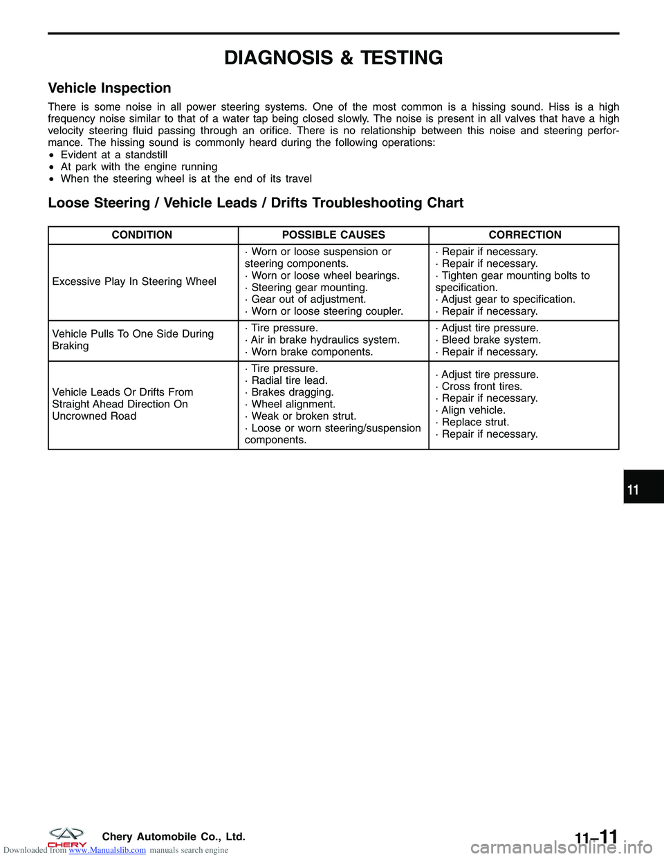
There is some noise in all power steering systems. One of the most common is a hissing sound. Hiss is a high
frequency noise similar to that of a water tap being closed slowly. The noise is present in all valves that have a high
velocity steering fluid passing through an orifice. There is no relationship between this noise and steering perfor-
mance. The hissing sound is commonly heard during the following operations:
•Evident at a standstill
• At park with the engine running
• When the steering wheel is at the end of its travel
Loose Steering / Vehicle Leads / Drifts Troubleshooting Chart
CONDITION POSSIBLE CAUSES CORRECTION
Excessive Play In Steering Wheel · Worn or loose suspension or
steering components.
· Worn or loose wheel bearings.
· Steering gear mounting.
· Gear out of adjustment.
· Worn or loose steering coupler.· Repair if necessary.
· Repair if necessary.
· Tighten gear mounting bolts to
specification.
· Adjust gear to specification.
· Repair if necessary.
Vehicle Pulls To One Side During
Braking · Tire pressure.
· Air in brake hydraulics system.
· Worn brake components.· Adjust tire pressure.
· Bleed brake system.
· Repair if necessary.
Vehicle Leads Or Drifts From
Straight Ahead Direction On
Uncrowned Road · Tire pressure.
· Radial tire lead.
· Brakes dragging.
· Wheel alignment.
· Weak or broken strut.
· Loose or worn steering/suspension
components.· Adjust tire pressure.
· Cross front tires.
· Repair if necessary.
· Align vehicle.
· Replace strut.
· Repair if necessary.
11
11 –11Chery Automobile Co., Ltd.
Page 1375 of 1903
Downloaded from www.Manualslib.com manuals search engine DIAGNOSIS & TESTING
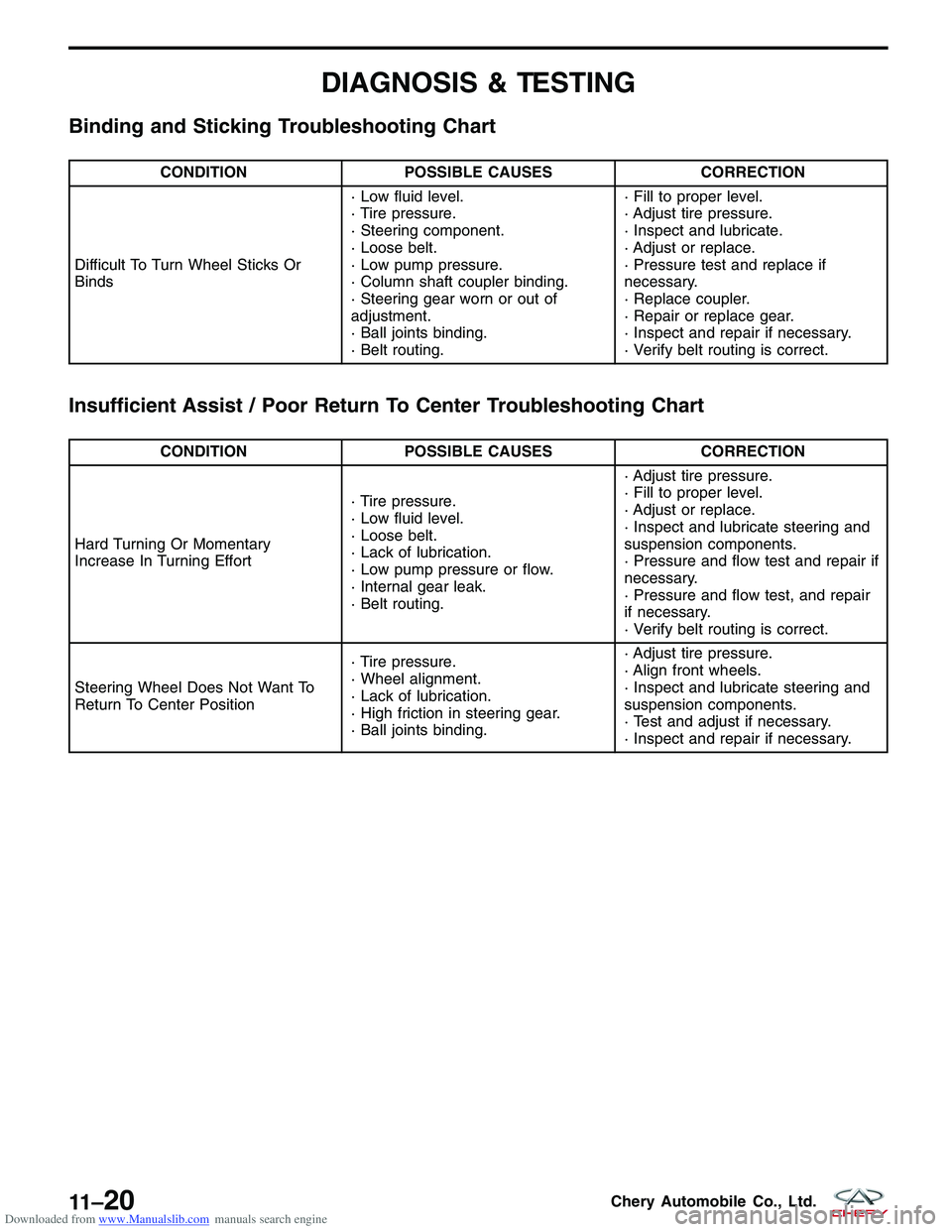
Binding and Sticking Troubleshooting Chart
CONDITIONPOSSIBLE CAUSES CORRECTION
Difficult To Turn Wheel Sticks Or
Binds · Low fluid level.
· Tire pressure.
· Steering component.
· Loose belt.
· Low pump pressure.
· Column shaft coupler binding.
· Steering gear worn or out of
adjustment.
· Ball joints binding.
· Belt routing.· Fill to proper level.
· Adjust tire pressure.
· Inspect and lubricate.
· Adjust or replace.
· Pressure test and replace if
necessary.
· Replace coupler.
· Repair or replace gear.
· Inspect and repair if necessary.
· Verify belt routing is correct.
Insufficient Assist / Poor Return To Center Troubleshooting Chart
CONDITION
POSSIBLE CAUSES CORRECTION
Hard Turning Or Momentary
Increase In Turning Effort · Tire pressure.
· Low fluid level.
· Loose belt.
· Lack of lubrication.
· Low pump pressure or flow.
· Internal gear leak.
· Belt routing.· Adjust tire pressure.
· Fill to proper level.
· Adjust or replace.
· Inspect and lubricate steering and
suspension components.
· Pressure and flow test and repair if
necessary.
· Pressure and flow test, and repair
if necessary.
· Verify belt routing is correct.
Steering Wheel Does Not Want To
Return To Center Position · Tire pressure.
· Wheel alignment.
· Lack of lubrication.
· High friction in steering gear.
· Ball joints binding.· Adjust tire pressure.
· Align front wheels.
· Inspect and lubricate steering and
suspension components.
· Test and adjust if necessary.
· Inspect and repair if necessary.
11 –20Chery Automobile Co., Ltd.
Page 1388 of 1903
Downloaded from www.Manualslib.com manuals search engine DIAGNOSIS & TESTING
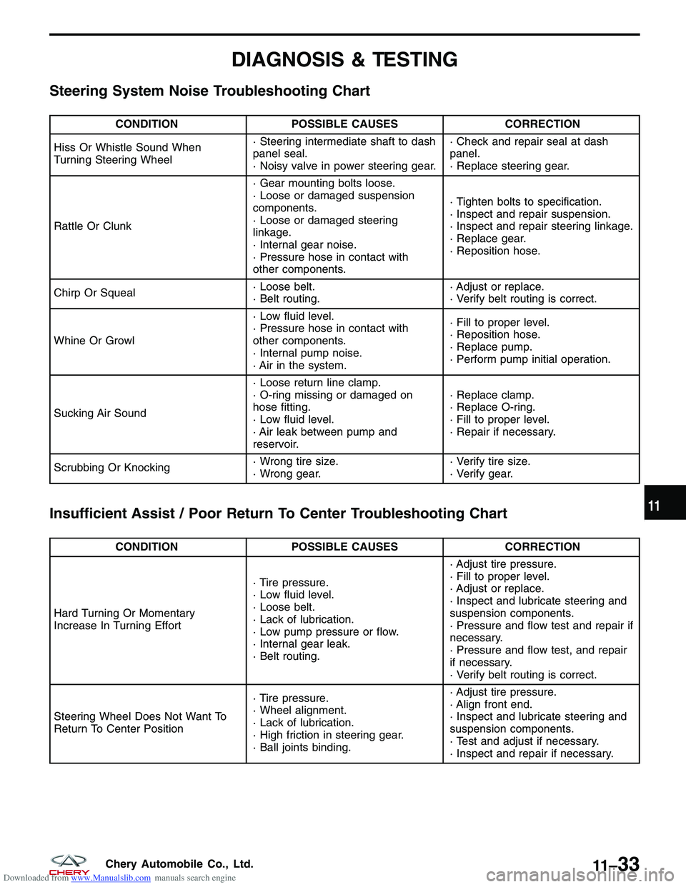
Steering System Noise Troubleshooting Chart
CONDITIONPOSSIBLE CAUSES CORRECTION
Hiss Or Whistle Sound When
Turning Steering Wheel · Steering intermediate shaft to dash
panel seal.
· Noisy valve in power steering gear.· Check and repair seal at dash
panel.
· Replace steering gear.
Rattle Or Clunk · Gear mounting bolts loose.
· Loose or damaged suspension
components.
· Loose or damaged steering
linkage.
· Internal gear noise.
· Pressure hose in contact with
other components.· Tighten bolts to specification.
· Inspect and repair suspension.
· Inspect and repair steering linkage.
· Replace gear.
· Reposition hose.
Chirp Or Squeal · Loose belt.
· Belt routing.· Adjust or replace.
· Verify belt routing is correct.
Whine Or Growl · Low fluid level.
· Pressure hose in contact with
other components.
· Internal pump noise.
· Air in the system.· Fill to proper level.
· Reposition hose.
· Replace pump.
· Perform pump initial operation.
Sucking Air Sound · Loose return line clamp.
· O-ring missing or damaged on
hose fitting.
· Low fluid level.
· Air leak between pump and
reservoir.· Replace clamp.
· Replace O-ring.
· Fill to proper level.
· Repair if necessary.
Scrubbing Or Knocking · Wrong tire size.
· Wrong gear.· Verify tire size.
· Verify gear.
Insufficient Assist / Poor Return To Center Troubleshooting Chart
CONDITION
POSSIBLE CAUSES CORRECTION
Hard Turning Or Momentary
Increase In Turning Effort · Tire pressure.
· Low fluid level.
· Loose belt.
· Lack of lubrication.
· Low pump pressure or flow.
· Internal gear leak.
· Belt routing.· Adjust tire pressure.
· Fill to proper level.
· Adjust or replace.
· Inspect and lubricate steering and
suspension components.
· Pressure and flow test and repair if
necessary.
· Pressure and flow test, and repair
if necessary.
· Verify belt routing is correct.
Steering Wheel Does Not Want To
Return To Center Position · Tire pressure.
· Wheel alignment.
· Lack of lubrication.
· High friction in steering gear.
· Ball joints binding.· Adjust tire pressure.
· Align front end.
· Inspect and lubricate steering and
suspension components.
· Test and adjust if necessary.
· Inspect and repair if necessary.
11
11 –33Chery Automobile Co., Ltd.
Page 1414 of 1903
Downloaded from www.Manualslib.com manuals search engine lining against the inner surface of the disc brake rotor. At the same time, fluid pressure within the piston bore forces
the caliper to slide inward on the slide pins. This action brings the outboard brake pad lining into contact with the
outer surface of the disc brake rotor.
Removal & Installation
1. Using a brake pedal holding tool, depress the brake pedal past its first 25 mm of travel and hold it in this posi-tion. This will isolate the master cylinder from the brake hydraulic system and will not allow the brake fluid to
drain out of the master cylinder reservoir when the lines are opened.
2. Raise and support the vehicle.
3. Remove the wheel mounting nuts and the tire and wheel assembly. (Tighten: Wheel mounting nuts to 110 N·m)
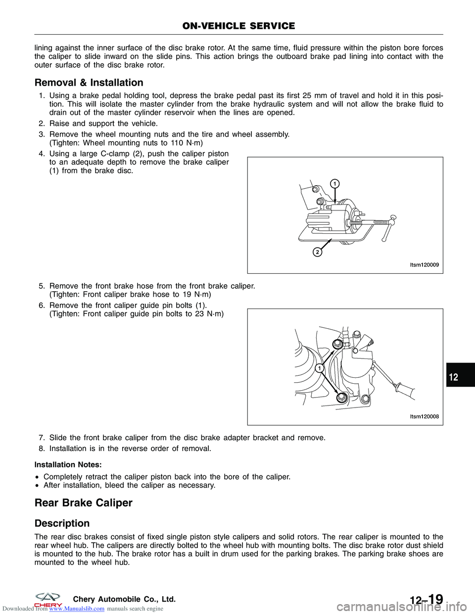
4. Using a large C-clamp (2), push the caliper piston to an adequate depth to remove the brake caliper
(1) from the brake disc.
5. Remove the front brake hose from the front brake caliper. (Tighten: Front caliper brake hose to 19 N·m)
6. Remove the front caliper guide pin bolts (1). (Tighten: Front caliper guide pin bolts to 23 N·m)
7. Slide the front brake caliper from the disc brake adapter bracket and remove.
8. Installation is in the reverse order of removal.
Installation Notes:
• Completely retract the caliper piston back into the bore of the caliper.
• After installation, bleed the caliper as necessary.
Rear Brake Caliper
Description
The rear disc brakes consist of fixed single piston style calipers and solid rotors. The rear caliper is mounted to the
rear wheel hub. The calipers are directly bolted to the wheel hub with mounting bolts. The disc brake rotor dust shield
is mounted to the hub. The brake rotor has a built in drum used for the parking brakes. The parking brake shoes are
mounted to the wheel hub.
ON-VEHICLE SERVICE
LTSM120009
LTSM120008
12
12–19Chery Automobile Co., Ltd.