2009 CHERY TIGGO tire pressure
[x] Cancel search: tire pressurePage 39 of 1903

Downloaded from www.Manualslib.com manuals search engine Flywheel FixtureCH-20043
Engine Hoist
Oil Filter Remover CH-10003
Lubrication System
The engine lubrication system operates as follows:
•Oil is drawn into the oil pump through the oil pump strainer tube in the sump of the oil pan.
• Oil is pumped through the oil filter on the cylinder block.
• Oil enters the main oil gallery where it is distributed to the crankshaft main journals and to the cylinder head.
• From the main journals, the oil is routed through cross-drilled passages in the crankshaft to lubricate the con-
necting rod bearings. Controlled leakage through the crankshaft main bearings and connecting rod bearings is
slung radially outward to cool and lubricate the cylinder walls as well as the entire connecting rod, piston and
piston ring assembly.
• The engine lubrication system is a full-flow filtration, pressure feed type. The oil pump body is mounted to the
engine block. The pump inner rotor is driven by the crankshaft.
Engine Oil Pressure Specifications
Lower Idle Speed (800 ± 50 RPM) 1.2 - 1.5 bar
High Idle Speed (2000 RPM) 3.2 - 3.5 bar
High Speed (4000 RPM) 3.7 ± 0.5 bar
GENERAL INFORMATION
02–10Chery Automobile Co., Ltd.
Page 113 of 1903

Downloaded from www.Manualslib.com manuals search engine Engine Hoist
Flywheel FixtureCH-20043
Oil Filter Remover CH-10003
Lubrication System
The engine lubrication system operates as follows:
•Oil is drawn into the oil pump through the oil pump strainer tube in the sump of the oil pan.
• Oil is pumped through the oil filter on the cylinder block.
• Oil enters the main oil gallery where it is distributed to the crankshaft main journals and to the cylinder head.
• From the main journals, the oil is routed through cross-drilled passages in the crankshaft to lubricate the con-
necting rod bearings. Controlled leakage through the crankshaft main bearings and connecting rod bearings is
slung radially outward to cool and lubricate the cylinder walls as well as the entire connecting rod, piston and
piston ring assembly.
• The engine lubrication system is a full-flow filtration, pressure feed type. The oil pump body is mounted to the
engine block. The pump inner rotor is driven by the crankshaft.
Engine Oil Pressure Specifications
Lower Idle Speed (800 ± 50 RPM) 1.2 - 1.5 bar
High Idle Speed (2000 RPM) 3.2 - 3.5 bar
High Speed (4000 RPM) 3.7 ± 0.5 bar
GENERAL INFORMATION
02–84Chery Automobile Co., Ltd.
Page 1307 of 1903
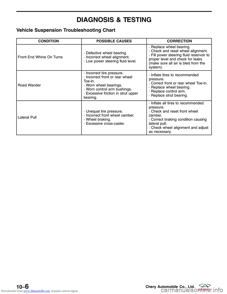
Downloaded from www.Manualslib.com manuals search engine DIAGNOSIS & TESTING
Vehicle Suspension Troubleshooting Chart
CONDITIONPOSSIBLE CAUSES CORRECTION
Front End Whine On Turns · Defective wheel bearing.
· Incorrect wheel alignment.
· Low power steering fluid level.· Replace wheel bearing.
· Check and reset wheel alignment.
· Fill power steering fluid reservoir to
proper level and check for leaks
(make sure all air is bled from the
system).
Road Wander · Incorrect tire pressure.
· Incorrect front or rear wheel
Toe-in.
· Worn wheel bearings.
· Worn control arm bushings.
· Excessive friction in strut upper
bearing.· Inflate tires to recommended
pressure.
· Correct front or rear wheel Toe-in.
· Replace wheel bearing.
· Replace control arm.
· Replace strut bearing.
Lateral Pull · Unequal tire pressure.
· Incorrect front wheel camber.
· Wheel braking.
· Excessive cross-caster.· Inflate all tires to recommended
pressure.
· Check and reset front wheel
camber.
· Correct braking condition causing
lateral pull.
· Check wheel alignment and adjust
as necessary.
10–6Chery Automobile Co., Ltd.
Page 1315 of 1903
Downloaded from www.Manualslib.com manuals search engine Operation
The strut assembly cushions the ride of the vehicle, controlling vibration, jounce and rebound of the suspension. The
coil spring controls ride quality and maintains proper ride height. The spring isolators isolate the coil spring at the top
and bottom from coming into metal-to-metal contact with the upper mounting seat and the strut. The strut dampens
jounce and rebound motions of the coil spring and suspension.
Diagnosis & Testing
Before removing the front strut, perform the following to test the front strut functionality:
•Adjust the tire pressure to all tires to proper specifications.
• Push and shake the front of the vehicle three or four times with identical force every time
• During the pushing and recoiling, the resistance and recoil times of the vehicle should be equal.
• If the strut (shock absorber) functions properly, the vehicle will recoil several times and then stop recoiling after
the pushing force is removed.
Removal & Installation
1. Raise and support the vehicle.
2. Remove the wheel mounting nuts and the wheel assembly.
(Tighten: Wheel mounting nuts to 110 N·m)
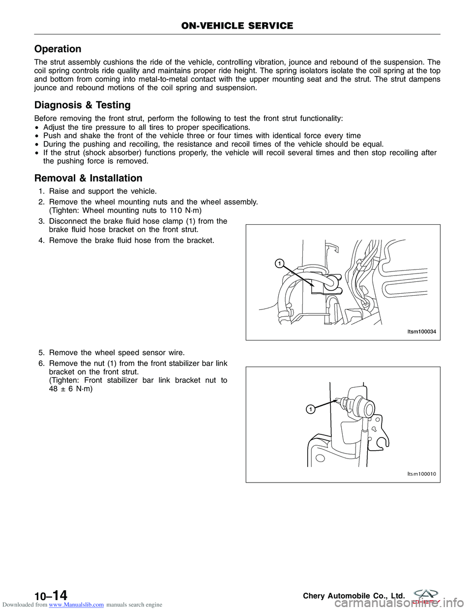
3. Disconnect the brake fluid hose clamp (1) from the brake fluid hose bracket on the front strut.
4. Remove the brake fluid hose from the bracket.
5. Remove the wheel speed sensor wire.
6. Remove the nut (1) from the front stabilizer bar link bracket on the front strut.
(Tighten: Front stabilizer bar link bracket nut to
48 ± 6 N·m)
ON-VEHICLE SERVICE
LTSM100034
LTSM100010
10–14Chery Automobile Co., Ltd.
Page 1340 of 1903
Downloaded from www.Manualslib.com manuals search engine GENERAL INFORMATION
Description
Vehicle wheel alignment is the positioning of all interrelated front and rear suspension angles. These angles affect the
handling and steering of the vehicle when it is in motion. Proper wheel alignment is essential for efficient steering,
good directional stability, and proper tire wear.
The method of checking a vehicle’s front and rear wheel alignment varies depending on the manufacturer and type
of equipment used. The manufacturer’s instructions should always be followed to ensure accuracy of the alignment.
On this vehicle, the suspension angles that can be adjusted are as follows:
Front Axle
•Camber
• Caster
• Toe-in
Rear Axle
• Camber
• Toe-in
Check the wheel alignment and make all wheel alignment adjustments with the vehicle standing at its proper curb
height specification. Curb height is the normal riding height of the vehicle. It is measured from a certain point on the
vehicle to the ground or a designated area while the vehicle is sitting on a flat, level surface.
Operation
Curb Height Measurement
The wheel alignment is to be checked and all alignment adjustments made with the vehicle at its required curb height
specification.
• Vehicle height is to be checked with the vehicle on a flat, level surface, preferably a vehicle alignment rack.
• The tires are to be inflated to the recommended pressure.
• All tires are to be the same size as standard equipment.
• Vehicle height is checked with the fuel tank full of fuel, and no passenger or luggage compartment load.
• Vehicle height is not adjustable.
• If the measurement is not within specifications, inspect the vehicle for bent or weak suspension components.
• Compare the parts tag on the suspect coil spring(s) to the parts book and the vehicle sales code, checking for
a match.
• Once removed from the vehicle, compare the coil spring height to a new or known good coil spring. The
heights should vary if the suspect spring is weak.
NOTE :
Prior to reading the curb height measurement, the front and rear of the vehicle must be jounced to settle the sus-
pension. Induce jounce by pushing down on the center of the bumper (fascia), using care not to damage the vehicle,
moving the vehicle up and down, gradually increasing the suspension travel with each stroke. Release the bumper at
the bottom of each stroke, repeating this action several times. Perform this to both front and rear suspensions an
equal number of times.
Pre-Wheel Alignment Inspection
Before any attempt is made to change or correct the wheel alignment, the following inspection and necessary cor-
rections must be made to the vehicle to ensure proper alignment. 1. Verify the fuel tank is full of fuel. If the fuel tank is not full, the reduction in weight will affect the curb height of the vehicle and the alignment specifications.
2. The passenger and luggage compartments of the vehicle should be free of any load that is not factory equip- ment.
10
10–39Chery Automobile Co., Ltd.
Page 1341 of 1903
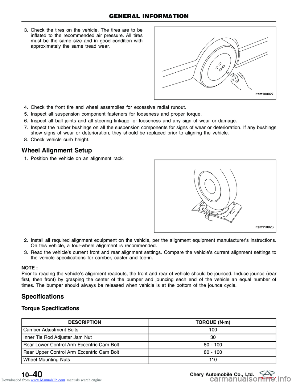
Downloaded from www.Manualslib.com manuals search engine 3. Check the tires on the vehicle. The tires are to beinflated to the recommended air pressure. All tires
must be the same size and in good condition with
approximately the same tread wear.
4. Check the front tire and wheel assemblies for excessive radial runout.
5. Inspect all suspension component fasteners for looseness and proper torque.
6. Inspect all ball joints and all steering linkage for looseness and any sign of wear or damage.
7. Inspect the rubber bushings on all the suspension components for signs of wear or deterioration. If any bushings show signs of wear or deterioration, they should be replaced prior to aligning the vehicle.
8. Check vehicle curb height.
Wheel Alignment Setup
1. Position the vehicle on an alignment rack.
2. Install all required alignment equipment on the vehicle, per the alignment equipment manufacturer’s instructions. On this vehicle, a four-wheel alignment is recommended.
3. Read the vehicle’s current front and rear alignment settings. Compare the vehicle’s current alignment settings to the vehicle specifications for camber, caster and toe-in.
NOTE :
Prior to reading the vehicle’s alignment readouts, the front and rear of vehicle should be jounced. Induce jounce (rear
first, then front) by grasping the center of the bumper and jouncing each end of the vehicle an equal number of
times. The bumper should always be released when vehicle is at the bottom of the jounce cycle.
Specifications
Torque Specifications
DESCRIPTION TORQUE (N·m)
Camber Adjustment Bolts 100
Inner Tie Rod Adjuster Jam Nut 30
Rear Lower Control Arm Eccentric Cam Bolt 80 - 100
Rear Upper Control Arm Eccentric Cam Bolt 80 - 100
Wheel Mounting Nuts 110
GENERAL INFORMATION
LTSM100027
LTSM110026
10–40Chery Automobile Co., Ltd.
Page 1343 of 1903
Downloaded from www.Manualslib.com manuals search engine DIAGNOSIS & TESTING
Vehicle Inspection
Inspect the following for damage:
•Inspect the tires.
• Inspect the rims.
Replace any tire or rim that is found to be damaged.
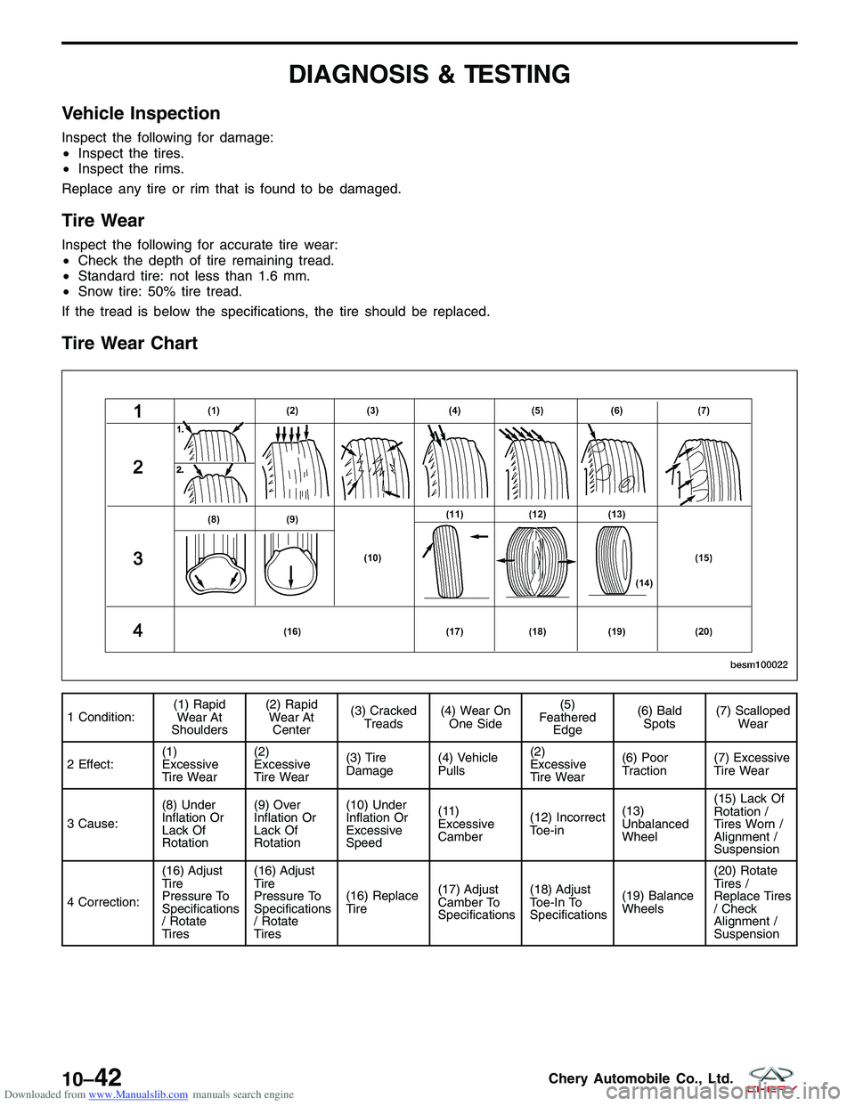
Tire Wear
Inspect the following for accurate tire wear:
• Check the depth of tire remaining tread.
• Standard tire: not less than 1.6 mm.
• Snow tire: 50% tire tread.
If the tread is below the specifications, the tire should be replaced.
Tire Wear Chart
1 Condition: (1) Rapid
Wear At
Shoulders (2) Rapid
Wear At Center (3) Cracked
Treads (4) Wear On
One Side (5)
Feathered Edge (6) Bald
Spots (7) Scalloped
Wear
2 Effect: (1)
Excessive
Tire Wear(2)
Excessive
Tire Wear
(3) Tire
Damage
(4) Vehicle
Pulls(2)
Excessive
Tire Wear(6) Poor
Traction
(7) Excessive
Tire Wear
3 Cause: (8) Under
Inflation Or
Lack Of
Rotation(9) Over
Inflation Or
Lack Of
Rotation(10) Under
Inflation Or
Excessive
Speed
(11)
Excessive
Camber
(12) Incorrect
Toe-in(13)
Unbalanced
Wheel(15) Lack Of
Rotation /
Tires Worn /
Alignment /
Suspension
4 Correction: (16) Adjust
Tire
Pressure To
Specifications
/ Rotate
Tires(16) Adjust
Tire
Pressure To
Specifications
/ Rotate
Tires
(16) Replace
Tire
(17) Adjust
Camber To
Specifications(18) Adjust
Toe-In To
Specifications
(19) Balance
Wheels(20) Rotate
Tires /
Replace Tires
/ Check
Alignment /
Suspension
BESM100022
10–42Chery Automobile Co., Ltd.
Page 1344 of 1903
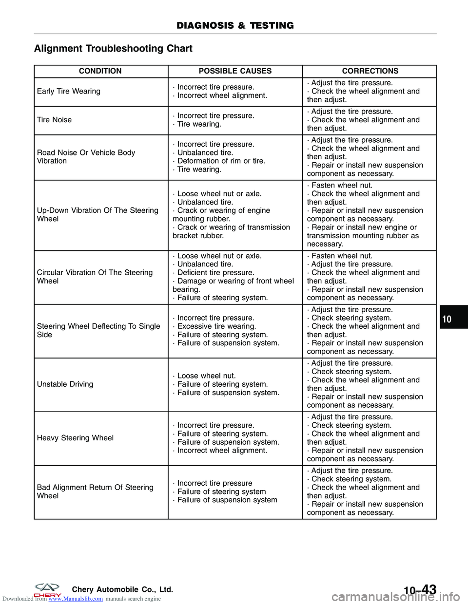
Downloaded from www.Manualslib.com manuals search engine Alignment Troubleshooting Chart
CONDITIONPOSSIBLE CAUSES CORRECTIONS
Early Tire Wearing · Incorrect tire pressure.
· Incorrect wheel alignment.· Adjust the tire pressure.
· Check the wheel alignment and
then adjust.
Tire Noise · Incorrect tire pressure.
· Tire wearing.· Adjust the tire pressure.
· Check the wheel alignment and
then adjust.
Road Noise Or Vehicle Body
Vibration · Incorrect tire pressure.
· Unbalanced tire.
· Deformation of rim or tire.
· Tire wearing.· Adjust the tire pressure.
· Check the wheel alignment and
then adjust.
· Repair or install new suspension
component as necessary.
Up-Down Vibration Of The Steering
Wheel · Loose wheel nut or axle.
· Unbalanced tire.
· Crack or wearing of engine
mounting rubber.
· Crack or wearing of transmission
bracket rubber.· Fasten wheel nut.
· Check the wheel alignment and
then adjust.
· Repair or install new suspension
component as necessary.
· Repair or install new engine or
transmission mounting rubber as
necessary.
Circular Vibration Of The Steering
Wheel · Loose wheel nut or axle.
· Unbalanced tire.
· Deficient tire pressure.
· Damage or wearing of front wheel
bearing.
· Failure of steering system.· Fasten wheel nut.
· Adjust the tire pressure.
· Check the wheel alignment and
then adjust.
· Repair or install new suspension
component as necessary.
Steering Wheel Deflecting To Single
Side · Incorrect tire pressure.
· Excessive tire wearing.
· Failure of steering system.
· Failure of suspension system.· Adjust the tire pressure.
· Check steering system.
· Check the wheel alignment and
then adjust.
· Repair or install new suspension
component as necessary.
Unstable Driving · Loose wheel nut.
· Failure of steering system.
· Failure of suspension system.· Adjust the tire pressure.
· Check steering system.
· Check the wheel alignment and
then adjust.
· Repair or install new suspension
component as necessary.
Heavy Steering Wheel · Incorrect tire pressure.
· Failure of steering system.
· Failure of suspension system.
· Incorrect wheel alignment.· Adjust the tire pressure.
· Check steering system.
· Check the wheel alignment and
then adjust.
· Repair or install new suspension
component as necessary.
Bad Alignment Return Of Steering
Wheel · Incorrect tire pressure
· Failure of steering system
· Failure of suspension system· Adjust the tire pressure.
· Check steering system.
· Check the wheel alignment and
then adjust.
· Repair or install new suspension
component as necessary.
DIAGNOSIS & TESTING
10
10–43Chery Automobile Co., Ltd.