2009 CHERY TIGGO check engine light
[x] Cancel search: check engine lightPage 828 of 1903

Downloaded from www.Manualslib.com manuals search engine Symptom Diagnostic Tests
General Troubleshooting Checks
•Confirm the engine trouble light is working properly.
• Confirm that there are no DTCs recorded with the X-431 Scan Tool.
• Confirm that the customer’s complaint is current, and the conditions that are causing the failure are present.
Visual Inspection
•Check the fuel system for any fuel leakage.
• Check the vacuum system for any broken, kinked or incorrectly linked vacuum pipes or hoses.
• Check the intake air pipe for being jammed, leaking, or damaged.
• Check the ignition system for any broken or aging spark plug wires and verify the engine firing order is correct.
• Check the engine ground cable and verify a clean and tight connection.
• Check the sensors and actuators electrical connectors and verify good contact and tight connection.
NOTE :
Repair any of the above conditions first before continuing with symptom diagnostics.
Diagnostic Help
• Confirm there are no current engine DTCs.
• Confirm that the failure exists and the customer complaint can be verified.
• Inspect the engine following the above steps and verify all engine features are operating properly.
• While servicing the vehicle, verify the service record, vehicle maintenance, engine compression pressures,
mechanical ignition timing and fuel conditions.
• If replacing the Engine Control Module (ECM), carry out the validation test. If the failure no longer exists, the
failure is in the ECM; if the failure still exists, reinstall the original ECM and repeat the diagnostic test.
Symptom Diagnostic Test List
SYMPTOM DEFINITION
Engine Cranks Normal But Will Not Start
Engine Will Not Crank
Hard Start / Long Crank Time
Fast Idle
Lack / Loss Of Power
Back Fires
Engine Poor Driveability
Low Idle / Stalls During Deceleration
Idle Speed Slow Return To Normal Idle
ELECTRONIC ENGINE CONTROLS - 2.4L ENGINE SYMPTOM DIAGNOSIS
03–544Chery Automobile Co., Ltd.
Page 889 of 1903

Downloaded from www.Manualslib.com manuals search engine 4. Remove the fuel pump cover (1).
5. Disconnect the fuel pump connector (3) and thefuel delivery hose (2) and fuel return hose (1).
6. Using special tool CH-20032, remove the fuel pump mounting cover (4).
7. Pull the fuel pump up and out of the fuel tank.
WARNING!
Do not smoke, carry lighted tobacco or have an open flame of any type when working on or near any fuel-
related component. Highly flammable mixtures are always present and may be ignited. Failure to follow these
instructions may result in serious personal injury or death.
Do not carry personal electronic devices such as cell phones, pagers or audio equipment of any type when
working on or near any fuel-related component. Highly flammable mixtures are always present and may be
ignited. Failure to follow these instructions may result in serious personal injury or death.
When handling fuel, always observe fuel handling precautions and be prepared in the event of fuel spillage.
Spilled fuel may be ignited by hot vehicle components or other ignition sources. Failure to follow these instruc-
tions may result in serious personal injury or death.
NOTE :
Make sure not to spill fuel inside of the vehicle. 8. Tip the fuel pump on its side and drain the fuel from the fuel pump and remove the fuel pump from the vehicle. NOTE: To keep the fuel tank portion clean and to avoid damage and foreign materials, cover them completely
with plastic bags or something similar.
9. Remove and discard the seal from the fuel tank.
10. Installation is in the reverse order of removal.
Installation Notes:
• Install a new seal to the fuel pump sealing surface.
• Turn the ignition switch to ON (without starting the engine) to apply fuel pressure to the fuel system, then
check the connections for fuel leaks.
• Start the engine and let it idle and check for fuel leaks at the fuel system connections.
ON-VEHICLE SERVICE
LTSM040001
LTSM040002
04–16Chery Automobile Co., Ltd.
Page 926 of 1903

Downloaded from www.Manualslib.com manuals search engine DIAGNOSIS AND TESTING
Cooling System Pressure Test
WARNING!
Always allow the engine to cool before opening the cooling system. Do not remove the coolant pressure relief
cap when the engine is operating or the cooling system is hot. The cooling system is under pressure; steam and
hot liquid can come out forcefully when the cap is loosened slightly. Failure to follow these instructions may
result in serious personal injury.
CAUTION:
Do not pressurize the cooling system beyond the maximum pressure listed in the specifications
table in this section, or cooling system components can be damaged.
1. Turn the engine off.
2. Check the engine coolant level. Adjust the coolant level as necessary.
3. Attach the pressure tester to the coolant recovery reservoir. Install a pressure test pump to the quick-connectfitting of the test adapter.
4. Pressurize the engine cooling system to 111 kPa. Observe the gauge reading for approximately 2 minutes. Pres- sure should not drop during this time. If the pressure drops within this time, inspect for leaks and repair as nec-
essary.
5. If no leaks are found and the pressure drops, the pressure relief cap may be leaking. Install a new pressure relief cap and retest the system.
6. If no leaks are found after a new pressure relief cap is installed, and the pressure drops, the leak may be inter- nal to the radiator transmission cooler (if equipped). Inspect the coolant for transmission fluid and the transmis-
sion fluid for coolant. Repair as necessary.
7. If there is no contamination of the coolant or transmission fluid, the leak may be internal to the engine. Inspect the coolant for engine oil and the engine oil for coolant.
8. Release the system pressure by loosening the pressure relief cap. Check the coolant level and adjust as nec- essary.
Cooling System Concentration Test
CAUTION:
Do not mix types of coolant, corrosion protection will be severely reduced.
Coolant concentration should be checked when any additional coolant is added to the cooling system or after a cool-
ant drain, flush and refill. The coolant mixture offers optimum engine cooling and protection against corrosion when
mixed to a freeze point of -37°C to -46°C. The use of a hydrometer or a refractometer can be used to test coolant
concentration.
06
06–11Chery Automobile Co., Ltd.
Page 932 of 1903

Downloaded from www.Manualslib.com manuals search engine Removal & Installation - 2.4L
WARNING!
Always allow the engine to cool before opening the cooling system. Do not remove the coolant pressure relief
cap when the engine is operating or the cooling system is hot. The cooling system is under pressure; steam and
hot liquid can come out forcefully when the cap is loosened slightly. Failure to follow these instructions may
result in serious personal injury.
1. Drain the cooling system (See Cooling System Draining Procedure in Section 06 Cooling System).
2. Remove the accessory drive belt (See Accessory Drive Belt Removal & Installation in Section 02 Engine).
3. Remove the engine timing belt (See Engine Timing Belt Removal & Installation in Section 02 Engine).
4. Remove the upper balance shaft timing belt (See Upper Balance Shaft Timing Belt Removal & Installation inSection 02 Engine).
5. Remove the coolant pump mounting bolts (1). (Tighten: Coolant pump mounting bolts to 14 N·m)
6. Remove the coolant pump and gasket.
7. Installation is in the reverse order of removal.
Installation Notes:
• Install a new coolant pump gasket during installation.
• Verify the cooling system is filled to proper specifications.
Coolant Pump Inspection
Check coolant seal of the coolant pump for coolant leak. If coolant pump bearing is loose, replace the assembly.
Radiator
Description
The radiator is a cross-flow type (horizontal tubes) with design features that provide greater strength, as well as
sufficient heat transfer capabilities to keep the engine coolant within operating temperatures.
Operation
The radiator functions as a heat exchanger, using air flow across the exterior of the radiator tubes. Heat from the
coolant is then transferred from the radiator into the moving air.
Removal & Installation
WARNING!
Always allow the engine to cool before opening the cooling system. Do not remove the coolant pressure relief
cap when the engine is operating or the cooling system is hot. The cooling system is under pressure; steam and
hot liquid can come out forcefully when the cap is loosened slightly. Failure to follow these instructions may
result in serious personal injury.
ON-VEHICLE SERVICE
LTSM060003
06
06–17Chery Automobile Co., Ltd.
Page 1212 of 1903

Downloaded from www.Manualslib.com manuals search engine 10. Align the selector finger (1) and fork shaft springpin (2), install the spring pin of selector finger (as
shown by the arrow in the figure).
11. Tighten the interlock plate limit bolt (1) together with the shim to the housing (as shown in the fig-
ure). The tightening torque of the bolt is 30 N·m.
Check front end circular cylinder of the bolt to
ensure it is in the corresponding groove of selector
finger.
12. Check the gearshift shaft to ensure it is able to rotate and perform axial movement freely.
13. Install air duct (1) and air duct cap (2). Apply seal- ant to the surface of the inserted part of air duct.
14. Install the backup light switch assembly (1). (Tighten: Backup light switch to 32 N·m)
ON-VEHICLE SERVICE
LTSM080094
LTSM080128
LTSM080134
LTSM080135
08
08–269Chery Automobile Co., Ltd.
Page 1241 of 1903

Downloaded from www.Manualslib.com manuals search engine Assemble
Assemble in the reverse order of disassembly.
NOTE :
•Check and ensure the shift fork is properly installed to the fork shaft, there should be NO axial or radial motion in
the fork shaft.
• Check and ensure the fork rack is properly installed to the fork shaft, there should be NO axial or radial motion in
the fork shaft.
• Check and ensure backup light driving block is properly installed to the fork shaft, there should be NO axial or
radial motion in the fork shaft.
• Check the fork shaft surface for any damage.
• Check the position of the three spring pins, ensure the pins are in proper alignment. The extension of both ends
of the three spring pins should not exceed 3 mm.
3rd-4th Gear Shift Fork
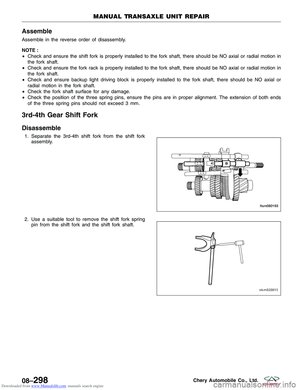
Disassemble
1. Separate the 3rd-4th shift fork from the shift fork
assembly.
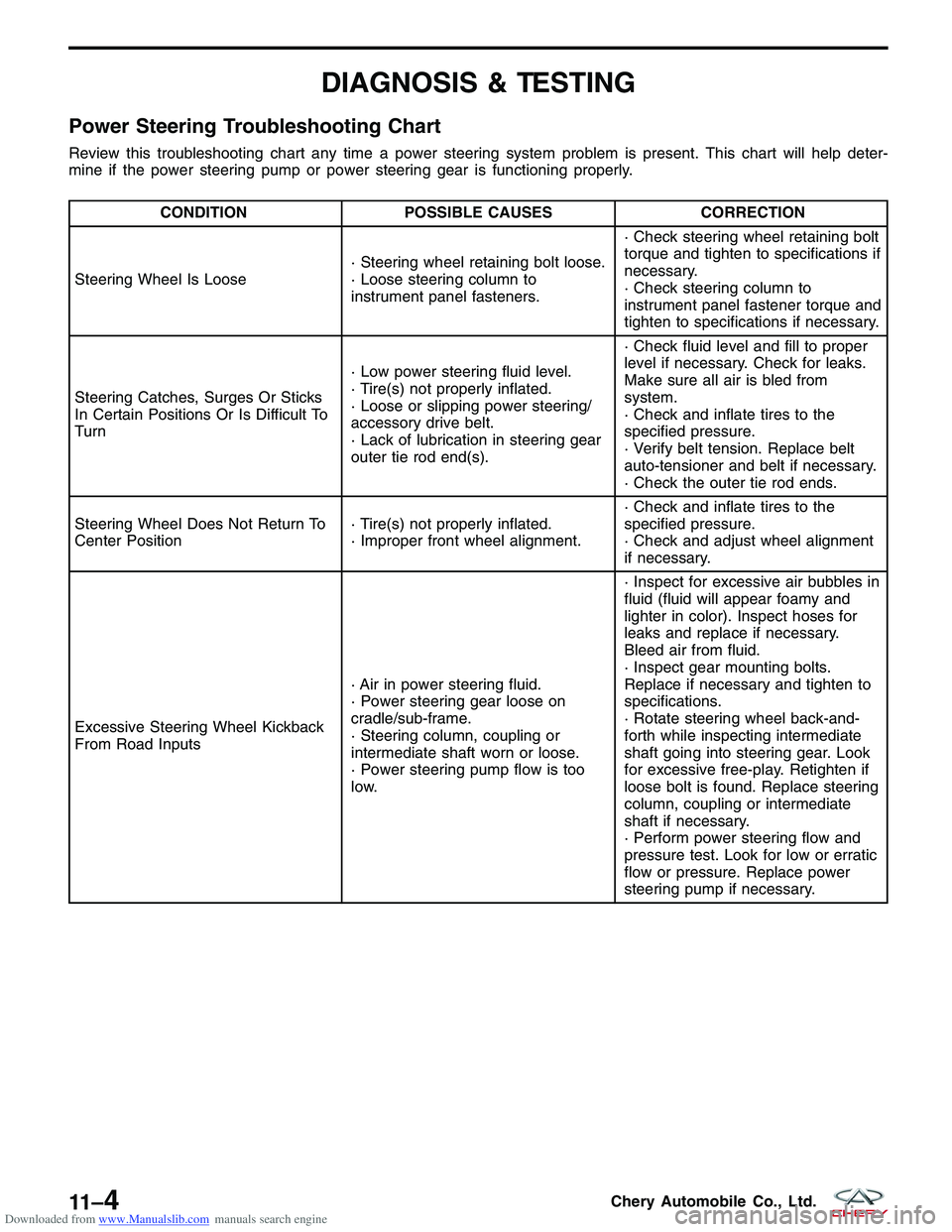
2. Use a suitable tool to remove the shift fork spring pin from the shift fork and the shift fork shaft.
MANUAL TRANSAXLE UNIT REPAIR
LTSM080193
VISM020015
08–298Chery Automobile Co., Ltd.
Page 1359 of 1903

Downloaded from www.Manualslib.com manuals search engine DIAGNOSIS & TESTING
Power Steering Troubleshooting Chart
Review this troubleshooting chart any time a power steering system problem is present. This chart will help deter-
mine if the power steering pump or power steering gear is functioning properly.
CONDITIONPOSSIBLE CAUSES CORRECTION
Steering Wheel Is Loose · Steering wheel retaining bolt loose.
· Loose steering column to
instrument panel fasteners.· Check steering wheel retaining bolt
torque and tighten to specifications if
necessary.
· Check steering column to
instrument panel fastener torque and
tighten to specifications if necessary.
Steering Catches, Surges Or Sticks
In Certain Positions Or Is Difficult To
Turn · Low power steering fluid level.
· Tire(s) not properly inflated.
· Loose or slipping power steering/
accessory drive belt.
· Lack of lubrication in steering gear
outer tie rod end(s).· Check fluid level and fill to proper
level if necessary. Check for leaks.
Make sure all air is bled from
system.
· Check and inflate tires to the
specified pressure.
· Verify belt tension. Replace belt
auto-tensioner and belt if necessary.
· Check the outer tie rod ends.
Steering Wheel Does Not Return To
Center Position · Tire(s) not properly inflated.
· Improper front wheel alignment.· Check and inflate tires to the
specified pressure.
· Check and adjust wheel alignment
if necessary.
Excessive Steering Wheel Kickback
From Road Inputs · Air in power steering fluid.
· Power steering gear loose on
cradle/sub-frame.
· Steering column, coupling or
intermediate shaft worn or loose.
· Power steering pump flow is too
low.· Inspect for excessive air bubbles in
fluid (fluid will appear foamy and
lighter in color). Inspect hoses for
leaks and replace if necessary.
Bleed air from fluid.
· Inspect gear mounting bolts.
Replace if necessary and tighten to
specifications.
· Rotate steering wheel back-and-
forth while inspecting intermediate
shaft going into steering gear. Look
for excessive free-play. Retighten if
loose bolt is found. Replace steering
column, coupling or intermediate
shaft if necessary.
· Perform power steering flow and
pressure test. Look for low or erratic
flow or pressure. Replace power
steering pump if necessary.
11 –4Chery Automobile Co., Ltd.
Page 1402 of 1903

Downloaded from www.Manualslib.com manuals search engine DIAGNOSIS & TESTING
Diagnostic Help
Brake diagnosis involves determining if the concern is related to a mechanical, hydraulic, electrical or vacuum oper-
ated component.
NOTE :
The brake reservoir fluid level will decrease in proportion to normal lining wear.
NOTE :
Brake fluid tends to darken over time. This is normal and should not be mistaken for contamination.
Preliminary Brake Check:
•Check the condition of the tires and wheels. Damaged wheels and worn, damaged or under inflated tires can
cause a pull, shudder, vibration and a condition similar to brake grab.
• If a complaint was based on noise while braking, check the suspension components. Jounce the front and the
rear of vehicle and listen for anything that might be caused by a loose, worn or damaged suspension or steer-
ing component.
• Inspect the brake fluid level and condition.
1. If the fluid level is abnormally low, look for any evidence of leaks at the calipers, brake lines, master cyl-
inder and at the Antilock Brake System (ABS) Hydraulic Control Unit (HCU).
2. If the fluid appears to be contaminated, drain a sample to examine.
• The system will have to be flushed if the fluid is separated into layers, or contains a substance other than
brake fluid. The system seals, cups, hoses, master cylinder and HCU will also have to be replaced after flush-
ing. Use clean brake fluid to flush the system.
• Check the parking brake operation. Verify free movement and full release of the cables and the lever. Also note
if the vehicle was being operated with the parking brake partially applied.
• Check the brake pedal operation. Verify that the pedal does not bind and has adequate free play. If the pedal
lacks free play, check the pedal and the power booster for looseness or for a binding condition. DO NOT road
test the vehicle until the condition is located and corrected.
• Check the vacuum booster check valve and vacuum supply hose.
• If the preliminary checks appear to be OK, road test the vehicle.
Brake Noise
CONDITION POSSIBLE CAUSES CORRECTION
Disc Brake Chirp · Excessive brake rotor runout.
· Small particles· Diagnose and correct as
necessary.
Disc Brake Rattle Or Clunk · Broken or missing spring clips.
· Caliper guide pin bolts loose.
· Missing abutment shims.
· Small metal particles· Replace brake pads.
· Tighten guide pin bolts.
· Replace missing abutment shims.
Disc Brake Squeak At Low Speed
(While Applying Light Brake Pedal
Effort) · Brake shoe linings.
· Replace brake pads.
Scraping Or Whirring · ABS wheel speed sensor hitting
tone wheel.· Inspect, correct or replace faulty
component(s).
12
12–7Chery Automobile Co., Ltd.