2009 CHERY TIGGO check engine light
[x] Cancel search: check engine lightPage 1417 of 1903
Downloaded from www.Manualslib.com manuals search engine Rotor Runout
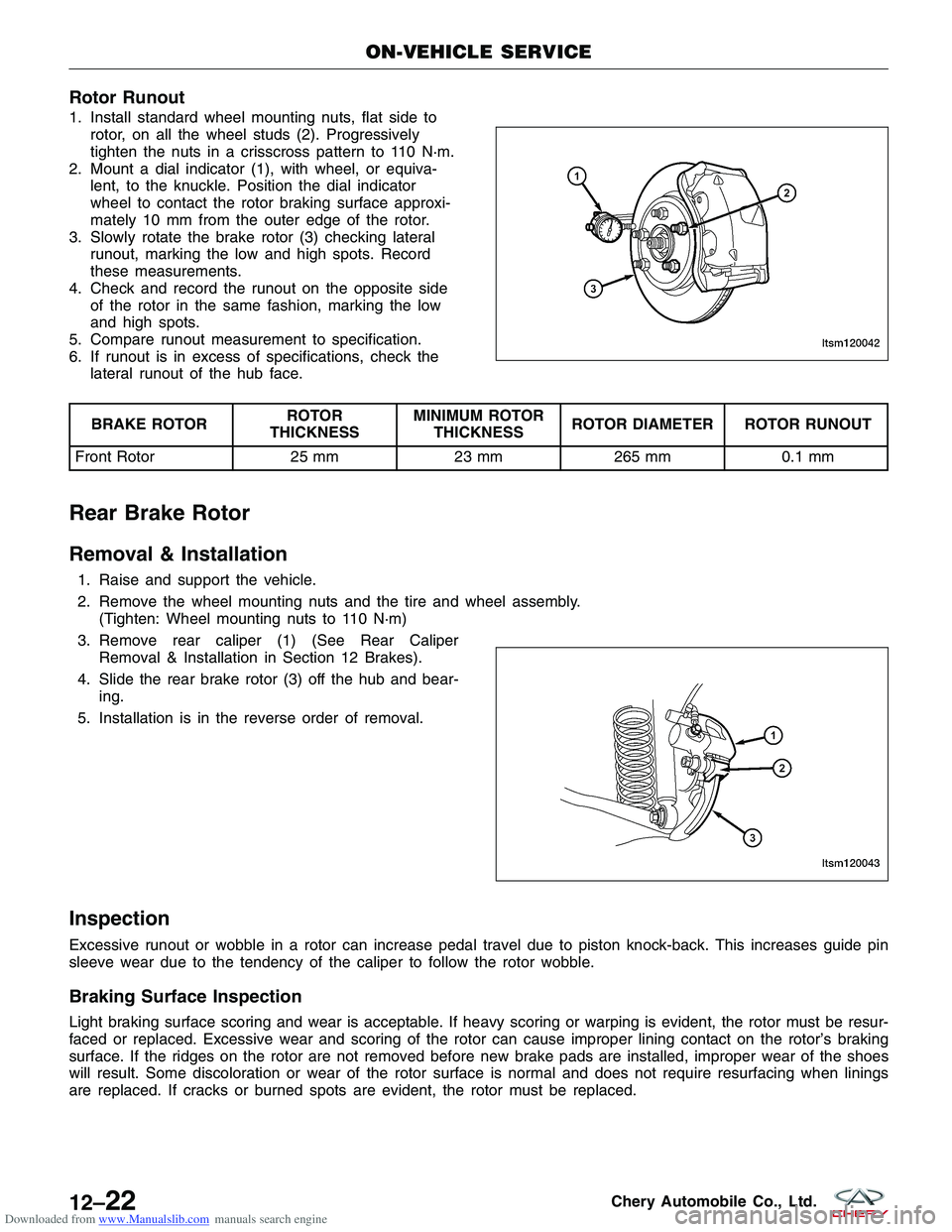
1. Install standard wheel mounting nuts, flat side torotor, on all the wheel studs (2). Progressively
tighten the nuts in a crisscross pattern to 110 N·m.
2. Mount a dial indicator (1), with wheel, or equiva- lent, to the knuckle. Position the dial indicator
wheel to contact the rotor braking surface approxi-
mately 10 mm from the outer edge of the rotor.
3. Slowly rotate the brake rotor (3) checking lateral runout, marking the low and high spots. Record
these measurements.
4. Check and record the runout on the opposite side of the rotor in the same fashion, marking the low
and high spots.
5. Compare runout measurement to specification.
6. If runout is in excess of specifications, check the lateral runout of the hub face.
BRAKE ROTOR ROTOR
THICKNESS MINIMUM ROTOR
THICKNESS ROTOR DIAMETER ROTOR RUNOUT
Front Rotor 25 mm23 mm265 mm 0.1 mm
Rear Brake Rotor
Removal & Installation
1. Raise and support the vehicle.
2. Remove the wheel mounting nuts and the tire and wheel assembly.
(Tighten: Wheel mounting nuts to 110 N·m)
3. Remove rear caliper (1) (See Rear Caliper Removal & Installation in Section 12 Brakes).
4. Slide the rear brake rotor (3) off the hub and bear- ing.
5. Installation is in the reverse order of removal.
Inspection
Excessive runout or wobble in a rotor can increase pedal travel due to piston knock-back. This increases guide pin
sleeve wear due to the tendency of the caliper to follow the rotor wobble.
Braking Surface Inspection
Light braking surface scoring and wear is acceptable. If heavy scoring or warping is evident, the rotor must be resur-
faced or replaced. Excessive wear and scoring of the rotor can cause improper lining contact on the rotor’s braking
surface. If the ridges on the rotor are not removed before new brake pads are installed, improper wear of the shoes
will result. Some discoloration or wear of the rotor surface is normal and does not require resurfacing when linings
are replaced. If cracks or burned spots are evident, the rotor must be replaced.
ON-VEHICLE SERVICE
LTSM120042
LTSM120043
12–22Chery Automobile Co., Ltd.
Page 1495 of 1903
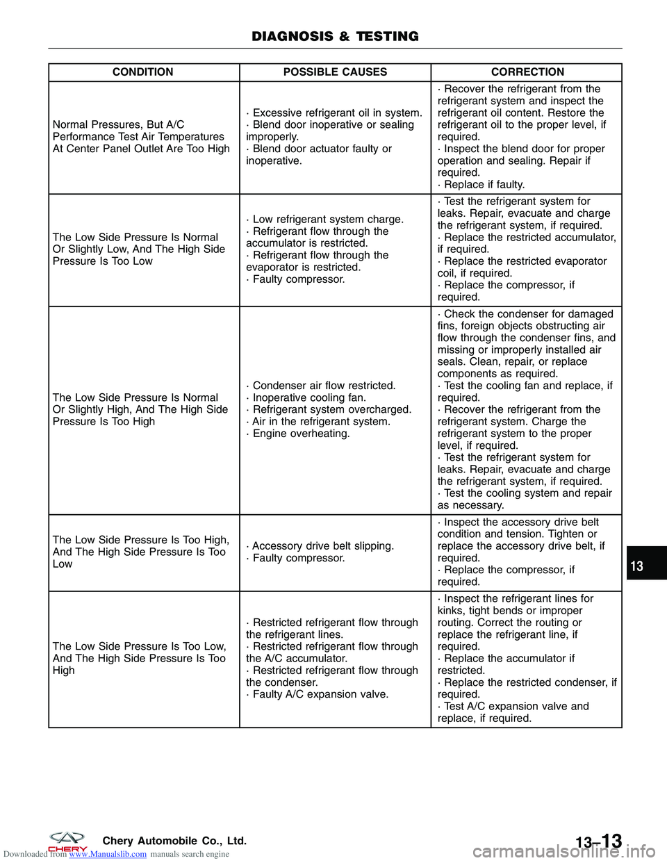
Downloaded from www.Manualslib.com manuals search engine CONDITIONPOSSIBLE CAUSES CORRECTION
Normal Pressures, But A/C
Performance Test Air Temperatures
At Center Panel Outlet Are Too High · Excessive refrigerant oil in system.
· Blend door inoperative or sealing
improperly.
· Blend door actuator faulty or
inoperative.· Recover the refrigerant from the
refrigerant system and inspect the
refrigerant oil content. Restore the
refrigerant oil to the proper level, if
required.
· Inspect the blend door for proper
operation and sealing. Repair if
required.
· Replace if faulty.
The Low Side Pressure Is Normal
Or Slightly Low, And The High Side
Pressure Is Too Low · Low refrigerant system charge.
· Refrigerant flow through the
accumulator is restricted.
· Refrigerant flow through the
evaporator is restricted.
· Faulty compressor.· Test the refrigerant system for
leaks. Repair, evacuate and charge
the refrigerant system, if required.
· Replace the restricted accumulator,
if required.
· Replace the restricted evaporator
coil, if required.
· Replace the compressor, if
required.
The Low Side Pressure Is Normal
Or Slightly High, And The High Side
Pressure Is Too High · Condenser air flow restricted.
· Inoperative cooling fan.
· Refrigerant system overcharged.
· Air in the refrigerant system.
· Engine overheating.· Check the condenser for damaged
fins, foreign objects obstructing air
flow through the condenser fins, and
missing or improperly installed air
seals. Clean, repair, or replace
components as required.
· Test the cooling fan and replace, if
required.
· Recover the refrigerant from the
refrigerant system. Charge the
refrigerant system to the proper
level, if required.
· Test the refrigerant system for
leaks. Repair, evacuate and charge
the refrigerant system, if required.
· Test the cooling system and repair
as necessary.
The Low Side Pressure Is Too High,
And The High Side Pressure Is Too
Low · Accessory drive belt slipping.
· Faulty compressor.· Inspect the accessory drive belt
condition and tension. Tighten or
replace the accessory drive belt, if
required.
· Replace the compressor, if
required.
The Low Side Pressure Is Too Low,
And The High Side Pressure Is Too
High · Restricted refrigerant flow through
the refrigerant lines.
· Restricted refrigerant flow through
the A/C accumulator.
· Restricted refrigerant flow through
the condenser.
· Faulty A/C expansion valve.· Inspect the refrigerant lines for
kinks, tight bends or improper
routing. Correct the routing or
replace the refrigerant line, if
required.
· Replace the accumulator if
restricted.
· Replace the restricted condenser, if
required.
· Test A/C expansion valve and
replace, if required.
DIAGNOSIS & TESTING
13
13–13Chery Automobile Co., Ltd.
Page 1496 of 1903
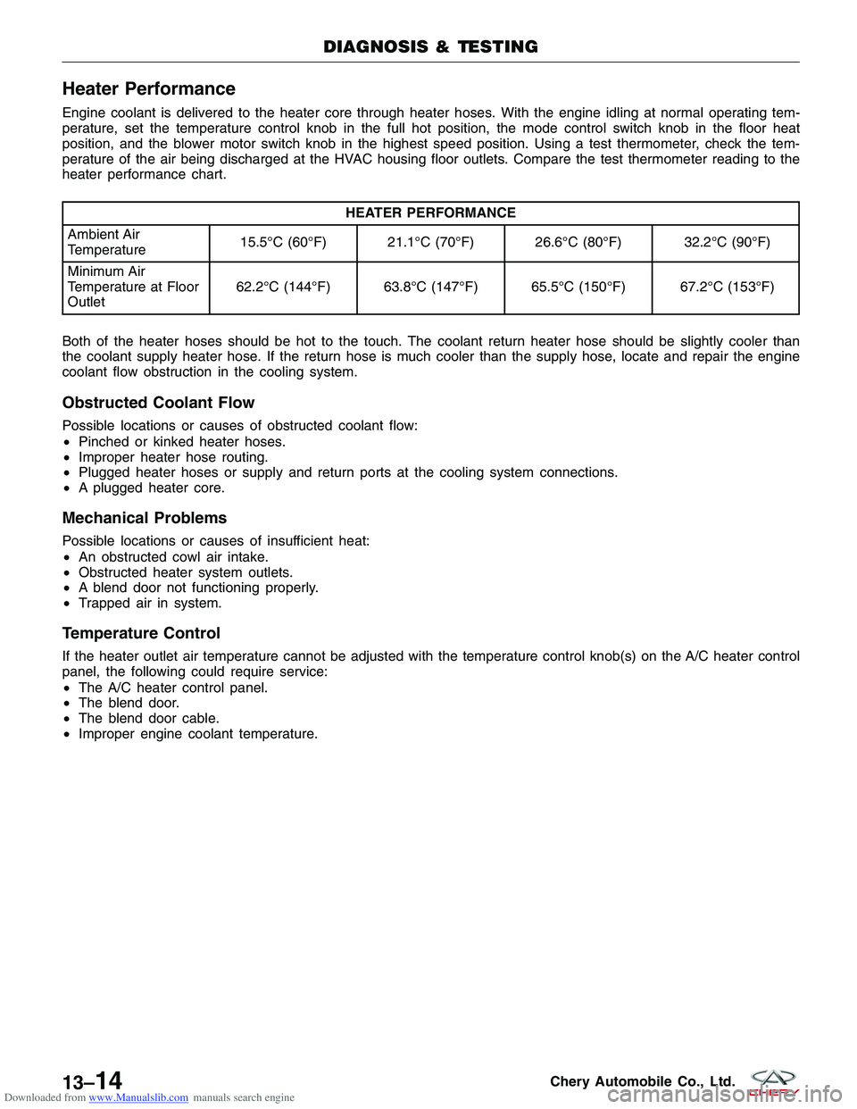
Downloaded from www.Manualslib.com manuals search engine Heater Performance
Engine coolant is delivered to the heater core through heater hoses. With the engine idling at normal operating tem-
perature, set the temperature control knob in the full hot position, the mode control switch knob in the floor heat
position, and the blower motor switch knob in the highest speed position. Using a test thermometer, check the tem-
perature of the air being discharged at the HVAC housing floor outlets. Compare the test thermometer reading to the
heater performance chart.
HEATER PERFORMANCE
Ambient Air
Temperature 15.5°C (60°F) 21.1°C (70°F) 26.6°C (80°F) 32.2°C (90°F)
Minimum Air
Temperature at Floor
Outlet 62.2°C (144°F) 63.8°C (147°F) 65.5°C (150°F) 67.2°C (153°F)
Both of the heater hoses should be hot to the touch. The coolant return heater hose should be slightly cooler than
the coolant supply heater hose. If the return hose is much cooler than the supply hose, locate and repair the engine
coolant flow obstruction in the cooling system.
Obstructed Coolant Flow
Possible locations or causes of obstructed coolant flow:
• Pinched or kinked heater hoses.
• Improper heater hose routing.
• Plugged heater hoses or supply and return ports at the cooling system connections.
• A plugged heater core.
Mechanical Problems
Possible locations or causes of insufficient heat:
•An obstructed cowl air intake.
• Obstructed heater system outlets.
• A blend door not functioning properly.
• Trapped air in system.
Temperature Control
If the heater outlet air temperature cannot be adjusted with the temperature control knob(s) on the A/C heater control
panel, the following could require service:
•The A/C heater control panel.
• The blend door.
• The blend door cable.
• Improper engine coolant temperature.
DIAGNOSIS & TESTING
13–14Chery Automobile Co., Ltd.
Page 1666 of 1903
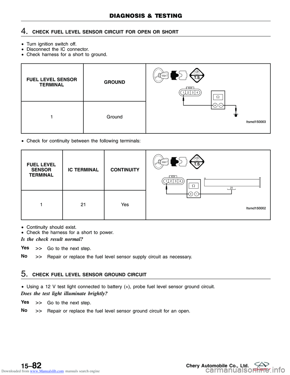
Downloaded from www.Manualslib.com manuals search engine 4.CHECK FUEL LEVEL SENSOR CIRCUIT FOR OPEN OR SHORT
• Turn ignition switch off.
• Disconnect the IC connector.
• Check harness for a short to ground.
FUEL LEVEL SENSOR
TERMINAL GROUND
1
Ground
• Check for continuity between the following terminals:
FUEL LEVEL
SENSOR
TERMINAL IC TERMINAL CONTINUITY
12
1Yes
• Continuity should exist.
• Check the harness for a short to power.
Is the check result normal?
Ye s>>Go to the next step.
No
>>Repair or replace the fuel level sensor supply circuit as necessary.
5.CHECK FUEL LEVEL SENSOR GROUND CIRCUIT
• Using a 12 V test light connected to battery (+), probe fuel level sensor ground circuit.
Does the test light illuminate brightly?
Ye s>>Go to the next step.
No
>>Repair or replace the fuel level sensor ground circuit for an open.
DIAGNOSIS & TESTING
15–82Chery Automobile Co., Ltd.
Page 1706 of 1903

Downloaded from www.Manualslib.com manuals search engine On Board Diagnostic Logic
•Self-diagnosis detection logic.
DTC NO. DTC DEFINITION DTC DETECTION
CONDITION DTC SET
CONDITION POSSIBLE CAUSE
B3042 W-line short circuit
to ground
Ignition switch: ON The Immobilizer
control module
detects a short
ground condition on
the W-Line for at
least 3 seconds.
•
Harness or
connectors
• Immobilizer control
module
• ECM
B3043 W-Line short circuit
to battery The Immobilizer
control module
detects a short
battery condition on
the W-Line for at
least 3 seconds.•
Harness or
connectors
• Immobilizer control
module
• ECM
DTC Confirmation Procedure:
Before performing the following procedure, confirm that battery voltage is more than 12 V.
• Turn ignition switch off.
• Connect the X-431 scan tool to the Data Link Connector (DLC) - use the most current software available.
• Turn ignition switch on, with the scan tool, view and erase stored DTCs in the Immobilizer control module.
• Try to start the engine.
• Turn ignition switch off, and wait a few seconds, then turn the ignition switch on.
• With the scan tool, view active DTCs in the Immobilizer control module.
• If the DTC is detected, the condition is current. Go to Diagnostic Procedure - Step 1.
• If the DTC is not detected, the DTC condition is intermittent (See Diagnostic Help and Intermittent DTC Trou-
bleshooting in Section 15 Body & Accessories for more information).
NOTE :
While performing electrical diagnosis & testing, always refer to the electrical schematics for specific circuit
and component information.
Diagnostic Procedure
1.CHECK GROUND CONNECTION
• Turn ignition switch off.
• Loosen and retighten ground screws on the body (See Ground Inspection in Section 15 Body & Accessories).
• Inspect ground connection C-204 mounting position (See Vehicle Wiring Harness Layout - Main Harness in
Section 16 Wiring).
Is the ground connection OK?
Ye s>>Go to the next step.
No
>>Repair or replace ground connection.
2.CHECK IMMOBILIZER CONTROL MODULE DTC
• With the scan tool, view DTCs in the Immobilizer control module. Refer to DTC confirmation procedure.
Is the warning light flashing and DTC B3042 or B3043 present?
Ye s>>Go to the next step.
No
>>The conditions that caused this code to set are not present at this time (See Diagnostic Help in Sec-
tion 15 Body & Accessories).
DIAGNOSIS & TESTING
15–122Chery Automobile Co., Ltd.
Page 1774 of 1903
Downloaded from www.Manualslib.com manuals search engine Headlamp Adjustment Procedure
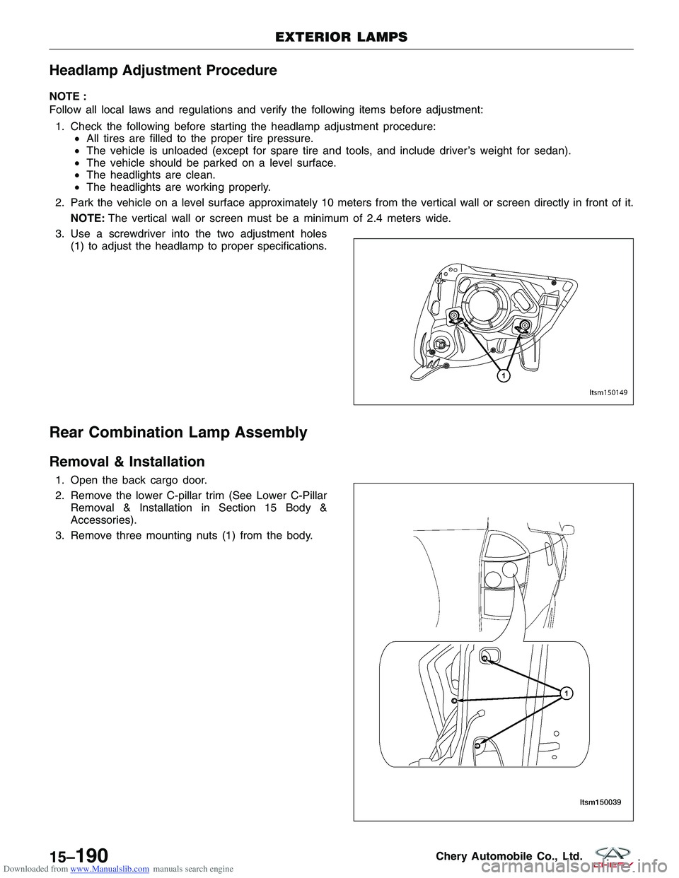
NOTE :
Follow all local laws and regulations and verify the following items before adjustment:1. Check the following before starting the headlamp adjustment procedure: •All tires are filled to the proper tire pressure.
• The vehicle is unloaded (except for spare tire and tools, and include driver’s weight for sedan).
• The vehicle should be parked on a level surface.
• The headlights are clean.
• The headlights are working properly.
2. Park the vehicle on a level surface approximately 10 meters from the vertical wall or screen directly in front of it. NOTE: The vertical wall or screen must be a minimum of 2.4 meters wide.
3. Use a screwdriver into the two adjustment holes (1) to adjust the headlamp to proper specifications.
Rear Combination Lamp Assembly
Removal & Installation
1. Open the back cargo door.
2. Remove the lower C-pillar trim (See Lower C-PillarRemoval & Installation in Section 15 Body &
Accessories).
3. Remove three mounting nuts (1) from the body.
EXTERIOR LAMPS
LTSM150149
LTSM150039
15–190Chery Automobile Co., Ltd.
Page 1805 of 1903
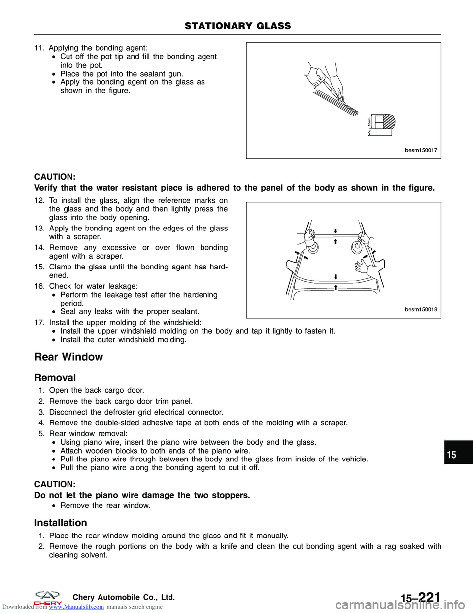
Downloaded from www.Manualslib.com manuals search engine 11. Applying the bonding agent:•Cut off the pot tip and fill the bonding agent
into the pot.
• Place the pot into the sealant gun.
• Apply the bonding agent on the glass as
shown in the figure.
CAUTION:
Verify that the water resistant piece is adhered to the panel of the body as shown in the figure.
12. To install the glass, align the reference marks on
the glass and the body and then lightly press the
glass into the body opening.
13. Apply the bonding agent on the edges of the glass with a scraper.
14. Remove any excessive or over flown bonding agent with a scraper.
15. Clamp the glass until the bonding agent has hard- ened.
16. Check for water leakage: •Perform the leakage test after the hardening
period.
• Seal any leaks with the proper sealant.
17. Install the upper molding of the windshield: •Install the upper windshield molding on the body and tap it lightly to fasten it.
• Install the outer windshield molding.
Rear Window
Removal
1. Open the back cargo door.
2. Remove the back cargo door trim panel.
3. Disconnect the defroster grid electrical connector.
4. Remove the double-sided adhesive tape at both ends of the molding with a scraper.
5. Rear window removal:
•Using piano wire, insert the piano wire between the body and the glass.
• Attach wooden blocks to both ends of the piano wire.
• Pull the piano wire through between the body and the glass from inside of the vehicle.
• Pull the piano wire along the bonding agent to cut it off.
CAUTION:
Do not let the piano wire damage the two stoppers.
•Remove the rear window.
Installation
1. Place the rear window molding around the glass and fit it manually.
2. Remove the rough portions on the body with a knife and clean the cut bonding agent with a rag soaked with
cleaning solvent.
STATIONARY GLASS
BESM150017
BESM150018
15
15–221Chery Automobile Co., Ltd.
Page 1807 of 1903
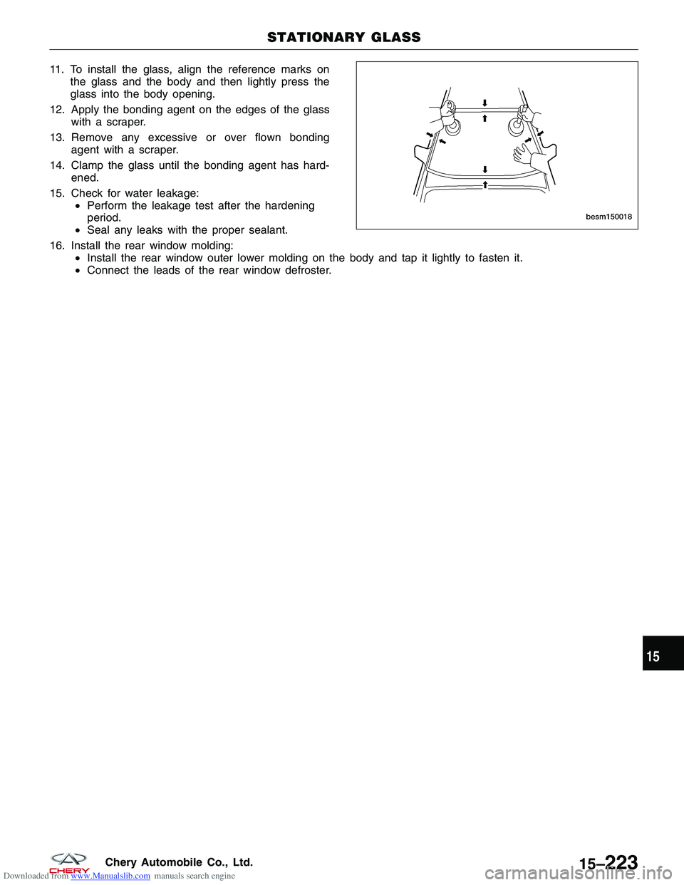
Downloaded from www.Manualslib.com manuals search engine 11. To install the glass, align the reference marks onthe glass and the body and then lightly press the
glass into the body opening.
12. Apply the bonding agent on the edges of the glass with a scraper.
13. Remove any excessive or over flown bonding agent with a scraper.
14. Clamp the glass until the bonding agent has hard- ened.
15. Check for water leakage: •Perform the leakage test after the hardening
period.
• Seal any leaks with the proper sealant.
16. Install the rear window molding: •Install the rear window outer lower molding on the body and tap it lightly to fasten it.
• Connect the leads of the rear window defroster.
STATIONARY GLASS
BESM150018
15
15–223Chery Automobile Co., Ltd.