2009 CHERY TIGGO air condition
[x] Cancel search: air conditionPage 173 of 1903
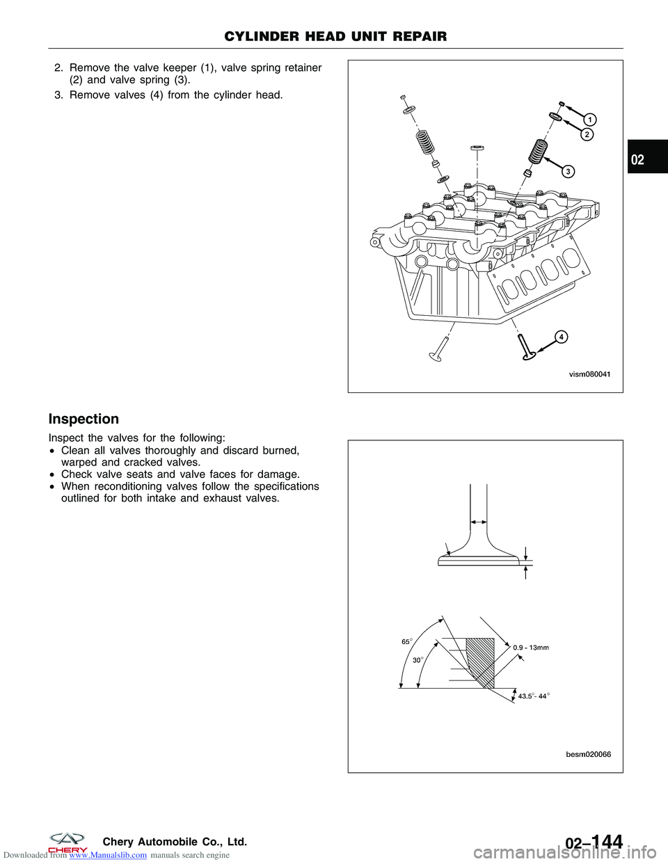
Downloaded from www.Manualslib.com manuals search engine 2. Remove the valve keeper (1), valve spring retainer(2) and valve spring (3).
3. Remove valves (4) from the cylinder head.
Inspection
Inspect the valves for the following:
• Clean all valves thoroughly and discard burned,
warped and cracked valves.
• Check valve seats and valve faces for damage.
• When reconditioning valves follow the specifications
outlined for both intake and exhaust valves.
CYLINDER HEAD UNIT REPAIR
VISM080041
BESM020066
02
02–144Chery Automobile Co., Ltd.
Page 176 of 1903

Downloaded from www.Manualslib.com manuals search engine 2. Remove the valve keeper (1), valve spring retainer(2).
3. Remove the valve springs (3) from the cylinder head.
Inspection
Inspect the valve springs for the following:
•Whenever valves have been removed for inspec-
tion, reconditioning or replacement, valve springs
should be tested for correct load.
• Discard the springs that do not meet specifications.
• The following specifications apply to both intake
and exhaust valve springs.
VALVE SPRING LENGTH/HEIGHT
Spring Free Length 47.7 mm
Spring Height At 620 Newtons Of Pressure 32.0 mm
If it is not within specifications, replace the valve spring.
CYLINDER HEAD UNIT REPAIR
VISM080040
BESM020072
02–147Chery Automobile Co., Ltd.
Page 192 of 1903

Downloaded from www.Manualslib.com manuals search engine DIAGNOSIS & TESTING
Engine Performance Diagnostics
CONDITIONPOSSIBLE CAUSES CORRECTION
Engine Does Not Start 1. Weak battery.
2. Corroded or loose battery
connections.
3. Faulty starter.
4. Faulty coil(s) or control unit.
5. Incorrect spark plug gap.
6. Contamination in fuel system.
7. Faulty fuel pump.
8. Incorrect timing.1. Test battery. Charge or replace if
necessary.
2. Clean and tighten battery
connections. Apply a coat of light
mineral grease to terminals.
3. Test starting system. Check for
codes. (Refer to Appropriate
Diagnostic Information)
4. Test and replace as needed.
(Refer to Appropriate Diagnostic
Information)
5. Set gap.
6. Clean system and replace fuel
filter.
7. Test fuel pump and replace as
needed. (Refer to Appropriate
Diagnostic Information)
8. Check for a skipped timing belt.
Engine Stalls Or Idles Rough 1. Idle speed too low.
2. Incorrect fuel mixture.
3. Intake manifold leakage.
4. Faulty ignition coil(s).1. Test minimum air flow. (Refer to
Appropriate Diagnostic Information)
2. (Refer to Appropriate Diagnostic
Information)
3. Inspect intake manifold, manifold
gasket, and vacuum hoses.
4. Test and replace if necessary.
(Refer to Appropriate Diagnostic
Information)
Engine Loss Of Power 1. Dirty or incorrectly gapped spark
plugs.
2. Contamination in fuel system.
3. Faulty fuel pump.
4. Incorrect valve timing.
5. Leaking cylinder head gasket.
6. Low compression.
7. Burned, warped, excessive
clearance, or pitted valves.
8. Plugged or restricted exhaust
system.
9. Faulty ignition coil(s).
10. Burned spark plugs.1. Clean spark plugs and set gap.
2. Clean system and replace fuel
filter.
3. Test and replace if necessary.
(Refer to Appropriate Diagnostic
Information)
4. Correct valve timing.
5. Replace cylinder head gasket.
6. Test compression of each
cylinder.
7. Replace valves.
8. Perform exhaust restriction test.
Install new parts.
9. Test and replace if necessary.
(Refer to Appropriate Diagnostic
Information)
10. Replace spark plugs.
DIAGNOSIS & TESTING
02
02–163Chery Automobile Co., Ltd.
Page 193 of 1903

Downloaded from www.Manualslib.com manuals search engine CONDITIONPOSSIBLE CAUSES CORRECTION
Engine Miss On Acceleration 1. Dirty or incorrectly gapped spark
plugs.
2. Contamination in fuel system.
7. Burned, warped, excessive
clearance, or pitted valves.
4. Faulty ignition coil(s).1. Clean spark plugs and set gap.
2. Clean fuel system and replace
fuel filter.
3. Replace valves.
4. Test and replace if necessary.
(Refer to Appropriate Diagnostic
Information)
Engine Miss At High Speed 1. Dirty or incorrect spark plug gap.
2. Faulty ignition coil(s).
3. Dirty fuel injector(s).
4. Contamination in fuel system.1. Clean spark plugs and set gap.
2. Test and replace if necessary.
(Refer to Appropriate Diagnostic
Information)
3. Test and replace if necessary.
(Refer to Appropriate Diagnostic
Information)
4. Clean system and replace fuel
filter.
Engine Mechanical Diagnostics
CONDITION
POSSIBLE CAUSES CORRECTION
Valve Train Noise 1. High or low oil level in crankcase.
2. Thin or diluted oil.
3. Thick oil.
4. Low oil pressure.
5. Worn cam lobe.
6. Worn valve guides.
7. Excessive runout of valve seats
on valve faces.1. Check and correct engine oil
level.
2. Change oil to correct viscosity.
3. Change engine oil and filter.
4. Check and correct engine oil
level.
5. Install new camshaft.
6. Replace cylinder head.
7. Grind valve seats and replace
valves.
Connecting Rod Noise 1. Insufficient oil supply.
2. Low oil pressure.
3. Thin or diluted oil.
4. Excessive bearing clearance.
5. Connecting rod journal out-of-
round.
6. Connecting rod out-of-round.
7. Misaligned connecting rods.
8. Connecting rod nuts loose.1. Check engine oil level.
2. Check engine oil level. Inspect oil
pump relief valve and spring.
3. Change oil to correct viscosity.
4. Measure bearings for correct
clearance. Repair if necessary.
5. Replace crankshaft or grind
surface.
6. Replace connecting rod.
7. Replace bent connecting rods.
8. Tighten the connecting rod nuts.
Main Bearing Noise 1. Insufficient oil supply.
2. Low oil pressure.
3. Thin or diluted oil.
4. Excessive bearing clearance.
5. Excessive end play.
6. Crankshaft journal out-of-round or
worn.
7. Loose flywheel or torque
converter.1. Check engine oil level.
2. Check engine oil level. Inspect oil
pump.
3. Change oil to correct viscosity.
4. Measure bearings for correct
clearance. Repair if necessary.
5. Check thrust bearing for wear on
flanges.
6. Replace crankshaft or grind
journals.
7. Tighten to correct torque.
DIAGNOSIS & TESTING
02–164Chery Automobile Co., Ltd.
Page 194 of 1903

Downloaded from www.Manualslib.com manuals search engine CONDITIONPOSSIBLE CAUSES CORRECTION
Oil Pressure Drop 1. Low oil level.
2. Faulty oil pressure sending unit.
3. Low oil pressure.
4. Clogged oil filter.
5. Thin or diluted oil.
6. Excessive bearing clearance.1. Check engine oil level.
2. Install new sending unit.
3. Check sending unit and main
bearing oil clearance.
4. Install new oil filter.
5. Change oil to correct viscosity.
6. Measure bearings for correct
clearance.
Oil Leaks 1. Misaligned or deteriorated
gaskets.
2. Loose fastener, broken or porous
metal part.
3. Misaligned or deteriorated cup or
threaded plug.1. Replace gasket.
2. Tighten, repair or replace the part.
3. Replace if necessary.
Oil Consumption Or Spark Plugs
Fouled 1. PCV system malfunction.
2. Worn, scuffed or broken rings.
3. Carbon in oil ring slots.
4. Rings fitted too tightly in grooves.
5. Worn valve guide(s).
6. Valve stem seal(s) worn or
damaged.1. Check system and repair if
necessary.
2. Hone cylinder bores. Install new
rings.
3. Install new rings.
4. Remove rings and check grooves.
If groove is not proper width, replace
piston.
5. Replace cylinder head.
6. Replace seal(s).
Cylinder Compression Pressure Test
•
The result of a cylinder compression pressure test
can be utilized to diagnose several engine malfunc-
tions.
• Ensure the battery is completely charged and the
engine starter motor is in good operating condition.
Otherwise the indicated compression pressures
may not be valid for diagnostic purposes.
Check engine oil level and add oil if neces-
sary.
Disconnect the spark plug wires.
Remove all spark plugs from engine (as spark plugs are being removed, check electrodes for
abnormal firing indicators fouled, hot, oily,
etc.).
Record cylinder number of each spark plug for future reference.
Disconnect fuel injector electrical connectors.
Be sure throttle blade is fully open during the compression check.
Insert compression pressure adaptor or the equivalent into each spark plug hole in cylinder head.
Crank engine until maximum pressure is reached on gauge. Record each cylinder pressure.
Compression should not be less than 880 kPa and not vary more than 25 percent from cylinder to cylinder.
If one or more cylinders have abnormally low compression pressures, repeat the compression test.
If the same cylinder or cylinders repeat an abnormally low reading on the second compression test, it could indicate the existence of a problem with the cylinder in question.
NOTE :
The recommended compression pressures are to be used only as a guide to diagnosing engine problems. An engine
should not be disassembled to determine the cause of low compression unless some malfunction is present.
DIAGNOSIS & TESTING
LTSM020191
02
02–165Chery Automobile Co., Ltd.
Page 212 of 1903

Downloaded from www.Manualslib.com manuals search engine Removal & Installation - Rear Mount
NOTE :
The following special tools are required to perform the
repair procedure:
•Engine Hoist
1. Disconnect the negative battery cable.
2. Support the engine with the engine hoist.
3. Remove the engine rear mount retaining bolts (2) and remove the engine rear mount bracket bolts
(1).
(Tighten: Engine rear mount bolts to 60 N·m)
4. Installation is in the reverse order of removal.
Engine Assembly
Removal & Installation
NOTE :
The following special tools are required to perform the repair procedure:
• Engine Hoist
NOTE :
The engine is removed with the transaxle as an assembly. 1. Relieve the fuel pressure (See Fuel Pressure Relief Procedure in Section 04 Fuel Delivery).
2. Disconnect the negative battery cable.
3. Remove the battery, battery hold downs, and battery tray (See Battery Removal & Installation in Section 05 Starting & Charging).
4. Remove the hood.
5. Discharge air conditioning system (See A/C System Evacuation and Recharge in Section 13 Heating & Air Con- ditioning).
6. Drain the cooling system (See Cooling System Draining and Filling in Section 06 Cooling).
WARNING!
Always allow the engine to cool before opening the cooling system. Do not loosen the coolant pressure relief
cap when the engine is operating or the cooling system is hot. The cooling system is under pressure; steam and
hot liquid can come out forcefully when the cap is loosened slightly. Failure to follow these instructions may
result in serious personal injury.
7. Remove the coolant fan & radiator assembly (See Coolant Fan & Radiator Assembly Removal & Installation in Section 06 Cooling).
8. Remove the starter motor wiring.
9. Remove the negative battery cable from the engine.
ON-VEHICLE SERVICE
LTSM020188
02
02–183Chery Automobile Co., Ltd.
Page 277 of 1903

Downloaded from www.Manualslib.com manuals search engine 1. Using the special tool MD-998772 (1), compressthe valve springs.
2. Remove the valve keeper, valve spring retainer and valve spring.
3. Remove valves from the cylinder head.
Valves
• Clean all valves thoroughly and discard burned,
warped and cracked valves.
• Check valve seats and valve faces for damage.
• When reconditioning valves follow the specifications
outlined for both intake and exhaust valves.
• Measure valve deflection.
VALVE DEFLECTION LIMIT (DIAL GAUGE READING)
Intake Valve 0.02 mm
Exhaust Valve 0.04 mm
CYLINDER HEAD UNIT REPAIR
LTSM020092
BESM020066
02–248Chery Automobile Co., Ltd.
Page 283 of 1903

Downloaded from www.Manualslib.com manuals search engine 1. Using the special tool MD-998772 (1), compressthe valve springs.
2. Remove the valve keeper, valve spring retainer.
3. Remove the valve springs from the cylinder head.
Inspection
NOTE :
Whenever valves have been removed for inspection, reconditioning or replacement, valve springs should be tested
for correct load.
• Check the valve spring length/height. Discard the springs that do not meet specifications.
• The following specifications apply to both intake
and exhaust valve springs.
VALVE SPRING LENGTH/HEIGHT
DESCRIPTION SPECIFICATION LIMIT
Spring Free Length 51.0 mm50.0 mm
CYLINDER HEAD UNIT REPAIR
LTSM020092
BESM020072
02–254Chery Automobile Co., Ltd.