Page 1622 of 1903

Downloaded from www.Manualslib.com manuals search engine BODY CONTROL MODULE - BCM
Description
The Body Control Module (BCM) is located behind the glove box. The BCM controls many electrical components and
systems for the vehicle electrical system. The BCM is the primary hub that controls functions such as internal and
external lighting, power windows and power door locks.
Operation
The Body Control Module (BCM) uses hard wired inputs from various sensors and switches. The sensors and
switches are located throughout the vehicle.
The following components are inputs to the BCM:
•Key switch
• Rear defroster switch
• Hazard lamp switch
• Power window switches
• Power door lock switches
• Seat belt switch
• Vehicle speed
• Door ajar switches
• Turn signal switch
The following components are outputs from the BCM:
• Key lamp
• Stop lamp relay
• Rear defroster grid
• Courtesy lamps
• Power window motor
• Power door lock motor
• Turn signal lamps
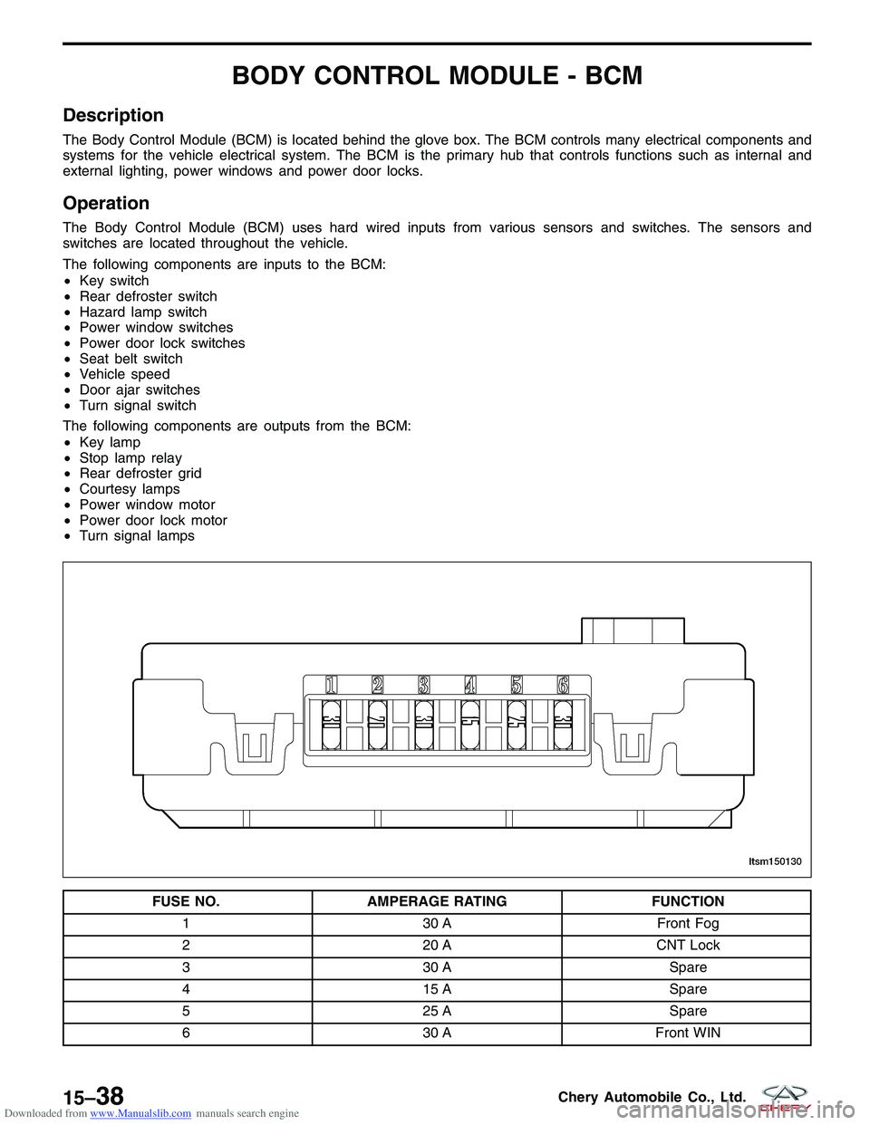
FUSE NO. AMPERAGE RATING FUNCTION
1 30 AFront Fog
2 20 ACNT Lock
3 30 A Spare
4 15 A Spare
5 25 A Spare
6 30 AFront WIN
LTSM150130
15–38Chery Automobile Co., Ltd.
Page 1698 of 1903
Downloaded from www.Manualslib.com manuals search engine Diagnostic Trouble Code (DTC) List
Immobilizer Control Module DTC List
DTCDTC DEFINITION
B1000 ECU Defect, Internal Errors
B3040 Communication Error On W-Line, ECM Doesn’t Answer On Challenge Or Response
Requests
B3042 W-Line Short Circuit To Ground
B3043 W-Line Short Circuit To Battery
B3045 DWA Line Short Circuit To Ground Or Open Circuit, DWA Line Malfunction
B3048 DWA Line Short Circuit To Battery
B3050 Relay Extern Line Short Circuit To Ground Or Open Circuit, Relay Extern Line
Malfunction
B3053 Relay Extern Line Short Circuit To Battery
B3055 No Transponder Modulation Or No Transponder
B3056 No Transponder Fix Code Programmed
B3057 No Security Code Programmed
B3060 Unprogrammed Transponder Fix Code Received
B3061 Disturbed Or No Challenge / Response Transponder Communication
B3077 Read-Only Transponder Detected
DIAGNOSIS & TESTING
15–11 4Chery Automobile Co., Ltd.
Page 1710 of 1903
Downloaded from www.Manualslib.com manuals search engine B3050 - Relay External Line Short Circuit To Ground Or Open Circuit, Relay External
Line Malfunction
B3053 - Relay External Line Short Circuit To Battery
DIAGNOSIS & TESTING
LTSMW150081T
15–126Chery Automobile Co., Ltd.
Page 1711 of 1903

Downloaded from www.Manualslib.com manuals search engine On Board Diagnostic Logic
•Self-diagnosis detection logic.
DTC NO. DTC DEFINITION DTC DETECTION
CONDITION DTC SET
CONDITION POSSIBLE CAUSE
B3050 Relay external line
short circuit to
ground or open
circuit, relay external line malfunction Ignition switch: ON The Immobilizer
control module
detects a short to
ground condition on
the W-Line for at
least 3 seconds. •
Harness or
connectors
• Immobilizer control
module
B3053 Relay external line
short circuit to battery Ignition switch: ON The Immobilizer
control module
detects a short to
battery condition on
the relay external
line. •
Harness or
connectors
• Immobilizer control
module
DTC Confirmation Procedure:
Before performing the following procedure, confirm that battery voltage is more than 12 V.
• Turn ignition switch off.
• Connect the X-431 scan tool to the Data Link Connector (DLC) - use the most current software available.
• Turn ignition switch on, with the scan tool, view and erase stored DTCs in the Immobilizer control module.
• Try to start the engine.
• Turn ignition switch off, and wait a few seconds, then turn ignition switch on.
• With the scan tool, view active DTCs in the Immobilizer control module.
• If the DTC is detected, the condition is current. Go to Diagnostic Procedure - Step 1.
• If the DTC is not detected, the DTC condition is intermittent (See Diagnostic Help and Intermittent DTC Trou-
bleshooting in Section 15 Body & Accessories for more information).
NOTE :
While performing electrical diagnosis & testing, always refer to the electrical schematics for specific circuit
and component information.
DIAGNOSIS & TESTING
15
15–127Chery Automobile Co., Ltd.
Page 1713 of 1903
Downloaded from www.Manualslib.com manuals search engine 4.CHECK IMMOBILIZER CONTROL MODULE POWER SUPPLY
• Turn ignition switch on.
• Check if voltage is present on the Immobilizer control module connector C-025, pin 4,1 and ground.
IMMOBILIZER CONTROL
MODULE TERMINAL GROUND
1
Ground
4
Is 12 V present?
Ye s>>Replace and program the Immobilizer control module. Refer to DTC B3077 Diagnostic Procedure.
No
>>For DTC B3050, go to the next step.
For DTC B3053, go to the step 6.
5.CHECK IMMOBILIZER CONTROL MODULE POWER SUPPLY CIRCUIT
• Turn ignition switch off.
• Disconnect the negative battery cable.
• Disconnect the body fuse and relay box electrical connector A.
• Check harness continuity between the following terminals:
• Continuity should exist.
BODY FUSE
AND RELAY BOX
TERMINAL IMMOBILIZER
CONTROLMODULE
TERMINAL CONTINUITY
A2
1Yes
DIAGNOSIS & TESTING
15
15–129Chery Automobile Co., Ltd.
Page 1714 of 1903

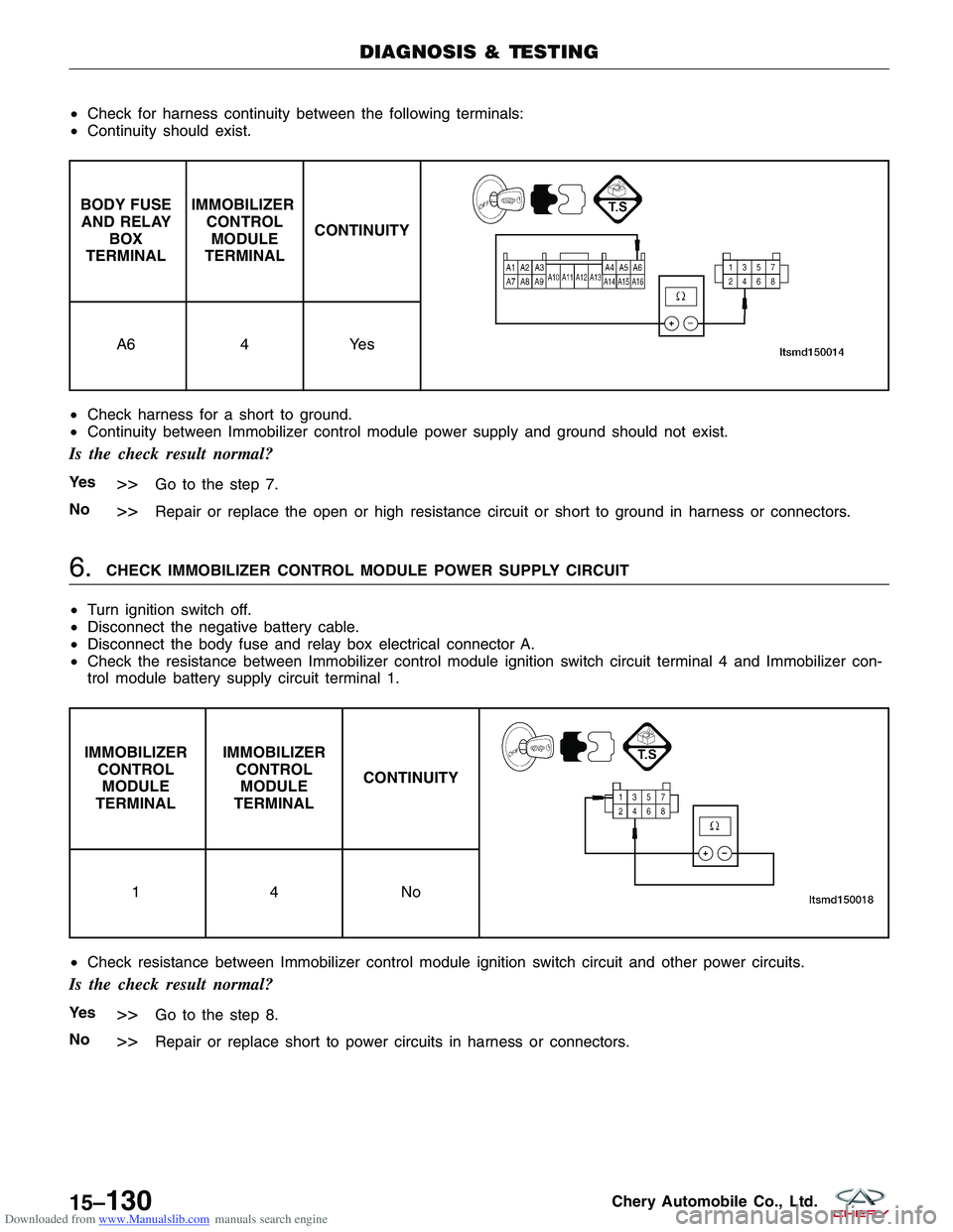
Downloaded from www.Manualslib.com manuals search engine •Check for harness continuity between the following terminals:
• Continuity should exist.
BODY FUSE
AND RELAY BOX
TERMINAL IMMOBILIZER
CONTROLMODULE
TERMINAL CONTINUITY
A6
4Yes
• Check harness for a short to ground.
• Continuity between Immobilizer control module power supply and ground should not exist.
Is the check result normal?
Ye s>>Go to the step 7.
No
>>Repair or replace the open or high resistance circuit or short to ground in harness or connectors.
6.CHECK IMMOBILIZER CONTROL MODULE POWER SUPPLY CIRCUIT
• Turn ignition switch off.
• Disconnect the negative battery cable.
• Disconnect the body fuse and relay box electrical connector A.
• Check the resistance between Immobilizer control module ignition switch circuit terminal 4 and Immobilizer con-
trol module battery supply circuit terminal 1.
IMMOBILIZER
CONTROLMODULE
TERMINAL IMMOBILIZER
CONTROLMODULE
TERMINAL CONTINUITY
14N
o
• Check resistance between Immobilizer control module ignition switch circuit and other power circuits.
Is the check result normal?
Ye s>>Go to the step 8.
No
>>Repair or replace short to power circuits in harness or connectors.
DIAGNOSIS & TESTING
15–130Chery Automobile Co., Ltd.
Page 1715 of 1903
Downloaded from www.Manualslib.com manuals search engine 7.DETECT MALFUNCTIONING PART
• Check the following:
� Body fuse and relay box
� Fuse F17 (10A), fuse F26 (10A)
� Harness between battery and body fuse and relay box
Is the check result normal?
Ye s>>Go to the next step.
No
>>Repair or replace damaged components.
8.REPLACE AND PROGRAM THE IMMOBILIZER CONTROL MODULE
• With the X-431 scan tool, view active DTCs in the Immobilizer control module.
• Refer to �DTC Confirmation Procedure�.
Is DTC B3050 or B3053 still present?
Ye s>>Replace and program Immobilizer control module.
No
>>The system is now operating properly.
Reassemble the vehicle and verify the customers complaint is repaired.
DIAGNOSIS & TESTING
15
15–131Chery Automobile Co., Ltd.
Page 1827 of 1903

Downloaded from www.Manualslib.com manuals search engine WIRING
16
CONTENTSpage
Wiring Information ................................................................... 16-1
Vehicle Power Distribution ............................................................ 16-12
Vehicle Ground Distribution ........................................................... 16-27
Vehicle Fuse Box Information ......................................................... 16-37
Vehicle Wiring Harness Layout ........................................................ 16-44
WIRING INFORMATION
GENERAL INFORMATION16-2
Description 16-2
Electrical Schematics 16-2
International Symbols 16-3
ELECTRICAL TROUBLESHOOTING16-5
Troubleshooting Wiring Problems 16-5
Testing For Voltage 16-5
Testing For Continuity 16-5
Testing For A Short To Ground 16-5
Intermittent and Poor Connections 16-5
ELECTRICAL TROUBLESHOOTING TOOLS
16-6
Jumper Wires 16-6 Voltmeter 16-6
Ohmmeter 16-7
ELECTRICAL REPAIR16-8
Wire Repair 16-8
Fuse Replacement 16-8
ELECTRICAL COMPONENTS16-9
Battery Cable 16-9
Sensors, Switches, and Relays 16-9
Connectors 16-10
16
16–1Chery Automobile Co., Ltd.