Page 1315 of 1903
Downloaded from www.Manualslib.com manuals search engine Operation
The strut assembly cushions the ride of the vehicle, controlling vibration, jounce and rebound of the suspension. The
coil spring controls ride quality and maintains proper ride height. The spring isolators isolate the coil spring at the top
and bottom from coming into metal-to-metal contact with the upper mounting seat and the strut. The strut dampens
jounce and rebound motions of the coil spring and suspension.
Diagnosis & Testing
Before removing the front strut, perform the following to test the front strut functionality:
•Adjust the tire pressure to all tires to proper specifications.
• Push and shake the front of the vehicle three or four times with identical force every time
• During the pushing and recoiling, the resistance and recoil times of the vehicle should be equal.
• If the strut (shock absorber) functions properly, the vehicle will recoil several times and then stop recoiling after
the pushing force is removed.
Removal & Installation
1. Raise and support the vehicle.
2. Remove the wheel mounting nuts and the wheel assembly.
(Tighten: Wheel mounting nuts to 110 N·m)
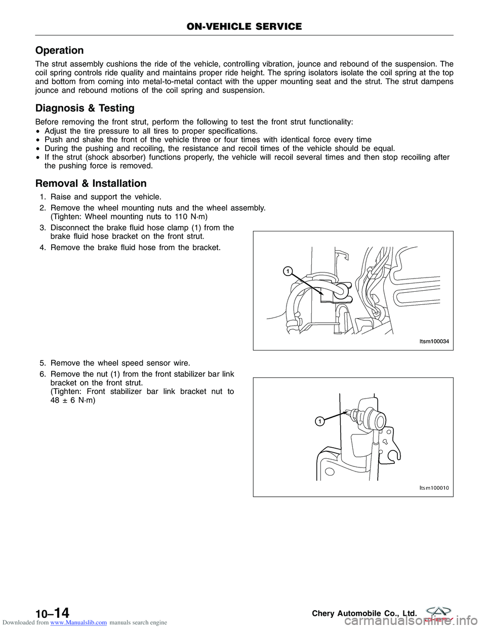
3. Disconnect the brake fluid hose clamp (1) from the brake fluid hose bracket on the front strut.
4. Remove the brake fluid hose from the bracket.
5. Remove the wheel speed sensor wire.
6. Remove the nut (1) from the front stabilizer bar link bracket on the front strut.
(Tighten: Front stabilizer bar link bracket nut to
48 ± 6 N·m)
ON-VEHICLE SERVICE
LTSM100034
LTSM100010
10–14Chery Automobile Co., Ltd.
Page 1328 of 1903
Downloaded from www.Manualslib.com manuals search engine WARNING!
Only frame contact or wheel lift hoisting equipment can be used on this vehicle. It cannot be hoisted using
equipment designed to lift a vehicle by the rear axle. If this type of hoisting equipment is used, damage to rear
suspension components will occur.
CAUTION:
If a rear suspension component becomes bent, damaged or fails, no attempt should be made to
straighten or repair it. Always replace it with a new component.
Operation
The rear suspension utilizes an independent multi-link arm design. This suspension system allows the wheels to
react to road imperfections independent of each other. This independent action offers improved isolation from the
effects of jounce and rebound.
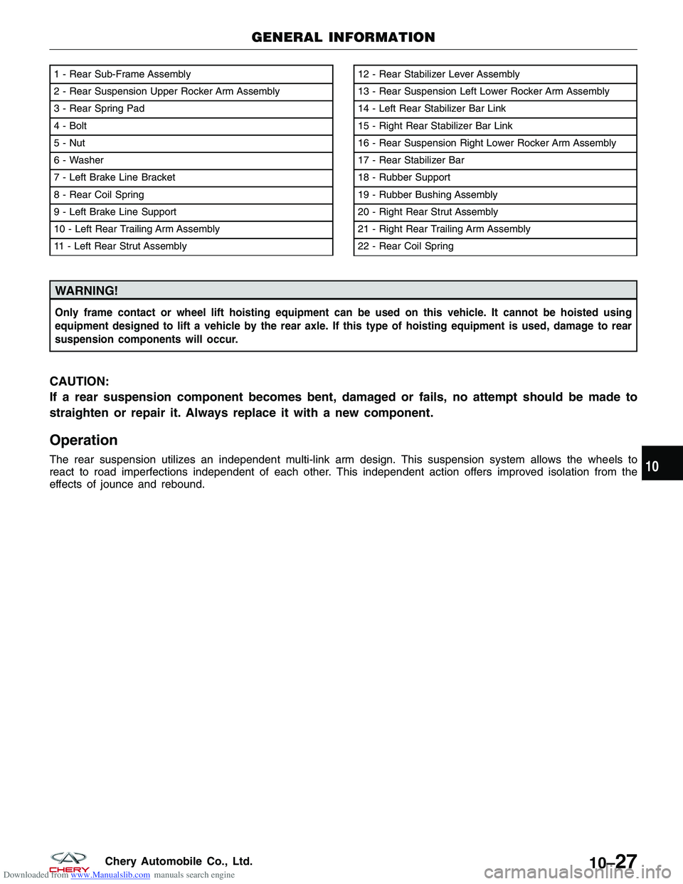
1 - Rear Sub-Frame Assembly
2 - Rear Suspension Upper Rocker Arm Assembly
3 - Rear Spring Pad
4 - Bolt
5 - Nut
6 - Washer
7 - Left Brake Line Bracket
8 - Rear Coil Spring
9 - Left Brake Line Support
10 - Left Rear Trailing Arm Assembly
11 - Left Rear Strut Assembly12 - Rear Stabilizer Lever Assembly
13 - Rear Suspension Left Lower Rocker Arm Assembly
14 - Left Rear Stabilizer Bar Link
15 - Right Rear Stabilizer Bar Link
16 - Rear Suspension Right Lower Rocker Arm Assembly
17 - Rear Stabilizer Bar
18 - Rubber Support
19 - Rubber Bushing Assembly
20 - Right Rear Strut Assembly
21 - Right Rear Trailing Arm Assembly
22 - Rear Coil Spring
GENERAL INFORMATION
LTSM100035
10
10–27Chery Automobile Co., Ltd.
Page 1337 of 1903
Downloaded from www.Manualslib.com manuals search engine 8. Remove the connecting bolt (1) that joins the reartrailing arm to the hand brake cable bracket.
(Tighten: Hand brake cable bracket bolt to
25 - 35 N·m)
9. Remove the bolt (1) that joins the rear trailing arm to the vehicle body.
10. Remove the brake fluid pipe clamp (2).
ON-VEHICLE SERVICE
LTSM100059
LTSM100054
10–36Chery Automobile Co., Ltd.
Page 1338 of 1903
Downloaded from www.Manualslib.com manuals search engine 11. Remove the brake fluid pipe clamp (1) and bracketbolts (2) on the trailing arm.
12. Remove the rear brake rotor (See Rear Brake Rotor Removal & Installation in Section 10 Brakes).
13. Remove the rear hub and bearing (See Rear Hub and Bearing Removal & Installation in Section 09 Driveline & Axle).
14. Remove the rear trailing arm.
15. Installation is in the reverse order of removal.
Installation Notes:
• After installation, each bolt must be tightened to the required tightening torque.
ON-VEHICLE SERVICE
LTSM100067
10
10–37Chery Automobile Co., Ltd.
Page 1349 of 1903
Downloaded from www.Manualslib.com manuals search engine GENERAL INFORMATION
Description
Tires are designed and engineered for each specific vehicle. They provide the best overall performance for normal
operation. The ride and handling characteristics match the vehicle’s requirements. With proper care they will give
excellent reliability, traction, skid resistance, and tread life.
Tire Identification
•Tire type, size, load index and speed rating are encoded in the letters and numbers imprinted on the side wall
of the tire.
Spare Tire
• A full size spare tire and wheel assembly is standard equipment on this vehicle. The original tire should be
repaired or replaced at the first opportunity, then reinstalled.
Operation
Driving habits have more effect on tire life than any other factor. Careful drivers will obtain, in most cases, much
greater mileage than severe use or careless drivers. A few of the driving habits which will shorten the life of any tire
are:
•Rapid acceleration
• Severe application of brakes
• High-speed driving
• Taking turns at excessive speeds
• Striking curbs and other obstacles
• Operating vehicle with over or under inflated tire pressures
Specifications
Torque Specifications
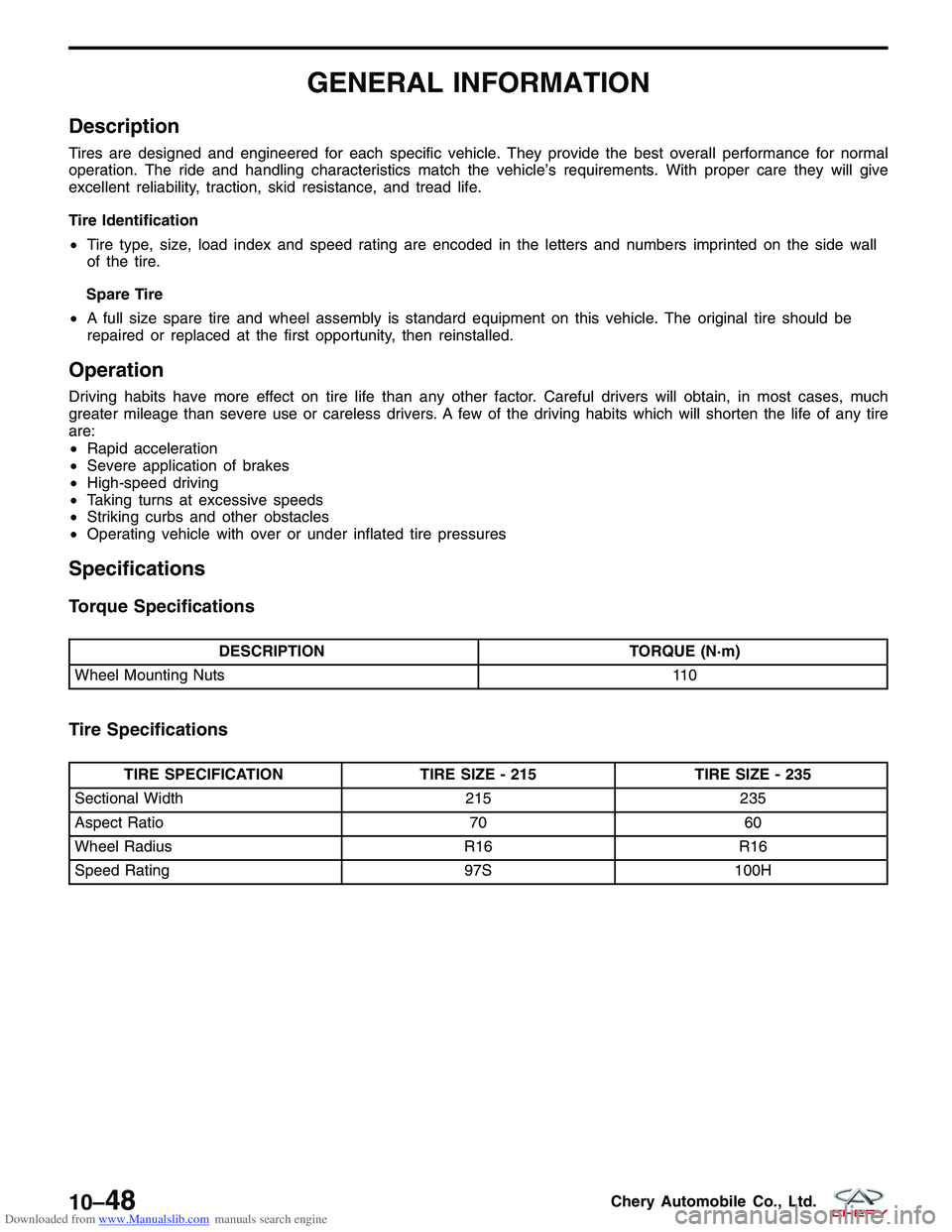
DESCRIPTION TORQUE (N·m)
Wheel Mounting Nuts 110
Tire Specifications
TIRE SPECIFICATIONTIRE SIZE - 215TIRE SIZE - 235
Sectional Width 215235
Aspect Ratio 7060
Wheel Radius R16R16
Speed Rating 97S100H
10–48Chery Automobile Co., Ltd.
Page 1366 of 1903
Downloaded from www.Manualslib.com manuals search engine DIAGNOSIS & TESTING
Vehicle Inspection
There is some noise in all power steering systems. One of the most common is a hissing sound. Hiss is a high
frequency noise similar to that of a water tap being closed slowly. The noise is present in all valves that have a high
velocity steering fluid passing through an orifice. There is no relationship between this noise and steering perfor-
mance. The hissing sound is commonly heard during the following operations:
•Evident at a standstill
• At park with the engine running
• When the steering wheel is at the end of its travel
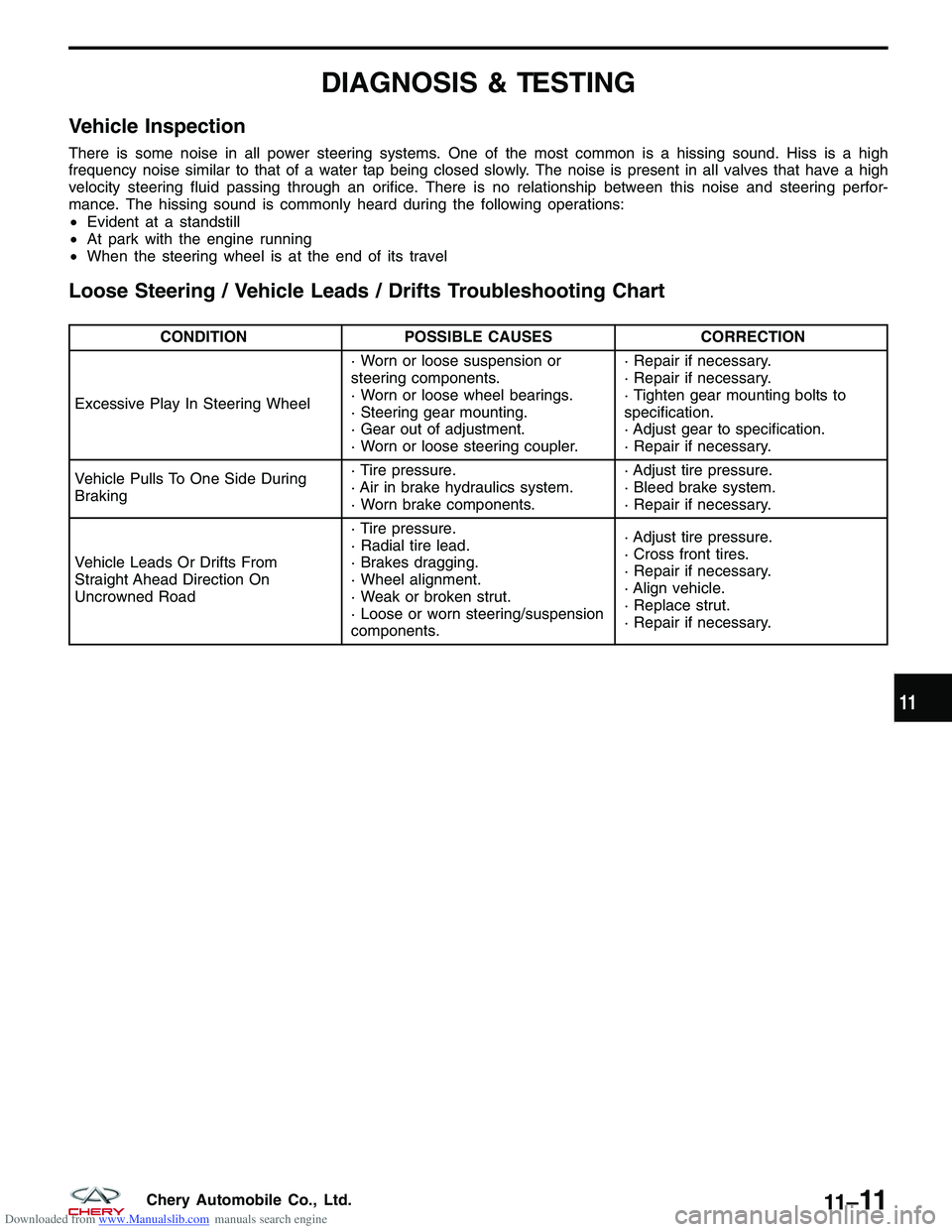
Loose Steering / Vehicle Leads / Drifts Troubleshooting Chart
CONDITION POSSIBLE CAUSES CORRECTION
Excessive Play In Steering Wheel · Worn or loose suspension or
steering components.
· Worn or loose wheel bearings.
· Steering gear mounting.
· Gear out of adjustment.
· Worn or loose steering coupler.· Repair if necessary.
· Repair if necessary.
· Tighten gear mounting bolts to
specification.
· Adjust gear to specification.
· Repair if necessary.
Vehicle Pulls To One Side During
Braking · Tire pressure.
· Air in brake hydraulics system.
· Worn brake components.· Adjust tire pressure.
· Bleed brake system.
· Repair if necessary.
Vehicle Leads Or Drifts From
Straight Ahead Direction On
Uncrowned Road · Tire pressure.
· Radial tire lead.
· Brakes dragging.
· Wheel alignment.
· Weak or broken strut.
· Loose or worn steering/suspension
components.· Adjust tire pressure.
· Cross front tires.
· Repair if necessary.
· Align vehicle.
· Replace strut.
· Repair if necessary.
11
11 –11Chery Automobile Co., Ltd.
Page 1396 of 1903
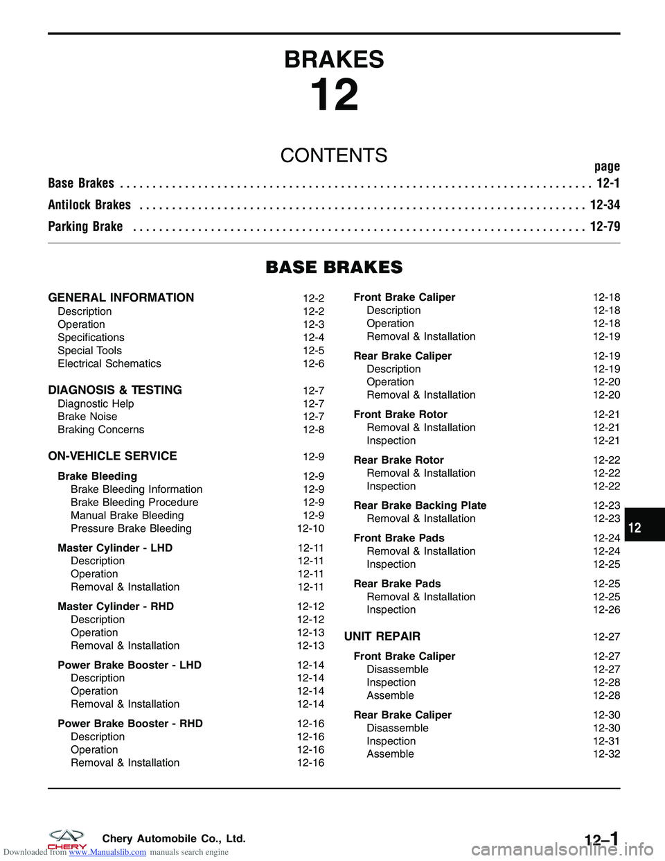
Downloaded from www.Manualslib.com manuals search engine BRAKES
12
CONTENTSpage
Base Brakes ........................................................................\
. 12-1
Antilock Brakes ..................................................................... 12-34
Parking Brake ...................................................................... 12-79
BASE BRAKES
GENERAL INFORMATION12-2
Description 12-2
Operation 12-3
Specifications 12-4
Special Tools 12-5
Electrical Schematics 12-6
DIAGNOSIS & TESTING12-7
Diagnostic Help 12-7
Brake Noise 12-7
Braking Concerns 12-8
ON-VEHICLE SERVICE12-9
Brake Bleeding 12-9
Brake Bleeding Information 12-9
Brake Bleeding Procedure 12-9
Manual Brake Bleeding 12-9
Pressure Brake Bleeding 12-10
Master Cylinder - LHD 12-11
Description 12-11
Operation 12-11
Removal & Installation 12-11
Master Cylinder - RHD 12-12
Description 12-12
Operation 12-13
Removal & Installation 12-13
Power Brake Booster - LHD 12-14
Description 12-14
Operation 12-14
Removal & Installation 12-14
Power Brake Booster - RHD 12-16
Description 12-16
Operation 12-16
Removal & Installation 12-16Front Brake Caliper
12-18
Description 12-18
Operation 12-18
Removal & Installation 12-19
Rear Brake Caliper 12-19
Description 12-19
Operation 12-20
Removal & Installation 12-20
Front Brake Rotor 12-21
Removal & Installation 12-21
Inspection 12-21
Rear Brake Rotor 12-22
Removal & Installation 12-22
Inspection 12-22
Rear Brake Backing Plate 12-23
Removal & Installation 12-23
Front Brake Pads 12-24
Removal & Installation 12-24
Inspection 12-25
Rear Brake Pads 12-25
Removal & Installation 12-25
Inspection 12-26
UNIT REPAIR12-27
Front Brake Caliper 12-27
Disassemble 12-27
Inspection 12-28
Assemble 12-28
Rear Brake Caliper 12-30
Disassemble 12-30
Inspection 12-31
Assemble 12-32
12
12–1Chery Automobile Co., Ltd.
Page 1397 of 1903
Downloaded from www.Manualslib.com manuals search engine GENERAL INFORMATION
Description
Base Brakes
The base brake system consists of the following components:
•Brake pedal
• Power brake booster
• Master cylinder
• Brake tubes and hoses
• Disc brakes (front)
• Disc brakes (rear)
• Parking brake
• Parking brake shoes (rear)
Front Disc Brake
The front disc brake assembly consists of the following major components:
•Caliper
• Caliper adapter bracket
• Brake pads
• Rotor
1 - Front Wheel Knuckle
2 - Knuckle Hub Bearing
3 - Front Wheel Hub Assembly
4 - Dust Shield5 - Front Brake Rotor
6 - Brake Caliper Assembly
7 - Disc Brake Caliper and Rotor Assembly
LTSM120001
12–2Chery Automobile Co., Ltd.