Page 1406 of 1903
Downloaded from www.Manualslib.com manuals search engine 6. Check the brake pedal travel. If pedal travel is excessive or has not been improved, some air may still betrapped in the system. Re-bleed the brakes as necessary.
7. Test drive the vehicle to verify the brakes are operating properly and pedal feel is correct.
Master Cylinder - LHD
Description
The master cylinder body is an anodized aluminum casting. It is located at the left side of the engine room. It has a
machined bore to accept the master cylinder pistons and also has threaded ports with seats for hydraulic brake tube
connections. The master cylinder has the brake fluid reservoir mounted on top of it and supplies brake fluid to the
master cylinder as required. On manual transaxle equipped vehicles, the brake fluid reservoir also feeds the clutch
hydraulic circuit. The reservoir is made of clear plastic and it houses the brake fluid level switch.
Operation
When the brake pedal is pressed, the master cylinder pistons apply brake pressure through the chassis brake tubes
to each brake assembly. The brake fluid reservoir supplies the brake hydraulic system with the necessary fluid to
operate properly.
Removal & Installation
CAUTION:
The vacuum in the power brake booster must be pumped down before removing the master cyl-
inder to avoid damaging the master cylinder and to prevent the booster from sucking in any con-
tamination. This can be done by pumping the brake pedal while the engine is not running until a
firm brake pedal is achieved.
1. Turn the ignition switch off.
2. Siphon out as much brake fluid as possible from the master cylinder.
3. With the engine off, pump the brake pedal 4-5 strokes until the pedal feel is firm.
4. Disconnect the negative battery cable.
5. Disconnect the brake fluid level switch electrical connector in the master cylinder brake fluid reservoir.
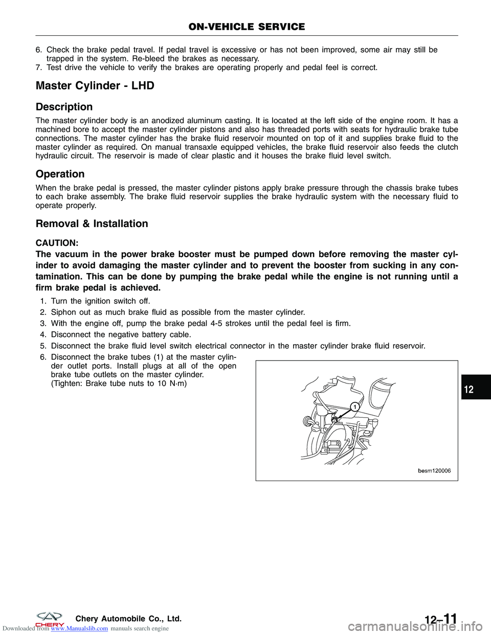
6. Disconnect the brake tubes (1) at the master cylin- der outlet ports. Install plugs at all of the open
brake tube outlets on the master cylinder.
(Tighten: Brake tube nuts to 10 N·m)
ON-VEHICLE SERVICE
BESM120006
12
12–11Chery Automobile Co., Ltd.
Page 1407 of 1903
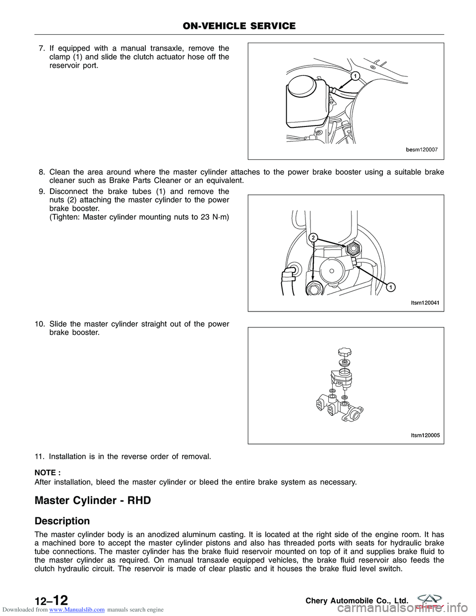
Downloaded from www.Manualslib.com manuals search engine 7. If equipped with a manual transaxle, remove theclamp (1) and slide the clutch actuator hose off the
reservoir port.
8. Clean the area around where the master cylinder attaches to the power brake booster using a suitable brake cleaner such as Brake Parts Cleaner or an equivalent.
9. Disconnect the brake tubes (1) and remove the nuts (2) attaching the master cylinder to the power
brake booster.
(Tighten: Master cylinder mounting nuts to 23 N·m)
10. Slide the master cylinder straight out of the power brake booster.
11. Installation is in the reverse order of removal.
NOTE :
After installation, bleed the master cylinder or bleed the entire brake system as necessary.
Master Cylinder - RHD
Description
The master cylinder body is an anodized aluminum casting. It is located at the right side of the engine room. It has
a machined bore to accept the master cylinder pistons and also has threaded ports with seats for hydraulic brake
tube connections. The master cylinder has the brake fluid reservoir mounted on top of it and supplies brake fluid to
the master cylinder as required. On manual transaxle equipped vehicles, the brake fluid reservoir also feeds the
clutch hydraulic circuit. The reservoir is made of clear plastic and it houses the brake fluid level switch.
ON-VEHICLE SERVICE
BESM120007
LTSM120041
LTSM120005
12–12Chery Automobile Co., Ltd.
Page 1408 of 1903
Downloaded from www.Manualslib.com manuals search engine Operation
When the brake pedal is pressed, the master cylinder pistons apply brake pressure through the chassis brake tubes
to each brake assembly. The brake fluid reservoir supplies the brake hydraulic system with the necessary fluid to
operate properly.
Removal & Installation
CAUTION:
The vacuum in the power brake booster must be pumped down before removing the master cyl-
inder to avoid damaging the master cylinder and to prevent the booster from sucking in any con-
tamination. This can be done by pumping the brake pedal while the engine is not running until a
firm brake pedal is achieved.
1. Turn the ignition switch off.
2. Siphon out as much brake fluid as possible from the master cylinder.
3. With the engine off, pump the brake pedal 4-5 strokes until the pedal feel is firm.
4. Disconnect the negative battery cable.
5. Disconnect the brake fluid level switch electrical connector in the master cylinder brake fluid reservoir.
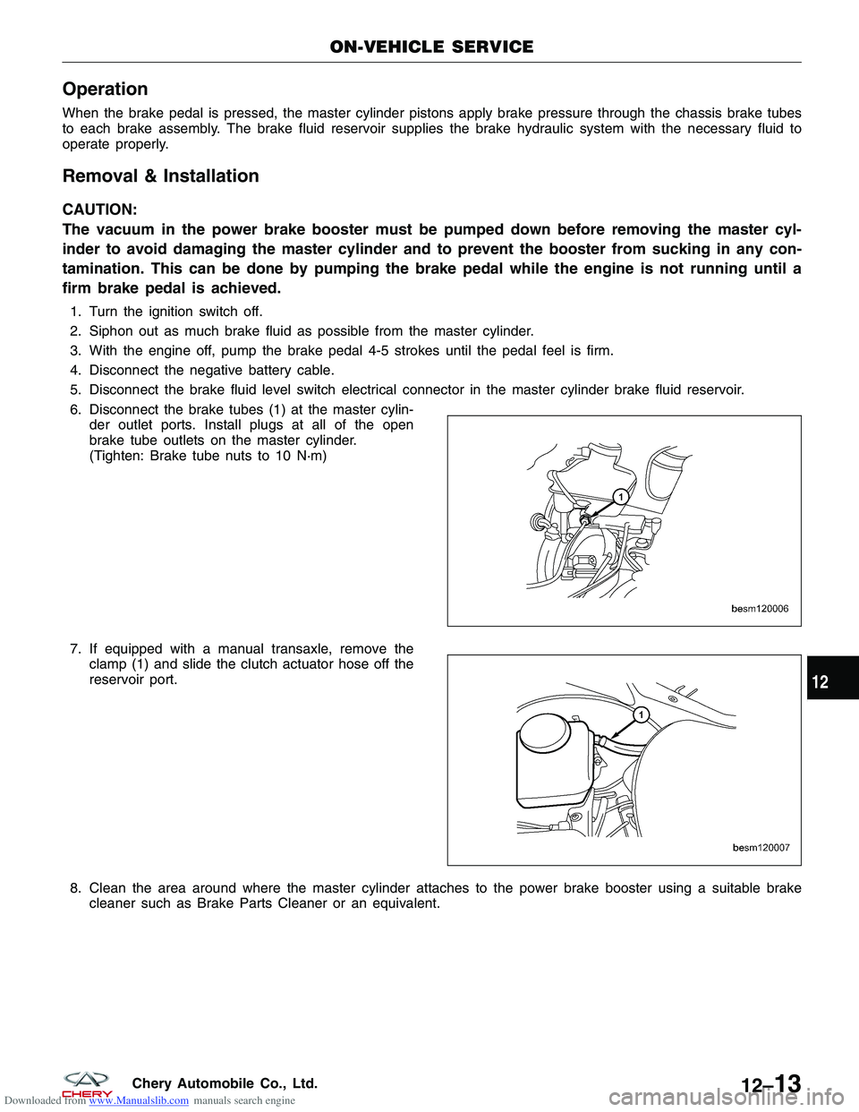
6. Disconnect the brake tubes (1) at the master cylin-der outlet ports. Install plugs at all of the open
brake tube outlets on the master cylinder.
(Tighten: Brake tube nuts to 10 N·m)
7. If equipped with a manual transaxle, remove the clamp (1) and slide the clutch actuator hose off the
reservoir port.
8. Clean the area around where the master cylinder attaches to the power brake booster using a suitable brake cleaner such as Brake Parts Cleaner or an equivalent.
ON-VEHICLE SERVICE
BESM120006
BESM120007
12
12–13Chery Automobile Co., Ltd.
Page 1409 of 1903
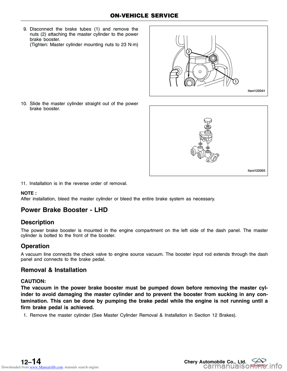
Downloaded from www.Manualslib.com manuals search engine 9. Disconnect the brake tubes (1) and remove thenuts (2) attaching the master cylinder to the power
brake booster.
(Tighten: Master cylinder mounting nuts to 23 N·m)
10. Slide the master cylinder straight out of the power brake booster.
11. Installation is in the reverse order of removal.
NOTE :
After installation, bleed the master cylinder or bleed the entire brake system as necessary.
Power Brake Booster - LHD
Description
The power brake booster is mounted in the engine compartment on the left side of the dash panel. The master
cylinder is bolted to the front of the booster.
Operation
A vacuum line connects the check valve to engine source vacuum. The booster input rod extends through the dash
panel and connects to the brake pedal.
Removal & Installation
CAUTION:
The vacuum in the power brake booster must be pumped down before removing the master cyl-
inder to avoid damaging the master cylinder and to prevent the booster from sucking in any con-
tamination. This can be done by pumping the brake pedal while the engine is not running until a
firm brake pedal is achieved.
1. Remove the master cylinder (See Master Cylinder Removal & Installation in Section 12 Brakes).
ON-VEHICLE SERVICE
LTSM120041
LTSM120005
12–14Chery Automobile Co., Ltd.
Page 1410 of 1903
Downloaded from www.Manualslib.com manuals search engine 2. Remove the spring-type cotter pin (2) and clevispin (1) from the brake booster rod (3).
3. Remove the nuts and bolts (1) attaching the power brake booster to the brake pedal bracket.
(Tighten: Brake pedal/Power brake booster mount-
ing nuts and bolts to 25 N·m)
4. Remove the brake pedal bracket.
5. Disconnect the vacuum hose (1) from the check valve on the power brake booster.
6. Slide the power brake booster (1) forward until its mounting studs clear the dash panel, then remove
it through the engine compartment.
7. Installation is in the reverse order of removal.
ON-VEHICLE SERVICE
BESM120009
LTSM120006
LTSM120004
BESM120028
12
12–15Chery Automobile Co., Ltd.
Page 1411 of 1903
Downloaded from www.Manualslib.com manuals search engine Power Brake Booster - RHD
Description
The power brake booster is mounted in the engine compartment on the right side of the dash panel. The master
cylinder is bolted to the front of the booster.
Operation
A vacuum line connects the check value to engine source vacuum. The booster input rod extends through the dash
panel and connects to the brake pedal.
Removal & Installation
CAUTION:
The vacuum in the power brake booster must be pumped down before removing the master cyl-
inder to avoid damaging the master cylinder and to prevent the booster from sucking in any con-
tamination. This can be done by pumping the brake pedal while the engine is not running until a
firm brake pedal is achieved.
1. Remove the master cylinder (See Master Cylinder Removal & Installation in Section 12 Brakes).
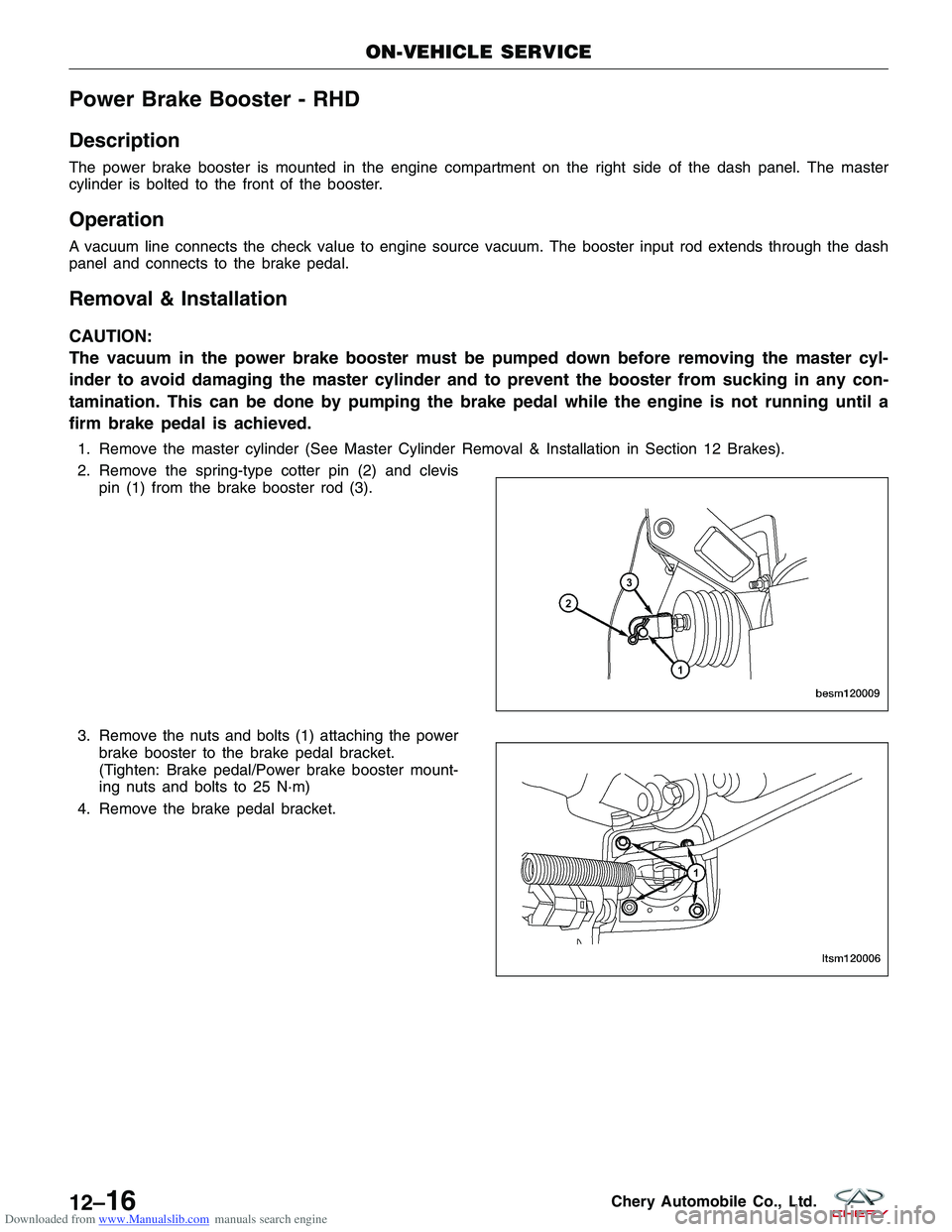
2. Remove the spring-type cotter pin (2) and clevispin (1) from the brake booster rod (3).
3. Remove the nuts and bolts (1) attaching the power brake booster to the brake pedal bracket.
(Tighten: Brake pedal/Power brake booster mount-
ing nuts and bolts to 25 N·m)
4. Remove the brake pedal bracket.
ON-VEHICLE SERVICE
BESM120009
LTSM120006
12–16Chery Automobile Co., Ltd.
Page 1412 of 1903
Downloaded from www.Manualslib.com manuals search engine 5. Disconnect the vacuum hose (1) from the checkvalve on the power brake booster.
6. Slide the power brake booster forward until its mounting studs clear the dash panel, then remove it through the engine compartment.
7. Installation is in the reverse order of removal.
ON-VEHICLE SERVICE
LTSM120004
12
12–17Chery Automobile Co., Ltd.
Page 1413 of 1903
Downloaded from www.Manualslib.com manuals search engine Front Brake Caliper
Description
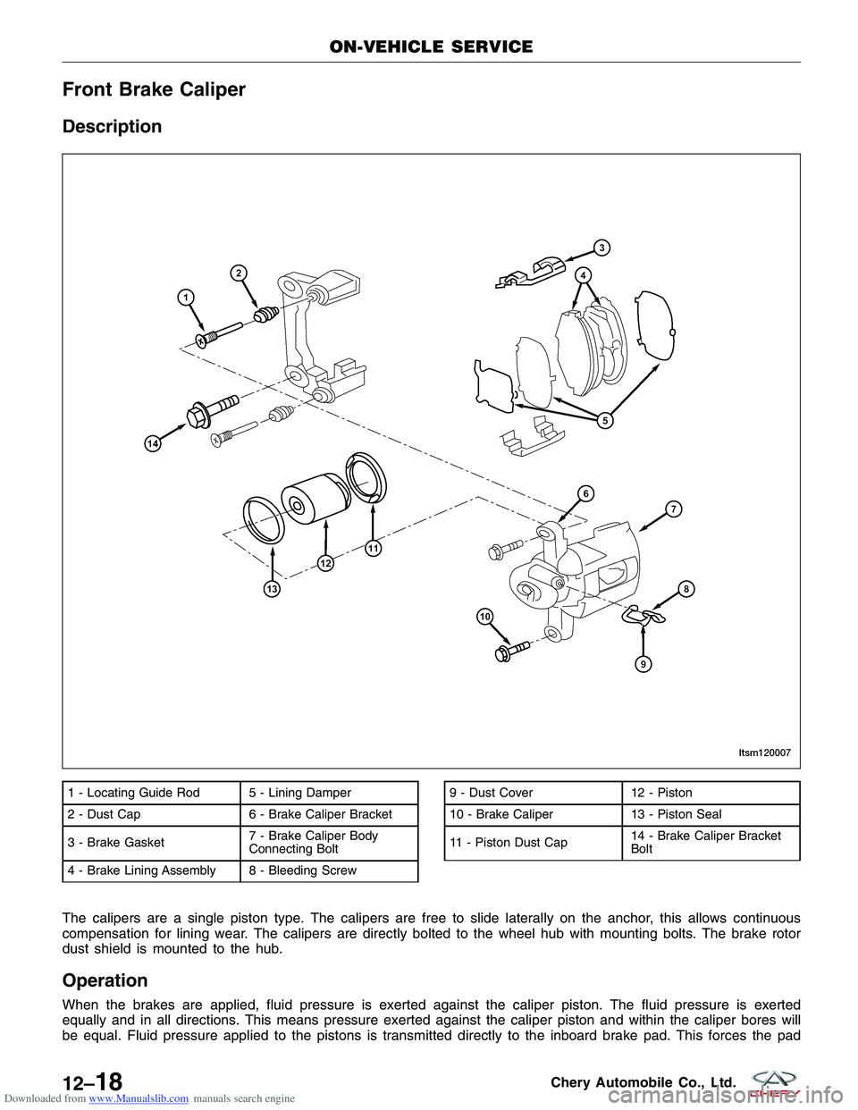
The calipers are a single piston type. The calipers are free to slide laterally on the anchor, this allows continuous
compensation for lining wear. The calipers are directly bolted to the wheel hub with mounting bolts. The brake rotor
dust shield is mounted to the hub.
Operation
When the brakes are applied, fluid pressure is exerted against the caliper piston. The fluid pressure is exerted
equally and in all directions. This means pressure exerted against the caliper piston and within the caliper bores will
be equal. Fluid pressure applied to the pistons is transmitted directly to the inboard brake pad. This forces the pad
1 - Locating Guide Rod 5 - Lining Damper
2 - Dust Cap 6 - Brake Caliper Bracket
3 - Brake Gasket7 - Brake Caliper Body
Connecting Bolt
4 - Brake Lining Assembly 8 - Bleeding Screw9 - Dust Cover 12 - Piston
10 - Brake Caliper 13 - Piston Seal
11 - Piston Dust Cap 14 - Brake Caliper Bracket
Bolt
ON-VEHICLE SERVICE
LTSM120007
12–18Chery Automobile Co., Ltd.