Page 49 of 192

3-3
MAINTENANCE INTERVALS
OIL STRAINERClean
●
FRAMEClean and inspect
●●
FUEL TANK, COCKClean and inspect
●●
BRAKESAdjust lever position and pedal
height
●●
Lubricate pivot point●●
Check brake disc surface●●
Check fluid level and leakage●●
Retighten brake disc bolts, cali-
per bolts, master cylinder bolts
and union bolts●●
Replace pads●
Replace brake fluid●Every one year
FRONT FORKS Inspect and adjust
●●
Replace oil●●Suspension oil "S1"
Replace oil seal
●
FRONT FORK OIL SEAL AND
DUST SEAL Clean and lube
●●Lithium base grease
PROTECTOR GUIDE Replace
●
REAR SHOCK ABSORBERInspect and adjust
●●
Lube●
(After rain
ride)
●Molybdenum disulfide grease
Replace spring seat
●Every one year
Retighten
●●
DRIVE CHAIN GUIDE AND
ROLLERS Inspect
●●
SWINGARMInspect, lube and retighten
●●Molybdenum disulfide grease
RELAY ARM, CONNECTING
ROD Inspect, lube and retighten
●●Molybdenum disulfide grease
STEERING HEAD Inspect free play and retighten
●●
Clean and lube●Lithium base grease
Replace bearing
●
Item After
break-
in Every
race
Every third
(or 500 km) Every
fifth (or 1,000 km)
As re-
quired Remarks
Page 50 of 192
3-4
MAINTENANCE INTERVALS
TIRE, WHEELSInspect air pressure, wheel run-
out, tire wear and spoke loose-
ness
●●
Retighten sprocket bolt●●
Inspect bearings●
Replace bearings●
Lubricate●Lithium base grease
THROTTLE, CONTROL CABLE Check routing and connection
●●
Lubricate●●Yamaha cable lube or SAE 10W-30
motor oil
Inspect and clean (throttle ca-
ble)
●●Inspect dirt and wear on the throttle
cable on the carburetor side.
HOT STARTER, CLUTCH LEVER Inspect free play
●
Item After
break-
in Every
race
Every third
(or 500 km) Every
fifth (or 1,000 km)
As re-
quired Remarks
Page 51 of 192

3-5
PRE-OPERATION INSPECTION AND MAINTENANCE
PRE-OPERATION INSPECTION AND MAINTENANCE
Before riding for break-in operation, practice or a race, make sure the machine is in good operating condition.
Before using this machine, check the following points.
GENERAL INSPECTION AND MAINTENANCEItem RoutinePage
Coolant Check that coolant is filled up to the radiator cap. Check the cool-
ing system for leakage. P.3-6 – 7
Fuel Check that a fresh gasoline is filled in the fuel tank. Check the fuel
line for leakage. P.1-8 – 9
Engine oil Check that the oil level is correct. Check the crankcase and oil line
for leakage. P.3-8 – 10
Gear shifter and clutch Check that gears can be shifted correctly in order and that the
clutch operates smoothly. P.3-7
Throttle grip/Housing Check that the throttle grip operation and free play are correctly
adjusted. Lubricate the throttle grip and housing, if necessary. P.3-7 – 8
Brakes Check the play of front brake and effect of front and rear brake. P.3-14 – 16
Drive chain Check drive chain slack and alignment. Check that the drive chain
is lubricated properly. P.3-17
Wheels Check for excessive wear and tire pressure. Check for loose
spokes and have no excessive play. P.3-20
Steering Check that the handlebar can be turned smoothly and have no ex-
cessive play. P.3-20 – 21
Front forks and rear shock
absorber Check that they operate smoothly and there is no oil leakage.
P.3-18 – 20
Cables (wires) Check that the clutch and throttle cables move smoothly. Check
that they are not caught when the handlebars are turned or when
the front forks travel up and down.
—
Exhaust pipe Check that the exhaust pipe is tightly mounted and has no cracks. P.4-3 – 4
Rear wheel sprocket Check that the rear wheel sprocket tightening bolt is not loose. P.3-16 – 17
Lubrication Check for smooth operation. Lubricate if necessary. P.3-22
Bolts and nuts Check the chassis and engine for loose bolts and nuts. P.1-11
Lead connectors Check that the CDI magneto, CDI unit, and ignition coil are con-
nected tightly. P.1-3
Settings Is the machine set suitably for the condition of the racing course
and weather or by taking into account the results of test runs be-
fore racing? Are inspection and maintenance completely done?
P.7-1 – 10
Page 52 of 192

3-6
ENGINE
ENGINE
CHECKING THE COOLANT LEVEL
Do not remove the radiator cap
"1", drain bolt and hoses when the
engine and radiator are hot. Scald-
ing hot fluid and steam may be
blown out under pressure, which
could cause serious injury. When
the engine has cooled, place a
thick towel over the radiator cap,
slowly rotate the cap counter-
clockwise to the detent. This pro-
cedure allows any residual
pressure to escape. When the
hissing sound has stopped, press
down on the cap while turning
counterclockwise and remove it.
Hard water or salt water is harmful
to the engine parts. You may use
distilled water, if you can't get soft
water.
1. Place the machine on a level place, and hold it in an upright po-
sition.
2. Remove: • Radiator cap
3. Check: • Coolant level "a"Coolant level low
→Add coolant.
1. Radiator
CHANGING THE COOLANT
Do not remove the radiator cap
when the engine is hot.
Take care so that coolant does not
splash on painted surfaces. If it
splashes, wash it away with water.
1. Place a container under the en- gine.
2. Remove: • Coolant drain bolt "1"
3. Remove: •Radiator capDrain the coolant completely.
4. Clean:
• Cooling systemThoroughly flush the cooling sys-
tem with clean tap water.
5. Install: • Copper washer
• Coolant drain bolt
6. Fill: •Radiator
•EngineTo specified level.
• Do not mix more than one type of ethylene glycol antifreeze con-
taining corrosion inhibitors for
aluminum engine.
• Do not use water containing im-
purities or oil.
Handling notes of coolant:
The coolant is harmful so it should be
handled with special care.
• When coolant splashes to your eye.
Thoroughly wash your eye with
water and see your doctor.
• When coolant splashes to your
clothes.
Quickly wash it away with water
and then with soap.
• When coolant is swallowed. Quickly make him vomit and take
him to a doctor.
7. Install:•Radiator capStart the engine and warm it up
for a several minutes.
8. Check:
• Coolant levelCoolant level low
→Add coolant.
CHECKING THE RADIATOR CAP
1. Inspect: • Seal (radiator cap) "1"
• Valve and valve seat "2"
Crack/damage
→Replace.
Exist fur deposits "3"
→Clean or
replace.
CHECKING THE RADIATOR CAP
OPENING PRESSURE
1. Attach: • Radiator cap tester "1" and adapt-
er "2"
Apply water on the radiator cap seal.
3. Radiator cap
Coolant drain bolt: 10 Nm (1.0 m•kg, 7.2
ft•lb)
Recommended coolant: High quality ethylene
glycol anti-freeze con-
taining anti-corrosion
for aluminum engine
Coolant "1" and water
(soft water) "2" mixing ra-
tio: 50%/50%
Coolant capacity:
0.99 L (0.87 Imp qt, 1.05
US qt)
Radiator cap tester:YU-24460-01/90890-
01325
Radiator cap tester
adapter: YU-33984/90890-01352
Page 53 of 192

3-7
ENGINE
2. Apply the specified pressure.
3. Inspect:•PressureImpossible to maintain the speci-
fied pressure for 10 seconds
→
Replace.
CHECKING THE COOLING
SYSTEM
1. Inspect: • Coolant level
2. Attach: • Radiator cap tester "1" and adapt-
er "2"
3. Apply the specified pressure.
�Œ Do not apply pressure more than
specified pressure.
• Radiator should be filled fully.
4. Inspect: •Pressure
Impossible to maintain the speci-
fied pressure for 10 seconds
→
Repair.
• Radiator "1"
• Radiator hose joint "2" Coolant leakage
→Repair or re-
place.
• Radiator hose "3" Swelling
→Replace. ADJUSTING THE CLUTCH CABLE
FREE PLAY
1. Check:
• Clutch lever free play "a"
Out of specification
→Adjust.
2. Adjust: • Clutch lever free play
Clutch lever free play adjustment
steps:
a. Loosen the locknuts "1".
b. Turn the adjuster "2" until free play "a" is within the specified lim-
its.
c. Tighten the locknuts.
�Œ Before adjustment, expose the ad-
juster by moving the boot "3" and
cap "4" away.
• Make minute adjustment on the le- ver side using the adjuster "5".
• After adjustment, check proper op-
eration of clutch lever.
3. Install:•Cap "1"
•Boot "2"
Place the tip "a" of the cap in the boot.
ADJUSTING THE THROTTLE
CABLE FREE PLAY
1. Check:• Throttle grip free play "a"
Out of specification
→Adjust.
2. Adjust: • Throttle grip free play
Throttle grip free play adjustment
steps:
a. Slide the adjuster cover.
b. Loosen the locknut "1".
c. Turn the adjuster "2" until the specified free play is obtained.
d. Tighten the locknut.
Before adjusting the throttle cable
free play, the engine idle speed
should be adjusted.
After adjusting the throttle cable
free play, start the engine and turn
the handlebar to right and left and
make sure that the engine idling
does not run faster.
LUBRICATING THE THROTTLE
1. Remove: • Cover (throttle cable cap) "1"
• Cover (grip cap) "2"
• Throttle grip cap "3"
Radiator cap opening
pressure:
110 kPa (1.1 kg/cm
2,
15.6 psi)
Radiator cap tester: YU-24460-01/90890-
01325
Radiator cap tester
adapter: YU-33984/90890-01352
Standard pressure: 180 kPa (1.8 kg/cm
2,
25.6 psi)
Clutch lever free play "a"
: 8–13 mm (0.31–0.51 in)
Locknut: 4 Nm (0.4 m•kg, 2.9
ft•lb)Throttle grip free play
"a":3–5 mm (0.12–0.20 in)
Locknut: 4 Nm (0.4 m•kg, 2.9
ft•lb)
Page 54 of 192

• Cover (grip cap)
• Cover (throttle cable cap)
ADJUS")
3-8
ENGINE
2. Apply:• Lithium soap base greaseOn the throttle cable end "a".
3. Install: • Throttle grip cap
• Screw (throttle grip cap)
• Cover (grip cap)
• Cover (throttle cable cap)
ADJUSTING THE HOT STARTER
LEVER FREE PLAY
1. Check: • Hot starter lever free play "a"Out of specification
→Adjust.
2. Adjust: • Hot starter lever free play
Hot starter lever free play adjust-
ment steps:
a. Loosen the locknut "1".
b. Turn the adjuster "2" until free play "a" is within the specified lim-
its.
c. Tighten the locknut.
After adjustment, check proper oper-
ation of hot starter.
CLEANING THE AIR FILTER
ELEMENT
Proper air filter maintenance is the
biggest key to preventing premature
engine wear and damage.
Never run the engine without the
air filter element in place; this
would allow dirt and dust to enter
the engine and cause rapid wear
and possible engine damage.
1. Remove: •Seat
• Fitting bolt "1"
•Washer "2"
• Air filter element "3"
• Air filter guide "4"
2. Clean: • Air filter elementClean them with solvent.
After cleaning, remove the remaining
solvent by squeezing the element.
• Do not twist the element when
squeezing the element.
• Leaving too much of solvent in
the element may result in poor
starting.
3. Inspect:• Air filter element
Damage
→Replace.
4. Apply: • Foam-air-filter oil or equivalent oil
to the element
Squeeze out the excess oil. Element
should be wet but not dripping.
5. Install:• Air filter guide "1"
Align the projection "a" on filter guide
with the hole "b" in air filter element.
6. Apply:• Lithium soap base grease On the matching surface "a" on air
filter element.
7. Install: • Air filter element "1"
• Washer
• Fitting bolt
Align the projection "a" on filter guide
with the hole "b" in air filter case.
CHECKING THE ENGINE OIL
LEVEL
1. Start the engine, warm it up for several minutes, and then turn off
the engine and wait for five min-
utes.
2. Place the machine on a level place and hold it up on upright po-
sition by placing the suitable
stand under the engine.
3. Inspect:
• Oil levelOil should be up to the full level in
the check window "1".
Level check window is not full.
→
Add 0.2 L (0.18 Imp qt, 0.21 US
qt) of oil.
Screw (throttle grip cap):
4 Nm (0.4 m•kg, 2.9
ft•lb)
Hot starter lever free play
"a": 3–6 mm (0.12–0.24 in)
Locknut: 4 Nm (0.4 m•kg, 2.9
ft•lb)
Fitting bolt:
2 Nm (0.2 m•kg, 1.4
ft•lb)
Page 55 of 192

• Do not add any chemical addi-tives. Engine oil also lubricates
the clutch and additives could
cause clutch slippage.
• Do not allow foreign material to
enter the")
3-9
ENGINE
(For USA and CDN)
• Do not add any chemical addi-tives. Engine oil also lubricates
the clutch and additives could
cause clutch slippage.
• Do not allow foreign material to
enter the crankcase.
(Except for USA and CDN)
• Do not add any chemical addi-tives or use oils with a grade of
CD "a" or higher.
• Do not use oils labeled "ENERGY CONSERVING II" "b" or higher.
Engine oil also lubricates the
clutch and additives could cause
clutch slippage.
• Do not allow foreign material to enter the crankcase.
4. Install:• Oil tank cap
5. Start the engine and let it warm up
for several minutes.
6. Turn off the engine and inspect the oil level once again.
Wait a few minutes until the oil settles
before inspecting the oil level.
CHANGING THE ENGINE OIL
1. Start the engine and warm it up
for several minutes, and then turn
off the engine and wait for five
minute.
2. Place the machine on a level place and hold it on upright posi-
tion by placing the suitable stand
under the engine.
3. Place a suitable container under the engine.
4. Remove: • Lower engine guard "1"
• Bolt (oil tank) "2"
•Washer "3"
• Oil filler cap "4"
• Oil tank drain bolt "5"
• Crankcase oil drain bolt "6"
• Oil filter element drain bolt "7"Drain the crankcase and oil tank
of its oil. 5. Remove:
• Oil hose clamp "1"
• Bolt (oil hose)
•Oil hose "2"
• Oil strainer "3"
6. Inspect: • Oil strainerClogged
→Blow.
7. If the oil filter is to be replaced dur- ing this oil change, remove the fol-
lowing parts and reinstall them.
Replacement steps:
a. Remove the oil filter element cov-
er "1" and oil filter element "2".
b. Check the O-rings "3", if cracked or damaged, replace them with a
new one.
c. Install the oil filter element and oil filter element cover.
8. Install:• O-ring "1"
• Oil strainer "2"
•Oil hose
• Bolt (oil hose)
Recommended oil:
Yamalube 4,
SAE10W30 or
SAE20W40
Yamalube 4-R,
SAE10W50
API service SG type or
higher, JASO standard
MA
Recommended oil: SAE10W30,
SAE10W40,
SAE15W40, SAE20W40
or SAE20W50
API service SG type or
higher, JASO standard
MA
Oil filter element cover:
10 Nm (1.0 m•kg, 7.2
ft•lb)
Oil strainer: 9 Nm (0.9 m•kg, 6.5
ft•lb)
Bolt (oil hose): 8 Nm (0.8 m•kg, 5.8
ft•lb)
Page 56 of 192

3-10
ENGINE
• Oil hose clamp
9. Install: • Copper washer
• Oil filter element drain bolt
• Crankcase oil drain bolt
• Oil tank drain bolt
• Lower engine guard
10. Fill: • Engine oil
11. Check: • Oil leakage
12. Install: • Oil filler cap
• Washer (oil tank) • Bolt (oil tank)
13. Check: • Engine oil level
CHECKING THE OIL PRESSURE
1. Check: • Oil pressure
Checking steps:
a. Slightly loosen the oil pressure check bolt "1".
b. Start the engine and keep it idling until oil starts to seep from the oil
pressure check bolt. If no oil
comes out after one minute, turn
the engine off so it will not seize.
c. Check oil passages and oil pump for damage or leakage.
d. Start the engine after solving the
problem(s) and recheck the oil
pressure.
e. Tighten the oil pressure check
bolt.
ADJUSTING THE PILOT SCREW
1. Adjust:• Pilot screw "1"
Adjustment steps:
To optimize the fuel flow at a smaller
throttle opening, each machine's pilot
screw has been individually set at the
factory. Before adjusting the pilot
screw, turn it in fully and count the
number of turns. Record this number
as the factory-set number of turns
out.
a. Turn in the pilot screw until it is lightly seated.
b. Turn out the pilot screw by the factory-set number of turns.
ADJUSTING THE ENGINE IDLING
SPEED
1. Start the engine and thoroughly warm it up.
2. Adjust: • Engine idling speed
Adjustment steps:
a. Adjust the pilot screw. Refer to "ADJUSTING THE PI-
LOT SCREW" section.
b. Turn the throttle stop screw "1"
until the specified engine idling
speed.
Using a digital engine tachometer for
idle speed adjustment, detect the en-
gine idling speed by bringing the
sensing element "c" of the engine ta-
chometer close to the ignition coil "2".
Oil hose clamp:2 Nm (0.2 m•kg, 1.4
ft•lb)
Oil filter element drain
bolt: 10 Nm (1.0 m•kg, 7.2
ft•lb)
Crankcase oil drain bolt: 20 Nm (2.0 m•kg, 14
ft•lb)
Oil tank drain bolt: 18 Nm (1.8 m•kg, 13
ft•lb)
Lower engine guard: 10 Nm (1.0 m•kg, 7.2
ft•lb)
Oil quantity: Periodic oil change:1.05 L (0.92 Imp qt,
1.11 US qt)
With oil filter replace-
ment: 1.15 L (1.01 Imp qt,
1.22 US qt)
Total amount:
1.30 L (1.14 Imp qt,
1.37 US qt)Bolt (oil tank): 7 Nm (0.7 m•kg, 5.1
ft•lb)
Oil pressure check bolt: 10 Nm (1.0 m•kg, 7.2
ft•lb)
Pilot screw (example): 2-3/8 turns out
To increase idle speed→Turn the
throttle stop screw "1" in "a".
To decrease idle speed
→Turn
the throttle stop screw "1" out
"b".
Engine idling speed:1,900–2,100 r/min
 1
1 2
2 3
3 4
4 5
5 6
6 7
7 8
8 9
9 10
10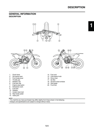 11
11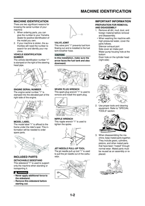 12
12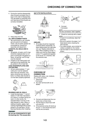 13
13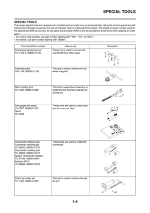 14
14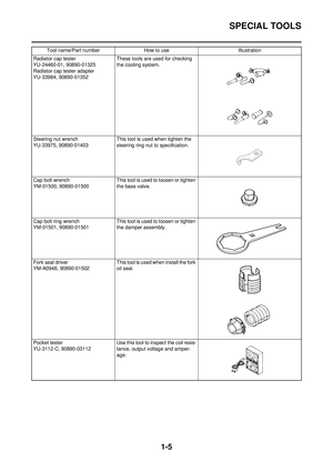 15
15 16
16 17
17 18
18 19
19 20
20 21
21 22
22 23
23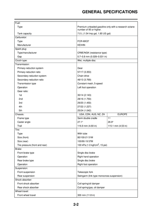 24
24 25
25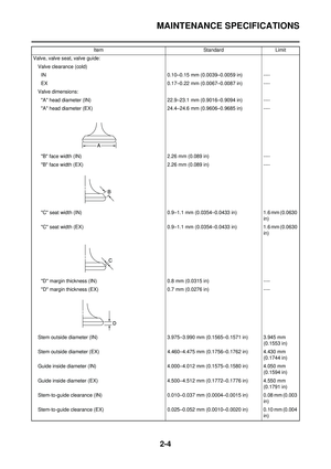 26
26 27
27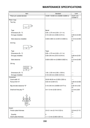 28
28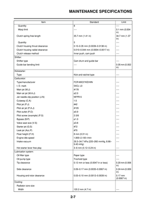 29
29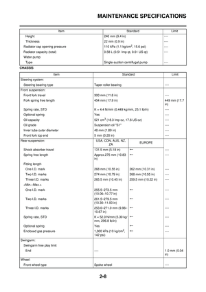 30
30 31
31 32
32 33
33 34
34 35
35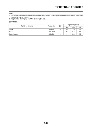 36
36 37
37 38
38 39
39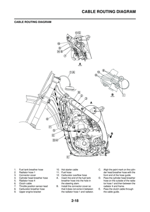 40
40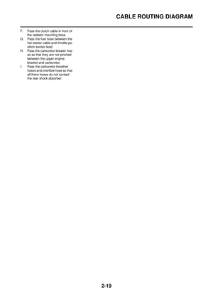 41
41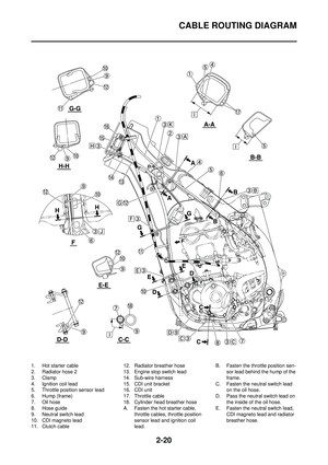 42
42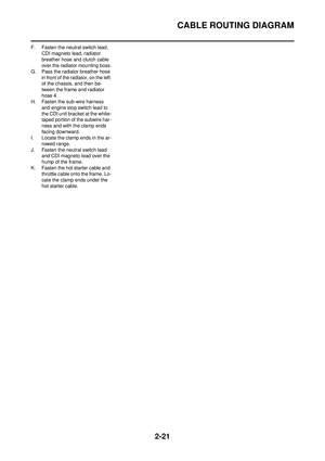 43
43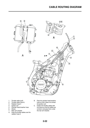 44
44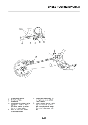 45
45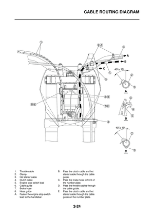 46
46 47
47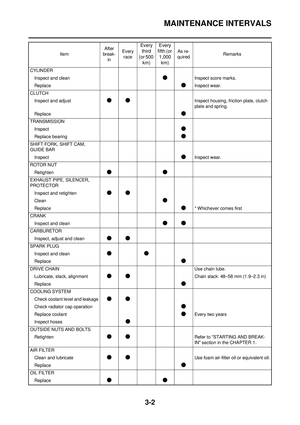 48
48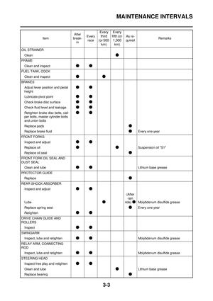 49
49 50
50 51
51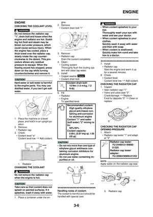 52
52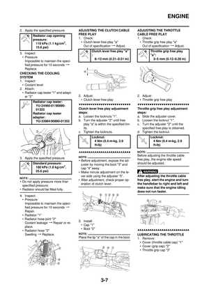 53
53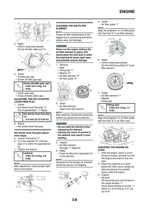 54
54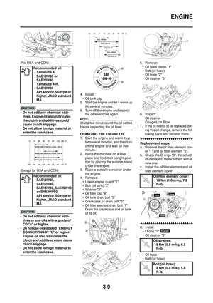 55
55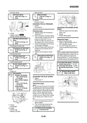 56
56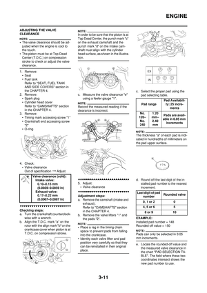 57
57 58
58 59
59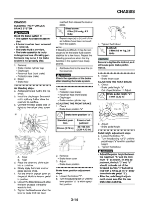 60
60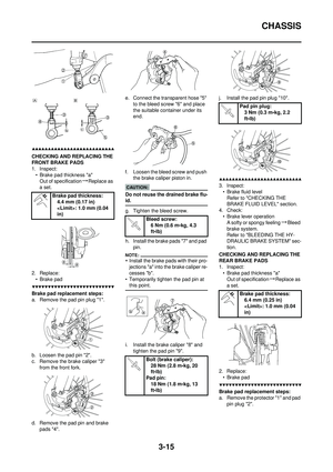 61
61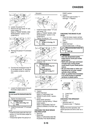 62
62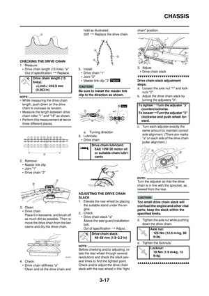 63
63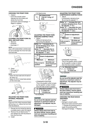 64
64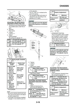 65
65 66
66 67
67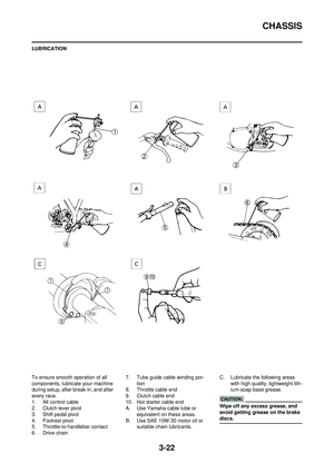 68
68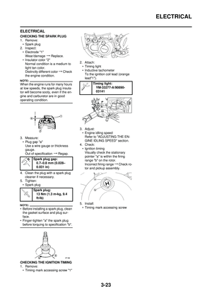 69
69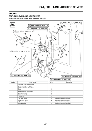 70
70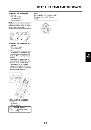 71
71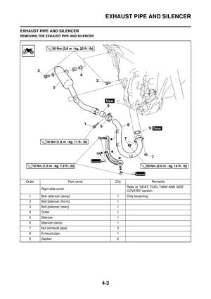 72
72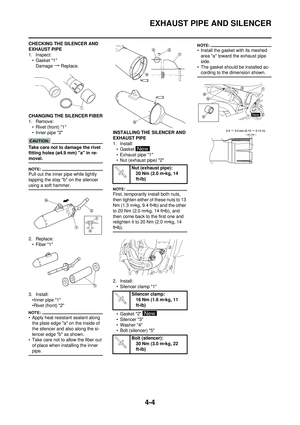 73
73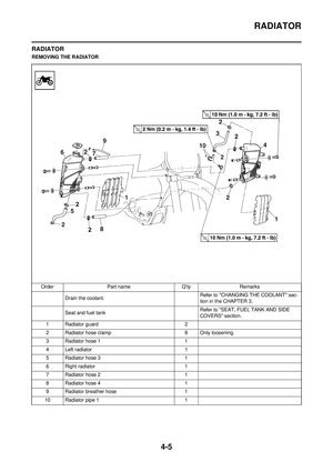 74
74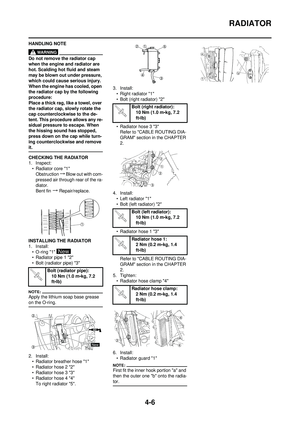 75
75 76
76 77
77 78
78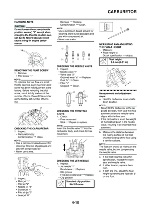 79
79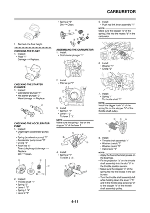 80
80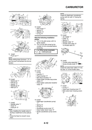 81
81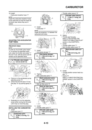 82
82 83
83 84
84 85
85 86
86 87
87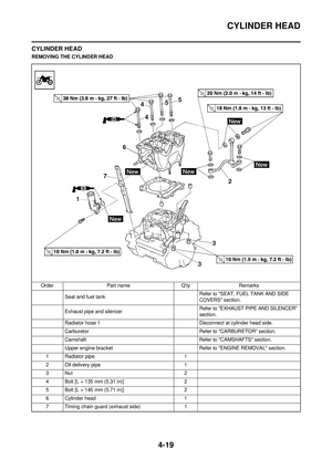 88
88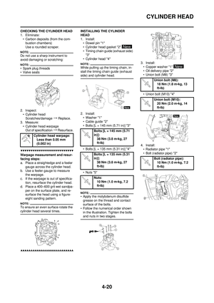 89
89 90
90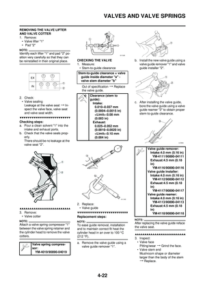 91
91 92
92 93
93 94
94 95
95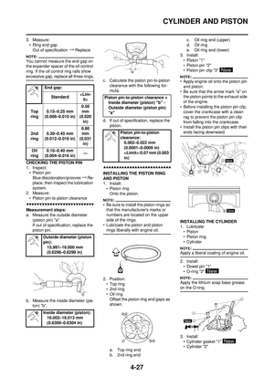 96
96 97
97 98
98 99
99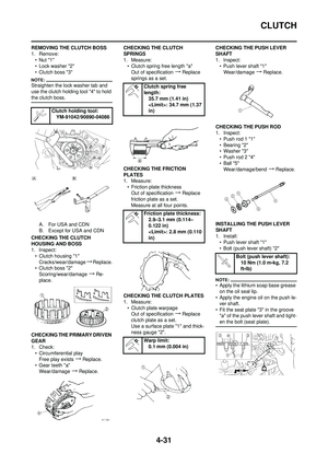 100
100 101
101 102
102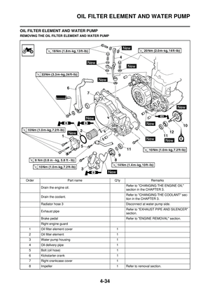 103
103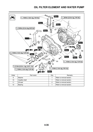 104
104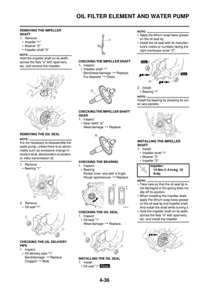 105
105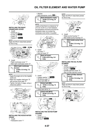 106
106 107
107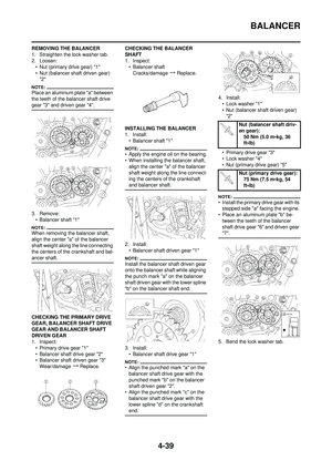 108
108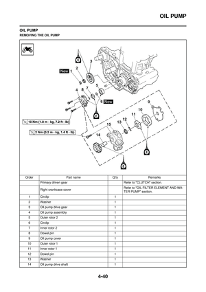 109
109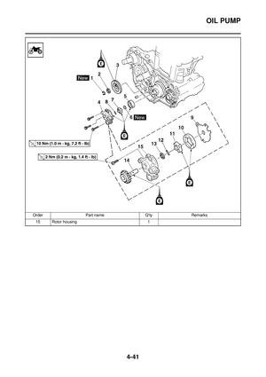 110
110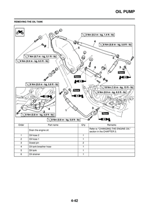 111
111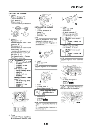 112
112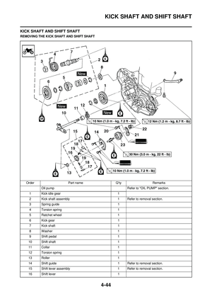 113
113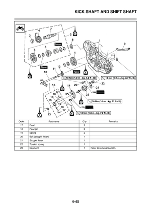 114
114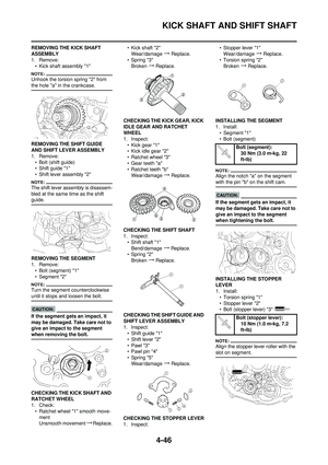 115
115 116
116 117
117 118
118 119
119 120
120 121
121 122
122 123
123 124
124 125
125 126
126 127
127 128
128 129
129 130
130 131
131 132
132 133
133 134
134 135
135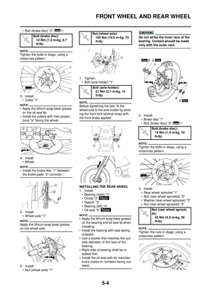 136
136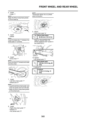 137
137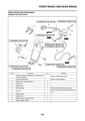 138
138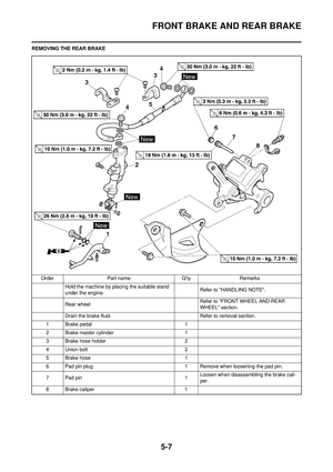 139
139 140
140 141
141 142
142 143
143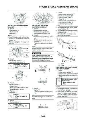 144
144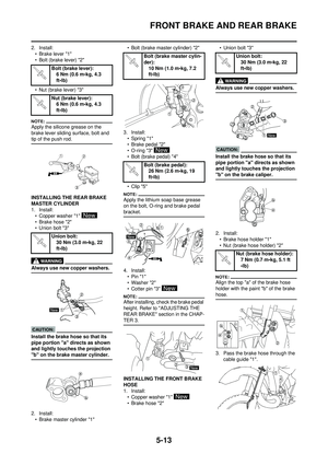 145
145 146
146 147
147 148
148 149
149 150
150 151
151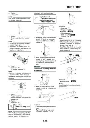 152
152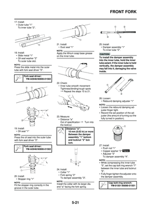 153
153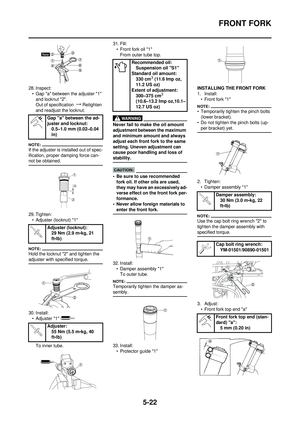 154
154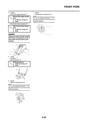 155
155 156
156 157
157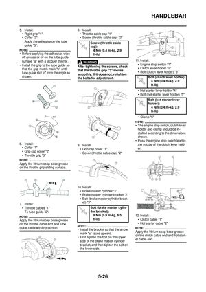 158
158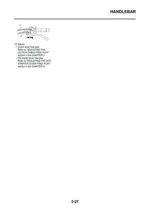 159
159 160
160 161
161 162
162 163
163 164
164 165
165 166
166 167
167 168
168 169
169 170
170 171
171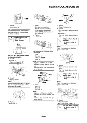 172
172 173
173 174
174 175
175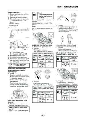 176
176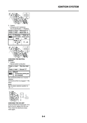 177
177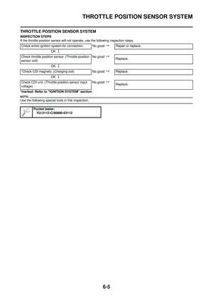 178
178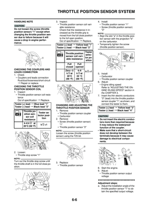 179
179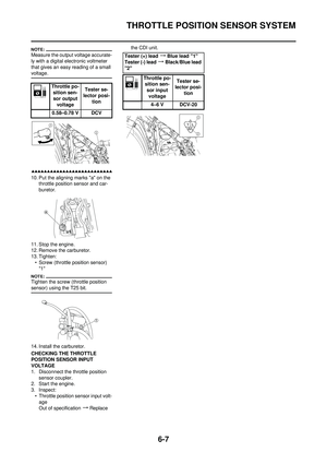 180
180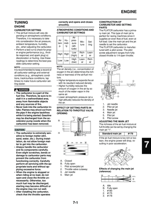 181
181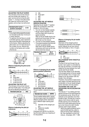 182
182 183
183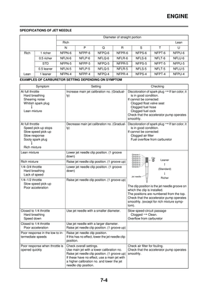 184
184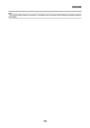 185
185 186
186 187
187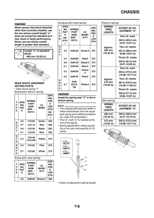 188
188 189
189 190
190 191
191