2008 YAMAHA YZ250F steering
[x] Cancel search: steeringPage 10 of 192

CONTENTS
CHAPTER 1
GENERAL INFOR-
MATION
DESCRIPTION ................. 1-1
MACHINE
IDENTIFICATION ............. 1-2
INCLUDED PARTS .......... 1-2
IMPORTANT
INFORMATION................. 1-2
CHECKING OF
CONNECTION .................. 1-3
SPECIAL TOOLS ............. 1-4
CONTROL FUNCTIONS .. 1-8
STARTING AND
BREAK-IN ........................ 1-8
TORQUE-CHECK
POINTS........................... 1-11
CLEANING AND
STORAGE ...................... 1-12
CHAPTER 2
SPECIFICATIONS
GENERAL
SPECIFICATIONS ............ 2-1
MAINTENANCE
SPECIFICATIONS ............ 2-3
TIGHTENING
TORQUES ...................... 2-10
LUBRICATION
DIAGRAMS .................... 2-16
CABLE ROUTING
DIAGRAM ....................... 2-18
CHAPTER 3
REGULAR INSPEC-
TION AND AD-JUSTMENTS
MAINTENANCE
INTERVALS ...................... 3-1
PRE-OPERATION
INSPECTION AND
MAINTENANCE................ 3-5
ENGINE ............................ 3-6
CHASSIS ........................ 3-14
ELECTRICAL ................. 3-23
CHAPTER 4 ENGINE
SEAT, FUEL TANK AND
SIDE COVERS.................. 4-1
EXHAUST PIPE AND
SILENCER ........................ 4-3
RADIATOR ....................... 4-5
CARBURETOR................. 4-7
CAMSHAFTS.................. 4-14
CYLINDER HEAD........... 4-19
VALVES AND VALVE
SPRINGS ........................ 4-21
CYLINDER AND
PISTON ........................... 4-25
CLUTCH ......................... 4-29
OIL FILTER ELEMENT
AND WATER PUMP ....... 4-34
BALANCER .................... 4-38
OIL PUMP ....................... 4-40
KICK SHAFT AND
SHIFT SHAFT ................. 4-44
CDI MAGNETO............... 4-49
ENGINE REMOVAL ....... 4-51
CRANKCASE AND
CRANKSHAFT ............... 4-55
TRANSMISSION, SHIFT
CAM AND SHIFT
FORK .............................. 4-61
CHAPTER 5CHASSIS
FRONT WHEEL AND
REAR WHEEL ..................5-1
FRONT BRAKE AND
REAR BRAKE ..................5-6
FRONT FORK ................. 5-16
HANDLEBAR..................5-24
STEERING ......................5-28
SWINGARM ....................5-32
REAR SHOCK
ABSORBER ....................5-37
CHAPTER 6
ELECTRICAL
ELECTRICAL
COMPONENTS AND
WIRING DIAGRAM ...........6-1
IGNITION SYSTEM...........6-2
THROTTLE POSITION
SENSOR SYSTEM ...........6-5
CHAPTER 7
TUNING
ENGINE.............................7-1
CHASSIS ..........................7-6
Page 12 of 192

1-2
MACHINE IDENTIFICATION
MACHINE IDENTIFICATION
There are two significant reasons for
knowing the serial number of your
machine:
1. When ordering parts, you can give the number to your Yamaha
dealer for positive identification of
the model you own.
2. If your machine is stolen, the au-
thorities will need the number to
search for and identify your ma-
chine.
VEHICLE IDENTIFICATION
NUMBER
The vehicle identification number "1"
is stamped on the right of the steering
head pipe.
ENGINE SERIAL NUMBER
The engine serial number "1" is
stamped into the elevated part of the
right-side of the engine.
MODEL LABEL
The model label "1" is affixed to the
frame under the rider's seat. This in-
formation will be needed to order
spare parts.
INCLUDED PARTS
DETACHABLE SIDESTAND
This sidestand "1" is used to support
only the machine when standing or
transporting it.
• Never apply additional force to the sidestand.
• Remove this sidestand before
starting out.
VALVE JOINT
This valve joint "1" prevents fuel from
flowing out and is installed to the fuel
tank breather hose.
In this installation, make sure the
arrow faces the fuel tank and also
downward.
SPARK PLUG WRENCH
This spark plug wrench "1" is used to
remove and install the spark plug.
NIPPLE WRENCH
This nipple wrench "1" is used to
tighten the spoke.
JET NEEDLE PULL-UP TOOL
The jet needle pull-up tool "1" is used
to pull the jet needle out of the carbu-
retor.
IMPORTANT INFORMATION
PREPARATION FOR REMOVAL
AND DISASSEMBLY
1. Remove all dirt, mud, dust, and foreign material before removal
and disassembly.
• When washing the machine with high pressured water, cover the
parts follows.
Silencer exhaust port
Side cover air intake port
Water pump housing hole at the
bottom
Drain hole on the cylinder head
(right side)
2. Use proper tools and cleaning equipment. Refer to "SPECIAL
TOOLS" section.
3. When disassembling the ma- chine, keep mated parts together.
They include gears, cylinders,
pistons, and other mated parts
that have been "mated" through
normal wear. Mated parts must
be reused as an assembly or re-
placed.
Page 15 of 192

1-5
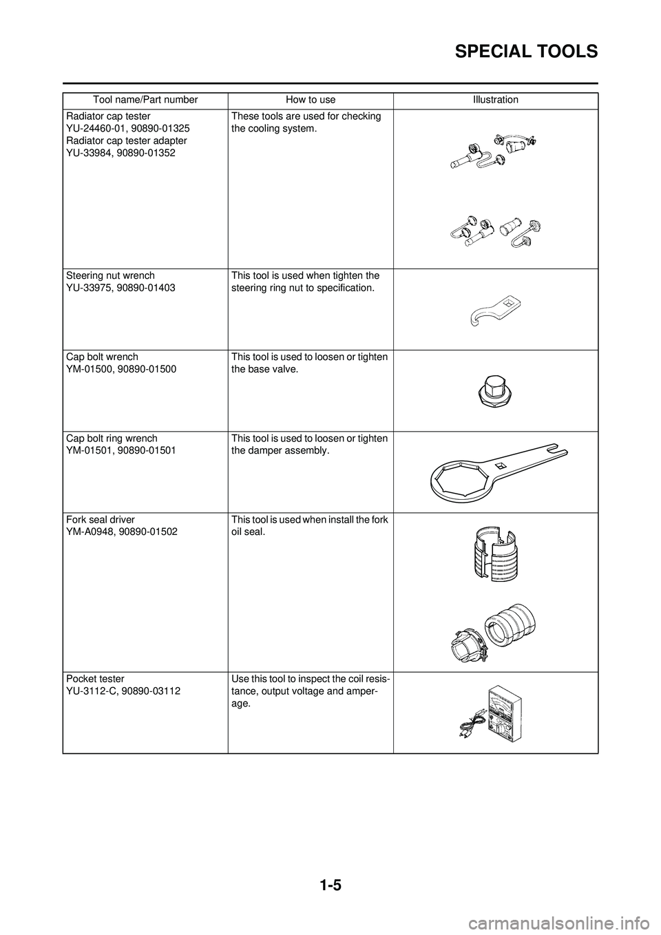
SPECIAL TOOLS
Radiator cap tester
YU-24460-01, 90890-01325
Radiator cap tester adapter
YU-33984, 90890-01352These tools are used for checking
the cooling system.
Steering nut wrench
YU-33975, 90890-01403 This tool is used when tighten the
steering ring nut to specification.
Cap bolt wrench
YM-01500, 90890-01500 This tool is used to loosen or tighten
the base valve.
Cap bolt ring wrench
YM-01501, 90890-01501 This tool is used to loosen or tighten
the damper assembly.
Fork seal driver
YM-A0948, 90890-01502 This tool is used when install the fork
oil seal.
Pocket tester
YU-3112-C, 90890-03112 Use this tool to inspect the coil resis-
tance, output voltage and amper-
age.
Tool name/Part number
How to useIllustration
Page 21 of 192

1-11
TORQUE-CHECK POINTS
TORQUE-CHECK POINTS
Concerning the tightening torque, refer to "TIGHTENING TORQUES" section in the CHAPTER 2.
Frame constructionFrame to rear frame
Combined seat and fuel tank Fuel tank to frame
Exhaust system Silencer to rear frame
Engine mounting Frame to engine
Engine bracket to engine
Engine bracket to frame
Steering Steering stem to handlebar Steering stem to frame
Steering stem to upper bracket
Upper bracket to handlebar
Suspension Front Steering stem to front fork Front fork to upper bracket
Front fork to lower bracket
Rear For link type Assembly of links
Link to frame
Link to rear shock absorber
Link to swingarm
Installation of rear shock absorber Rear shock absorber to frame
Installation of swingarm Tightening of pivot shaft
Wheel Installation of wheel Front Tightening of wheel axle
Tightening of axle holder
Rear Tightening of wheel axle Wheel to rear wheel sprocket
Brake Front Brake caliper to front fork
Brake disc to wheel
Tightening of union bolt
Brake master cylinder to handlebar
Tightening of bleed screw
Tightening of brake hose holder
Rear Brake pedal to frame Brake disc to wheel
Tightening of union bolt
Brake master cylinder to frame
Tightening of bleed screw
Tightening of brake hose holder
Fuel system Fuel tank to fuel cock
Lubrication system Tightening of oil hose clamp
Page 30 of 192

2-8
MAINTENANCE SPECIFICATIONS
CHASSISHeight
240 mm (9.4 in)----
Thickness 22 mm (0.9 in)----
Radiator cap opening pressure 110 kPa (1.1 kg/cm
2, 15.6 psi)----
Radiator capacity (total) 0.58 L (0.51 Imp qt, 0.61 US qt)----
Water pump Type Single-suction centrifugal pump----
Item
StandardLimit
Item StandardLimit
Steering system: Steering bearing type Taper roller bearing----
Front suspension: Front fork travel 300 mm (11.8 in)----
Fork spring free length 454 mm (17.9 in)449 mm (17.7
in)
Spring rate, STD K = 4.4 N/mm (0.449 kg/mm, 25.1 lb/in)----
Optional spring Yes----
Oil capacity 521 cm
3 (18.3 lmp oz, 17.6 US oz)----
Oil grade Suspension oil "S1"----
Inner tube outer diameter 48 mm (1.89 in)----
Front fork top end 5 mm (0.20 in)----
Rear suspension: USA, CDN, AUS, NZ,
ZA EUROPE
Shock absorber travel 131.5 mm (5.18 in)
←----
Spring free length Approx.275 mm (10.83 in)
←----
Fitting length One I.D. mark 268 mm (10.55 in) 262 mm (10.31 in) ----
Two I.D. marks 274 mm (10.79 in) 268 mm (10.55 in) ----
Three I.D. marks 265.5 mm (10.45 in) 259.5 mm (10.22 in) ----
←----
Two I.D. marks 261.5–279.5 mm
(10.30–11.00 in)
←----
Three I.D. marks 253.0–271.0 mm (9.96–
10.67 in)
←----
Spring rate, STD K = 52.0 N/mm (5.30 kg/ mm, 296.8 lb/in)
←----
Optional spring Yes
←----
Enclosed gas pressure 1,000 kPa (10 kg/cm
2,
142 psi)←----
Swingarm: Swingarm free play limitEnd ---- 1.0 mm (0.04 in)
Wheel: Front wheel type Spoke wheel----
Page 34 of 192

2-12
TIGHTENING TORQUES
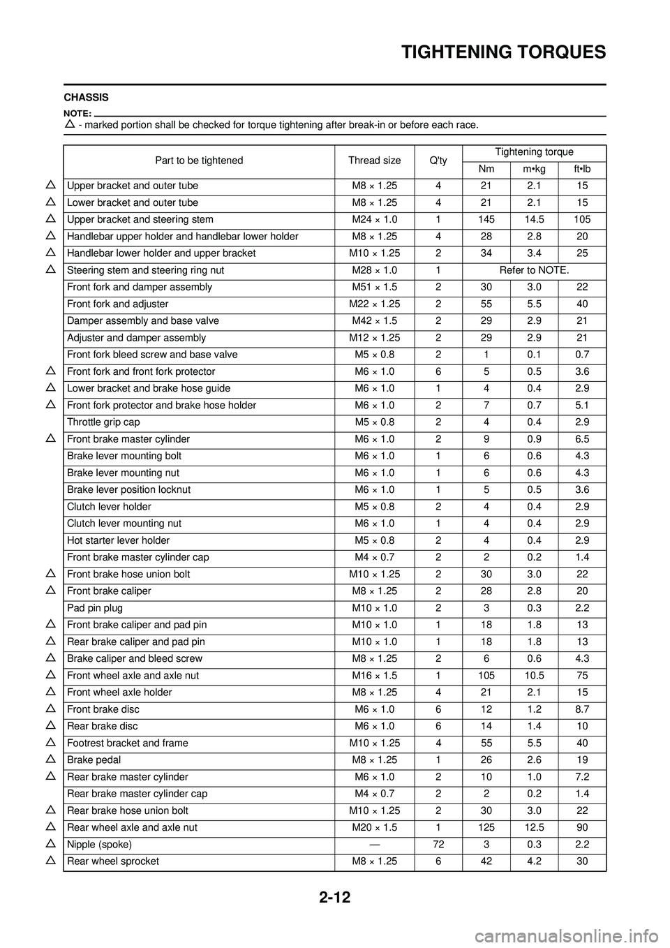
CHASSIS
△- marked portion shall be checked for torque tightening after break-in or before each race.
Part to be tightenedThread size Q'tyTightening torque
Nm m•kg ft•lb
△Upper bracket and outer tube M8 × 1.25 4 21 2.1 15
△Lower bracket and outer tube M8 × 1.25 4 21 2.1 15
△Upper bracket and steering stem M24 × 1.0 1 145 14.5 105
△Handlebar upper holder and handlebar lower holderM8 × 1.25 4 28 2.8 20
△Handlebar lower holder and upper bracketM10 × 1.25 2 34 3.4 25
△Steering stem and steering ring nut M28 × 1.0 1Refer to NOTE.
Front fork and damper assembly M51 × 1.5 2 30 3.0 22
Front fork and adjuster M22 × 1.25 2 55 5.5 40
Damper assembly and base valve M42 × 1.5 2 29 2.9 21
Adjuster and damper assembly M12 × 1.25 2 29 2.9 21
Front fork bleed screw and base valve M5 × 0.8 2 1 0.1 0.7
△Front fork and front fork protector M6 × 1.0 6 5 0.5 3.6
△Lower bracket and brake hose guideM6 × 1.0 1 4 0.4 2.9
△Front fork protector and brake hose holderM6 × 1.0 2 7 0.7 5.1
Throttle grip cap M5 × 0.8 2 4 0.4 2.9
△Front brake master cylinderM6 × 1.0 2 9 0.9 6.5
Brake lever mounting bolt M6 × 1.0 1 6 0.6 4.3
Brake lever mounting nut M6 × 1.0 1 6 0.6 4.3
Brake lever position locknut M6 × 1.0 1 5 0.5 3.6
Clutch lever holder M5 × 0.8 2 4 0.4 2.9
Clutch lever mounting nut M6 × 1.0 1 4 0.4 2.9
Hot starter lever holder M5 × 0.8 2 4 0.4 2.9
Front brake master cylinder cap M4 × 0.7 2 2 0.2 1.4
△Front brake hose union boltM10 × 1.25 2 30 3.0 22
△Front brake caliper M8 × 1.25 2 28 2.8 20
Pad pin plug M10 × 1.0 2 3 0.3 2.2
△Front brake caliper and pad pinM10 × 1.0 1 18 1.8 13
△Rear brake caliper and pad pin M10 × 1.0 1 18 1.8 13
△Brake caliper and bleed screwM8 × 1.25 2 6 0.6 4.3
△Front wheel axle and axle nut M16 × 1.5 1 105 10.5 75
△Front wheel axle holderM8 × 1.25 4 21 2.1 15
△Front brake disc M6 × 1.0 6 12 1.2 8.7
△Rear brake disc M6 × 1.0 6 14 1.4 10
△Footrest bracket and frameM10 × 1.25 4 55 5.5 40
△Brake pedal M8 × 1.25 1 26 2.6 19
△Rear brake master cylinder M6 × 1.0 2 10 1.0 7.2
Rear brake master cylinder cap M4 × 0.7 2 2 0.2 1.4
△Rear brake hose union boltM10 × 1.25 2 30 3.0 22
△Rear wheel axle and axle nut M20 × 1.5 1 125 12.5 90
△Nipple (spoke) —72 3 0.3 2.2
△Rear wheel sprocket M8 × 1.25 6 42 4.2 30
Page 36 of 192

2-14
TIGHTENING TORQUES
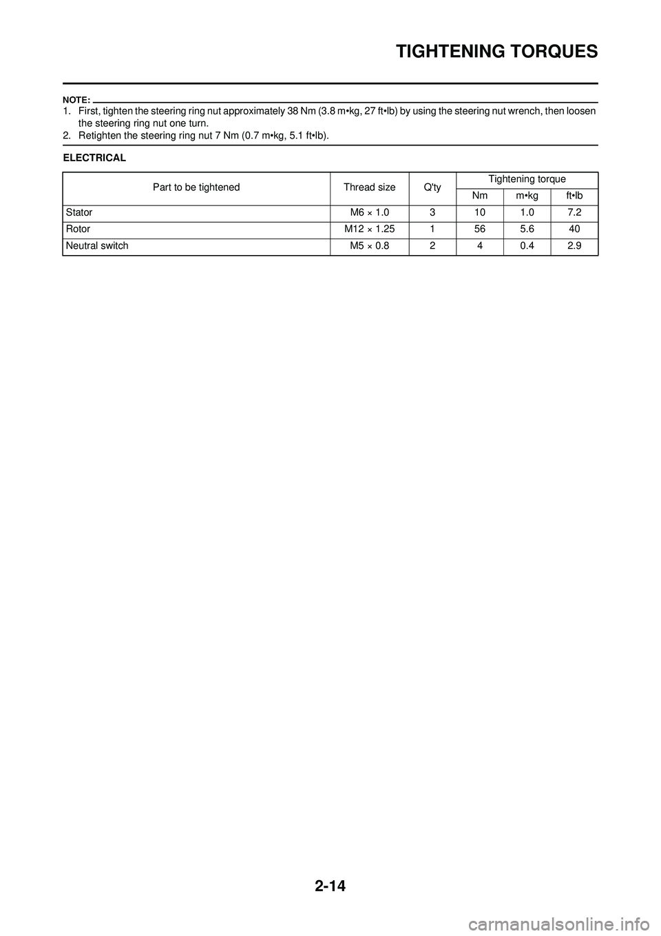
1. First, tighten the steering ring nut approximately 38 Nm (3.8 m•kg, 27 ft•lb) by using the steering nut wrench, then loosen the steering ring nut one turn.
2. Retighten the steering ring nut 7 Nm (0.7 m•kg, 5.1 ft•lb).
ELECTRICAL
Part to be tightened Thread size Q'ty Tightening torque
Nm m•kg ft•lb
Stator M6 × 1.0 3 10 1.0 7.2
Rotor M12 × 1.25 1 56 5.6 40
Neutral switch M5 × 0.8 2 4 0.4 2.9
Page 40 of 192

2-18
CABLE ROUTING DIAGRAM
CABLE ROUTING DIAGRAM
1. Fuel tank breather hose
2. Radiator hose 1
3. Connector cover
4. Cylinder head breather hose
5. Radiator hose 4
6. Clutch cable
7. Throttle position sensor lead
8. Carburetor breather hose
9. Upper engine bracket10. Hot starter cable
11. Fuel hose
12. Carburetor overflow hose
A. Insert the end of the fuel tank
breather hose into the hole in
the steering stem.
B. Install the connector cover so that it does not come in between
the radiator hose 1 and radiator. C. Aligh the paint mark on the cylin-
der head breather hose with the
front end of the hose guide.
D. Pass the cylinder head breather hose on the outside of the radia-
tor hose 1 and then between the
radiator 4 and frame.
E. Pass the clutch cable through
the cable guide.