Page 177 of 192
6-4
IGNITION SYSTEM
3. Inspect:• Charging coil 2 resistanceOut of specification
→Replace.
CHECKING THE NEUTRAL
SWITCH
1. Inspect: • Neutral switch conduction
Not conductive while it is in neutral
→
Replace.
Conductive while it is engaged
→Re-
place.
Set the tester selection position to
"
Ω × 1".
CHECKING THE CDI UNIT
Check all electrical components. If no
fault is found, replace the CDI unit.
Then check the electrical compo-
nents again. Tester (+) lead
→Pink lead "1"
Tester (-) lead
→Black lead "2"
Charging
coil 2 resis- tance Tester se-
lector posi- tion
44-66
Ω at
20 °C (68
°F)
Ω ×10
Tester (+) lead
→Sky blue lead
"1"
Tester (-) lead
→Ground "2"
Result Conductive (while gear
is in neutral)
Page 178 of 192
6-5
THROTTLE POSITION SENSOR SYSTEM
THROTTLE POSITION SENSOR SYSTEM
INSPECTION STEPS
If the throttle position sensor will not operate, use the following inspection steps.
*marked: Refer to "IGNITION SYSTEM" section.
Use the following special tools in this inspection.
Check entire ignition system for connection. No good→Repair or replace.
OK
↓
Check throttle position sensor. (Throttle position
sensor coil) No good→Replace.
OK
↓
*Check CDI magneto. (Charging coil) No good→Replace.
OK
↓
Check CDI unit. (Throttle position sensor input
voltage) No good→Replace.
Pocket tester:
YU-3112-C/90890-03112
Page 179 of 192
 \"1\" except when
changing the throttle position sen-
sor due to failure because it will
cause a d")
6-6
THROTTLE POSITION SENSOR SYSTEM
HANDLING NOTE
Do not loosen the screw (throttle
position sensor) "1" except when
changing the throttle position sen-
sor due to failure because it will
cause a drop in engine perfor-
mance.
CHECKING THE COUPLERS AND
LEADS CONNECTION
1. Check:• Couplers and leads connectionRust/dust/looseness/short-circuit
→Repair or replace.
CHECKING THE THROTTLE
POSITION SENSOR COIL
1. Inspect: • Throttle position sensor coil resis-
tance
Out of specification
→Replace.
2. Loosen: • Throttle stop screw "1"
Turn out the throttle stop screw until
the throttle shaft is in the full close po-
sition.
3. Inspect:• Throttle position sensor coil vari-able resistance
Check that the resistance in in-
creased as the throttle grip is
moved from the full close position
to the full open position.
Out of specification
→Replace.
CHANGING AND ADJUSTING THE
THROTTLE POSITION SENSOR
1. Remove: • Throttle position sensor coupler
•Carburetor
2. Remove:
• Screw (throttle position sensor) "1"
• Throttle position sensor "2"
Loosen the screw (throttle position
sensor) using the T25 bit.
3. Replace: • Throttle position sensor 4. Install:
• Throttle position sensor "1"
• Screw (throttle position sensor) "2"
• Align the slot "a" in the throttle posi-
tion sensor with the projection "b"
on the carburetor.
• Temporarily tighten the screw
(throttle position sensor).
5. Install:•Carburetor
• Throttle position sensor coupler
6. Adjust: • Engine idling speed
Refer to "ADJUSTING THE EN-
GINE IDLING SPEED" section in
the CHAPTER 3.
7. Insert the thin electric conductors "2" (lead) into the throttle position
sensor coupler "1", as shown, and
connect the tester to them.
�ŒDo not insert the electric conduc-
tors more than required because
it may reduce the waterproof
function of the coupler.
• Make sure that a short-circuit does not develop between the
terminals because it may cause
damage to electrical compo-
nents.
8. Start the engine.
9. Adjust:• Throttle position sensor output
voltage
Adjustment steps:
a. Adjust the installation angle of the throttle position sensor "1" to ob-
tain the specified output voltage.
Tester (+) lead
→Blue lead "1"
Tester (-) lead
→Black lead "2"
Throttle po- sition sen- sor coil
resistance Tester se-
lector posi- tion
4–6 k
Ω at
20°C (68 °F) kΩ×1
Tester (+) lead→Yellow lead "1"
Tester (-) lead
→Black lead "2"
Throttle position sensor coil vari-
able resistance Tester
selec-
tor po- sition
Full
closed Full
opened
k
Ω×1
Zero –3
kΩat
20°C
(68 °F) 4–6
kΩat
20 °C
(68 °F)
Tester (+) lead→Yellow lead "3"
Tester (-) lead
→Black lead "4"
Page 180 of 192
6-7
THROTTLE POSITION SENSOR SYSTEM
Measure the output voltage accurate-
ly with a digital electronic voltmeter
that gives an easy reading of a small
voltage.
10. Put the aligning marks "a" on the throttle position sensor and car-
buretor.
11. Stop the engine.
12. Remove the carburetor.
13. Tighten: • Screw (throttle position sensor) "1"
Tighten the screw (throttle position
sensor) using the T25 bit.
14. Install the carburetor.
CHECKING THE THROTTLE
POSITION SENSOR INPUT
VOLTAGE
1. Disconnect the throttle position
sensor coupler.
2. Start the engine.
3. Inspect:
• Throttle position sensor input volt-age
Out of specification
→Replace the CDI unit.
Throttle po- sition sen-
sor output voltage Tester se-
lector posi- tion
0.58–0.78 V DCV
Tester (+) lead→Blue lead "1"
Tester (-) lead
→Black/Blue lead
"2"
Throttle po-sition sen-
sor input voltage Tester se-
lector posi-
tion
4–6 V DCV-20
Page 181 of 192

7-1
ENGINE
TUNING
ENGINE
CARBURETOR SETTING
• The air/fuel mixture will vary de-pending on atmospheric conditions.
Therefore, it is necessary to take
into consideration the air pressure,
ambient temperature, humidity,
etc., when adjusting the carburetor.
• Perform a test run to check for prop- er engine performance (e.g., throt-
tle response) and spark plug(-s)
discoloration or fouling. Use these
readings to determine the best pos-
sible carburetor setting.
It is recommended to keep a record of
all carburetor settings and external
conditions (e.g., atmospheric condi-
tions, track/surface conditions, lap
times) to make future carburetor set-
ting easier.
• The carburetor is a part of the fuel line. Therefore, be sure to in-
stall it in a wellventilated area,
away from flammable objects
and any sources of fire.
• Never look into the carburetor in- take. Flames may shoot out from
the pipe if the engine backfires
while it is being started. Gasoline
may be discharged from the ac-
celerator pump nozzle when the
carburetor has been removed.
• The carburetor is extremely sen-sitive to foreign matter (dirt,
sand, water, etc.). During instal-
lation, do not allow foreign mat-
ter to get into the carburetor.
• Always handle the carburetor and its components carefully.
Even slight scratches, bends or
damage to carburetor parts may
prevent the carburetor from
functioning correctly. Carefully
perform all servicing with the ap-
propriate tools and without ap-
plying excessive force.
• When the engine is stopped or when riding at no load, do not
open and close the throttle un-
necessarily. Otherwise, too
much fuel may be discharged,
starting may become difficult or
the engine may not run well.
• After installing the carburetor,
check that the throttle operates correctly and opens and closes
smoothly.
ATMOSPHERIC CONDITIONS AND
CARBURETOR SETTINGS
The air density (i.e., concentration of
oxygen in the air) determines the rich-
ness or leanness of the air/fuel mix-
ture.
• Higher temperature expands the air
with its resultant reduced density.
• Higher humidity reduces the amount of oxygen in the air by so
much of the water vapor in the
same air.
• Lower atmospheric pressure (at a high altitude) reduces the density of
the air.
EFFECT OF SETTING PARTS IN
RELATION TO THROTTLE VALVE
OPENING
A. Closed
B. Fully open
1. Pilot screw/pilot jet
2. Throttle valve cutaway
3. Jet needle
4. Main jet CONSTRUCTION OF
CARBURETOR AND SETTING
PARTS
The FLATCR carburetor has a prima-
ry main jet. This type of main jet is
perfect for racing machines since it
supplies an even flow of fuel, even at
full load. Use the main jet and the jet
needle to set the carburetor.
The FLATCR carburetor is manufac-
tured with a pilot screw. The pilot
screw adjustment ranges from fully
closed throttle to 1/4 open throttle.
1. Jet needle
2. Pilot air jet
3. Needle jet
4. Main jet
5. Pilot jet
6. Pilot screw
ADJUSTING THE MAIN JET
The richness of the air-fuel mixture at
full throttle can be set by changing the
main jet "1".
If the air-fuel mixture is too rich or too
lean, the engine power will drop, re-
sulting in poor acceleration.
Effects of changing the main jet
(reference)
A. Idle
B. Fully open
1. #180
2. #175
3. #178
Air
tem p. Hu-
midi- ty Air
pres-
sure
(alti-
tude) Mix-
ture Set-
ting
High High Low
(high) Rich-
er Lean-
er
Low Low High
(low) Lean-
er Rich-
er
Standard main jet #178
7
Page 182 of 192

7-2
ENGINE
ADJUSTING THE PILOT SCREW
The richness of the air-fuel mixture
with the throttle fully closed to 1/4
open can be set by turning the pilot
screw "1". Turning in the pilot screw
will make the mixture lean at low
speeds, and turning it out will enrich
it.
• If the engine idling speed fluctuates, turn the pilot screw only 1/2 of a turn
in either direction.
• To optimize the fuel flow at a small- er throttle opening, each machine's
pilot screw has been individually set
at the factory. Before adjusting the
pilot screw, turn it in fully and count
the number of turns. Record this
number as the factory-set number
of turns out.
Effects of adjusting the pilot screw
(reference)
A. Idle
B. Fully open
1. 2-7/8 turns out
2. 1-7/8 turns out
3. 2-3/8 turns out
ADJUSTING THE PILOT JET
The richness of the air-fuel mixture
with the throttle open 1/4 or less can
be set by adjusting the pilot jet "1".
Effects of adjusting the pilot jet
(reference) A. Idle
B. Fully open
1. #45
2. #40
3. #42
ADJUSTING THE JET NEEDLE
GROOVE POSITION
Adjusting the jet needle "1" position
affects the acceleration when the
throttle is 1/8 to 3/4 open.
1. Too rich at intermediate speeds • Rough engine operation is felt
and the engine will not pick up
speed smoothly.
Step up the jet needle clip by one
groove and move down the nee-
dle to lean out the mixture.
2. Too lean at intermediate speeds
• The engine breathes hard and will not pick up speed quickly.
Step down the jet needle clip by
one groove and move up the nee-
dle to enrich the mixture.
Effects of changing the jet needle
groove position (reference) A. Idle
B. Fully open
1. No.6 groove
2. No.4 groove
3. No.5 groove
ADJUSTING THE JET NEEDLE
The jet needle is adjusted by chang-
ing it.
The jet needle setting parts, having
the same taper angle, are available in
different straight portion diameters
and in different taper starting posi-
tions. a. Diameter of the straight por- tion
b. Reference needle
c. 0.5 leaner
Changing from NFPR-5 to NFLR-5
has the same effect as a lowering of
0.5 clip position. Effects of changing the jet needle
(reference)
(Diameter of the straight portion)
Changing the diameter of the straight
portion adjusts the air-fuel mixture
when the throttle is 1/8 to 1/4 open.
A. Idle
B. Fully open
RELATIONSHIP WITH THROTTLE
OPENING
The flow of the fuel through the car-
buretor main system is controlled by
the main jet and then, it is further reg-
ulated by the area between the main
nozzle and the jet needle.
The fuel flow relates to the diameter
of the straight portion of the jet needle
with the throttle 1/8 to 1/4 open and
relates to the clip position with the
throttle 1/8 to 3/4 open.
Therefore, the fuel flow is balanced at
each stage of throttle opening by the
combination of the jet needle straight
portion diameter and clip position.
ADJUSTING THE LEAK JET
(ADJUSTING THE ACCELERATOR
PUMP)
The leak jet "1" is a setting part that
adjusts the flow of fuel discharged by
the accelerator pump. Since the ac-
celerator pump operates only when
throttle is open, the leak jet is used to
adjust a fuel mixture ratio for quick
throttle opening and is therefore dif-
ferent from other setting parts that ad-
just a fuel mixture for each throttle
opening (each engine speed).
1. When the engine breathes hard in quick throttle opening, select a
leak jet having lower calibrating
No. than standard to enrich the
mixture. #70
→#60
Standard pilot screw
position (example) 2-3/8
Standard pilot jet #42
Standard clip posi- tion No.5
groove
Standard jet needle NFPR
Page 183 of 192

7-3
ENGINE
2. When rough engine operation is felt in quick throttle opening, se-
lect a leak jet having higher cali-
brating No. than standard to lean
out the mixture. #70
→#80 CARBURETOR SETTING PARTS
Standard leak jet #70
Main jet Size Part number Rich #188 4MX-14943-95 #185 4MX-14943-44
#182 4MX-14943-94
#180 4MX-14943-43
(STD) #178 4MX-14943-93 #175 4MX-14943-42
#172 4MX-14943-92
#170 4MX-14943-41
Lean #168 4MX-14943-91
Pilot jet Size Part number Rich #48 4MX-14948-06 #45 4MX-14948-05
(STD) #42 4MX-14948-04 #40 4MX-14948-03
Lean #38 4MX-14948-02
Jet needle Size Part number Rich NFPN 5TA-14916-PN NFPP 5TA-14916-PP
NFPQ 5TA-14916-P1
(STD) NFPR 5TA-14916-PR NFPS 5TA-14916-PSNFPT 5TA-14916-PT
Lean NFPU 5TA-14916-PU Rich NFLN 5TA-14916-LN NFLP 5TA-14916-LP
NFLQ 5TA-14916-L1
NFLR 5TA-14916-LRNFLS 5TA-14916-LSNFLT 5TA-14916-LT
Lean NFLU 5TA-14916-LU
Leak jet Size Part number Rich #40 4JT-1494F-03 #50 4JT-1494F-07
#60 4JT-1494F-11
(STD) #70 4JT-1494F-15 #80 4JT-1494F-19
#90 4JT-1494F-23
Lean #100 4JT-1494F-27
Page 184 of 192

7-4
ENGINE
SPECIFICATIONS OF JET NEEDLE
EXAMPLES OF CARBURETOR SETTING DEPENDING ON SYMPTOMDiameter of straight portion
Rich Lean
NPQRS TU
Rich 1 richer NFPN-6 NFPP-6 NFPQ-6 NFPR-6 NFPS-6 NFPT-6 NFPU-6 0.5 richer NFLN-6 NFLP-6 NFLQ-6 NFLR-6 NFLS-6 NFLT-6 NFLU-6STD NFPN-5 NFPP-5 NFPQ-5 NFPR-5 NFPS-5 NFPT-5 NFPU-5
0.5 leaner NFLN-5 NFLP-5 NFLQ-5 NFLR-5 NFLS-5 NFLT-5 NFLU-5
Lean 1 leaner NFPN-4 NFPP-4 NFPQ-4 NFPR-4 NFPS-4 NFPT-4 NFPU-4
Symptom Setting Checking
At full throttle Hard breathing
Shearing noise
Whitish spark plug
↓
Lean mixture Increase main jet calibration no. (Gradual-
ly)
Discoloration of spark plug
→If tan color, it
is in good condition.
If cannot be corrected: Clogged float valve seat
Clogged fuel hose
Clogged fuel cock
Check that the accelerator pump operates
smoothly.
At full throttle Speed pick-up stops
Slow speed pick-up
Slow response
Sooty spark plug
↓
Rich mixture Decrease main jet calibration no. (Gradual-
ly)
Discoloration of spark plug
→If tan color, it
is in good condition.
If cannot be corrected:
Clogged air filter
Fuel overflow from carburetor
Lean mixture Lower jet needle clip position. (1 groove
down)
The clip position is the jet needle groove on
which the clip is installed.
The positions are numbered from the top.
Check that the accelerator pump operates
smoothly. (except for rich mixture symp-
tom).
Rich mixture
Raise jet needle clip position. (1 groove up)
1/4–3/4 throttle Hard breathing
Lack of speed Lower jet needle clip position. (1 groove
down)
1/4–1/2 throttle Slow speed pick-up
Poor acceleration Raise jet needle clip position. (1 groove up)
Closed to 1/4 throttle Hard breathing
Speed down Use jet needle with a smaller diameter. Slow-speed-circuit passage
Clogged
→Clean.
Overflow from carburetor
Closed to 1/4 throttle Poor acceleration Use jet needle with a larger diameter.
Raise jet needle clip position. (1 groove up)
Poor response in the low to in-
termediate speeds Raise jet needle clip position.
If this has no effect, lower the jet needle clip
position.
Poor response when throttle is
opened quickly Check overall settings.
Use main jet with a lower calibration no.
Raise jet needle clip position. (1 groove up)
If these have no effect, use a main jet with
a higher calibration no. and lower the jet
needle clip position. Check air filter for fouling.
Check that the accelerator pump operates
smoothly.
Jet needleClip
Groove 7 Groove 6
Groove 5
Groove 4
Groove 3
Groove 2
Groove 1
Leaner
(Standard) Richer
 1
1 2
2 3
3 4
4 5
5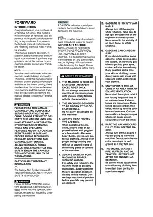 6
6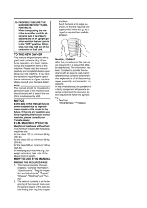 7
7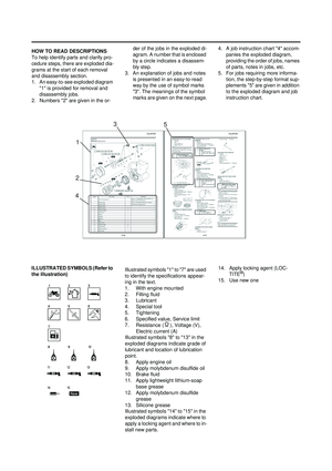 8
8 9
9 10
10 11
11 12
12 13
13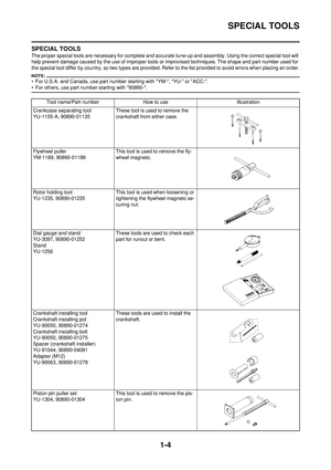 14
14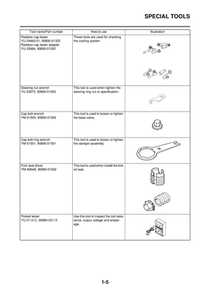 15
15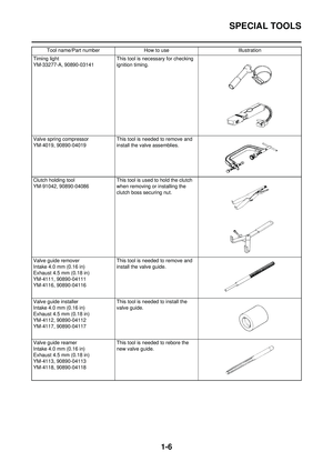 16
16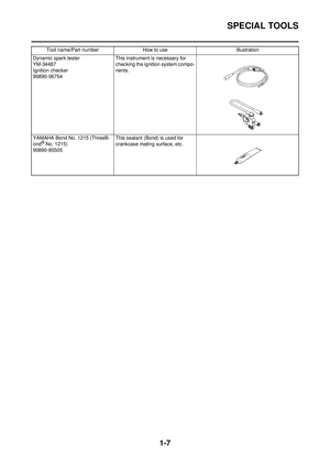 17
17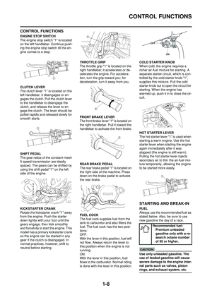 18
18 19
19 20
20 21
21 22
22 23
23 24
24 25
25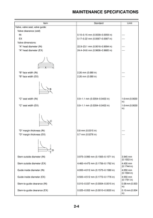 26
26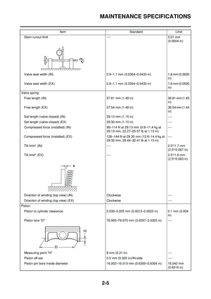 27
27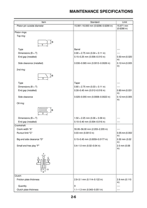 28
28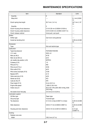 29
29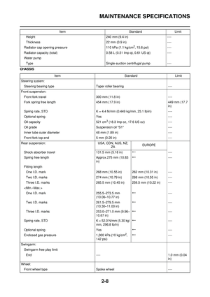 30
30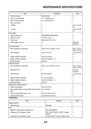 31
31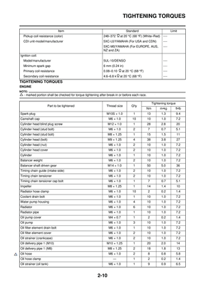 32
32 33
33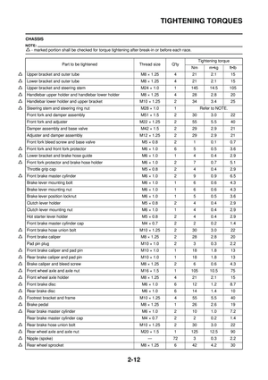 34
34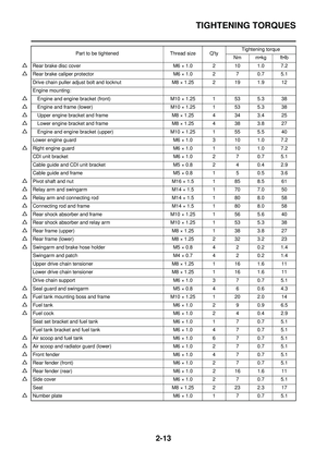 35
35 36
36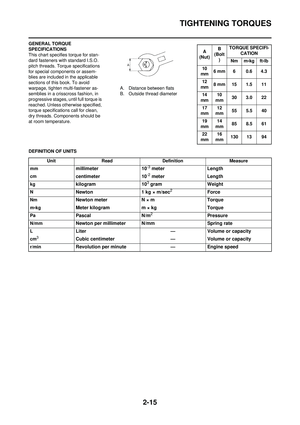 37
37 38
38 39
39 40
40 41
41 42
42 43
43 44
44 45
45 46
46 47
47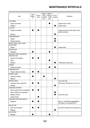 48
48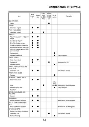 49
49 50
50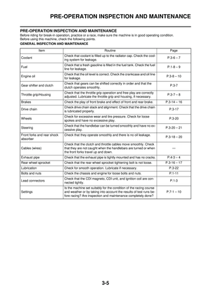 51
51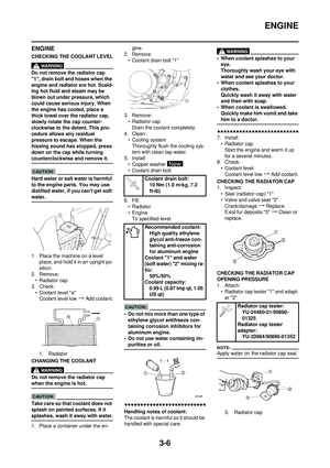 52
52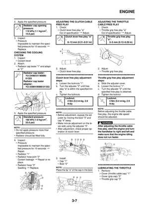 53
53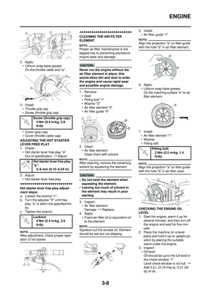 54
54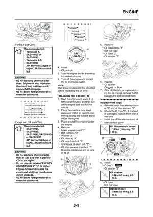 55
55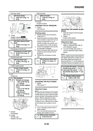 56
56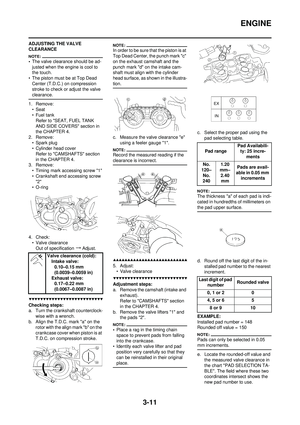 57
57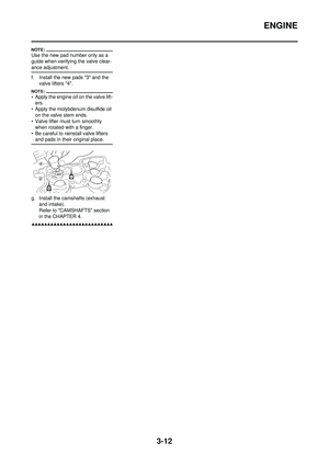 58
58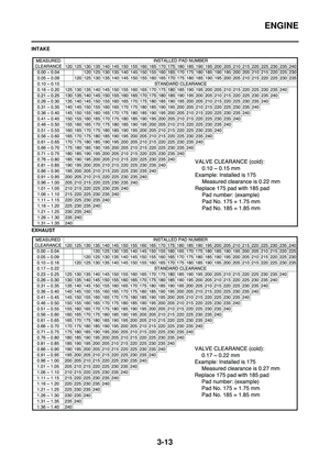 59
59 60
60 61
61 62
62 63
63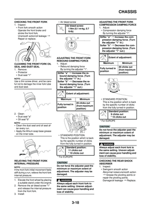 64
64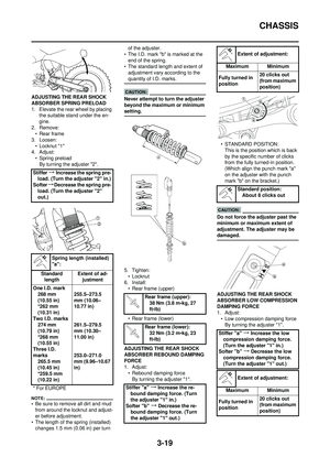 65
65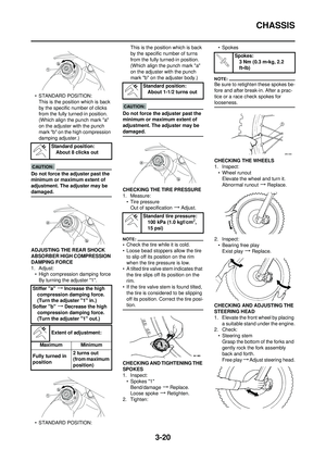 66
66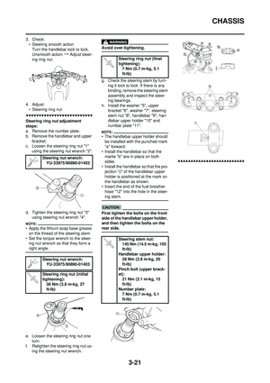 67
67 68
68 69
69 70
70 71
71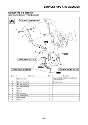 72
72 73
73 74
74 75
75 76
76 77
77 78
78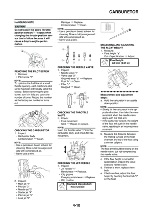 79
79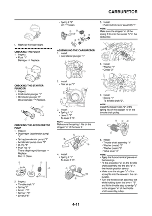 80
80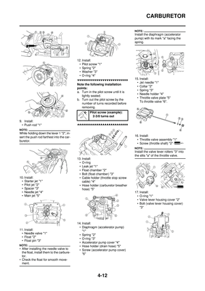 81
81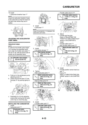 82
82 83
83 84
84 85
85 86
86 87
87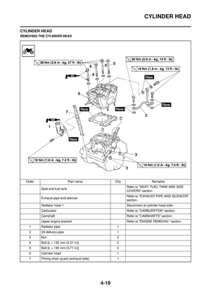 88
88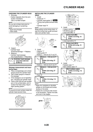 89
89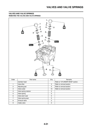 90
90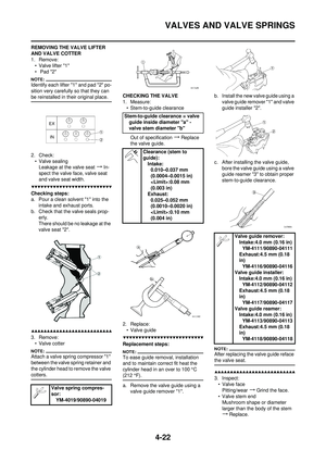 91
91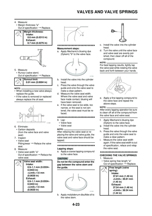 92
92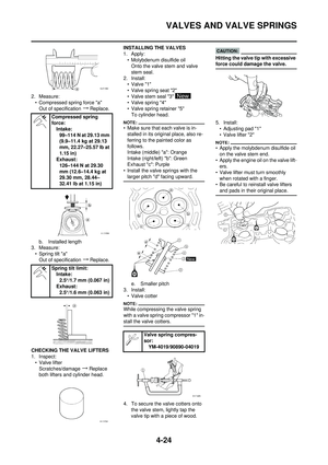 93
93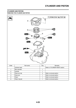 94
94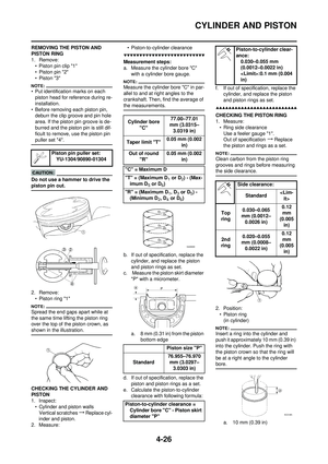 95
95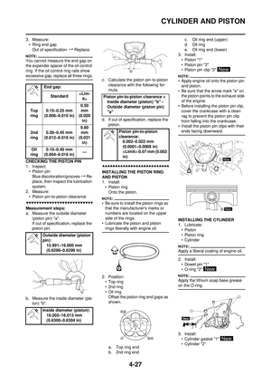 96
96 97
97 98
98 99
99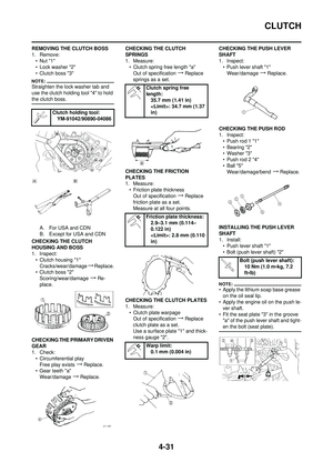 100
100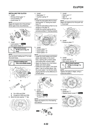 101
101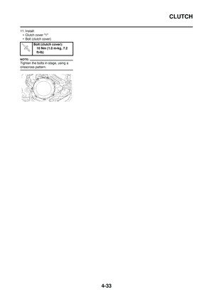 102
102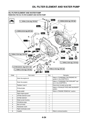 103
103 104
104 105
105 106
106 107
107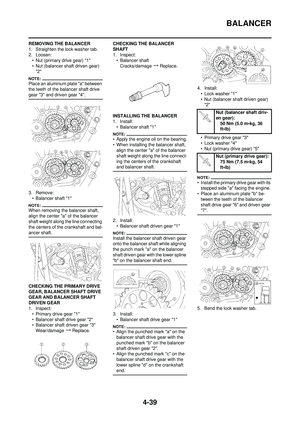 108
108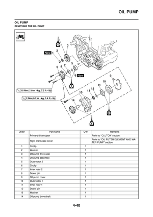 109
109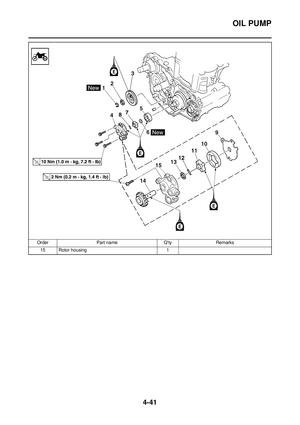 110
110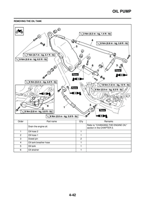 111
111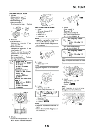 112
112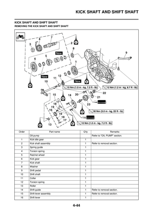 113
113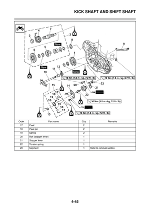 114
114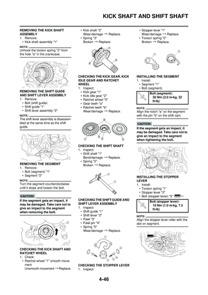 115
115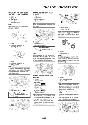 116
116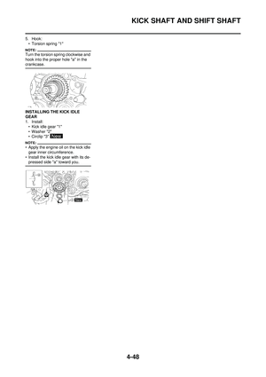 117
117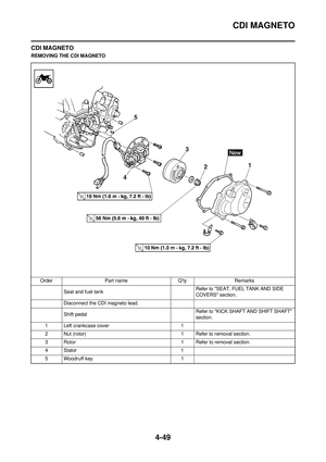 118
118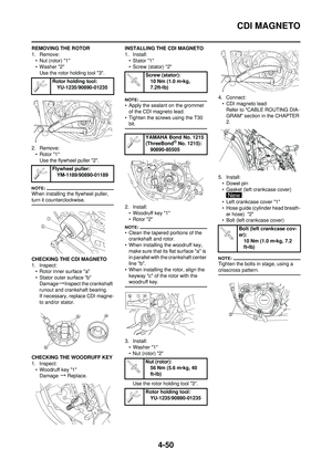 119
119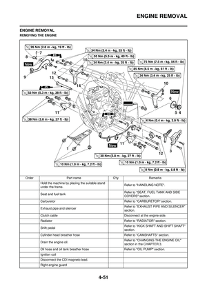 120
120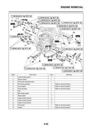 121
121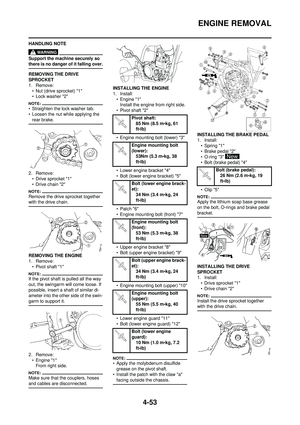 122
122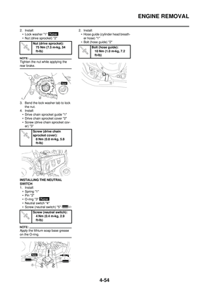 123
123 124
124 125
125 126
126 127
127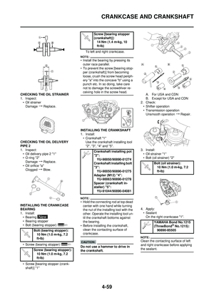 128
128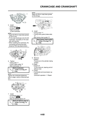 129
129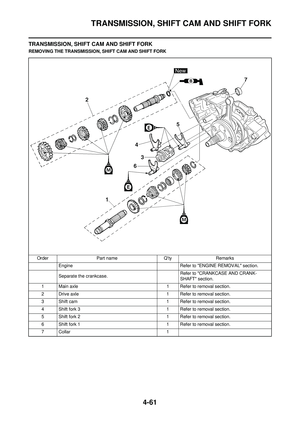 130
130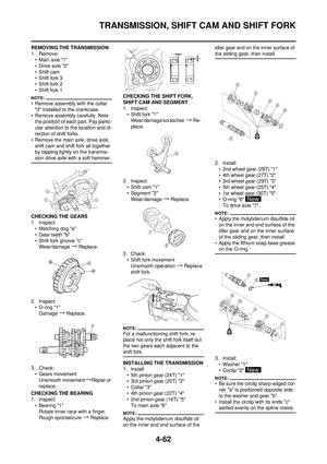 131
131 132
132 133
133 134
134 135
135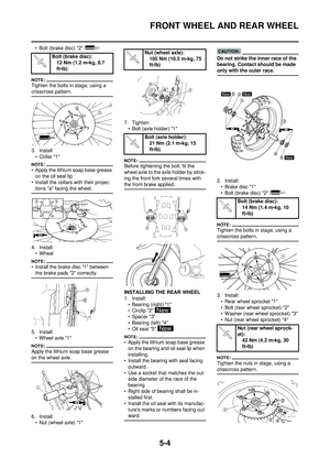 136
136 137
137 138
138 139
139 140
140 141
141 142
142 143
143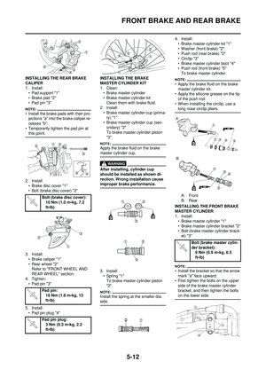 144
144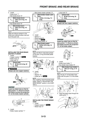 145
145 146
146 147
147 148
148 149
149 150
150 151
151 152
152 153
153 154
154 155
155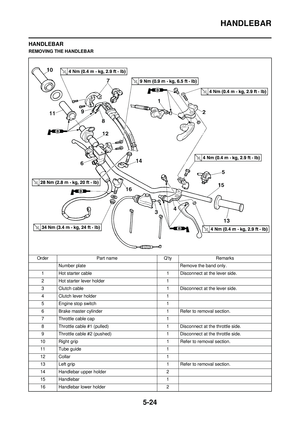 156
156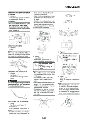 157
157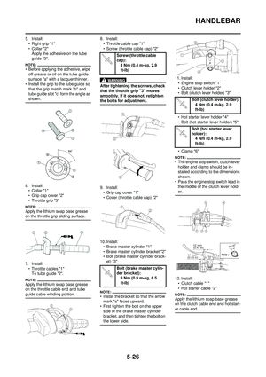 158
158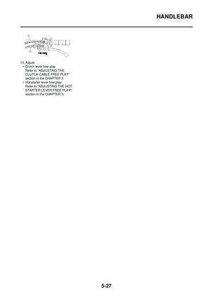 159
159 160
160 161
161 162
162 163
163 164
164 165
165 166
166 167
167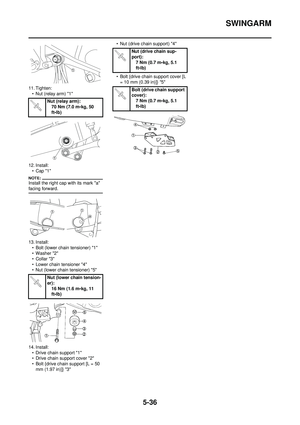 168
168 169
169 170
170 171
171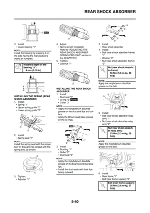 172
172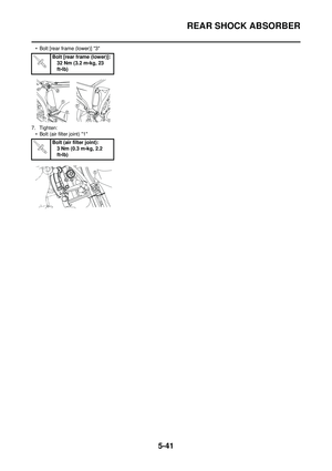 173
173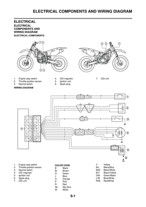 174
174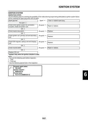 175
175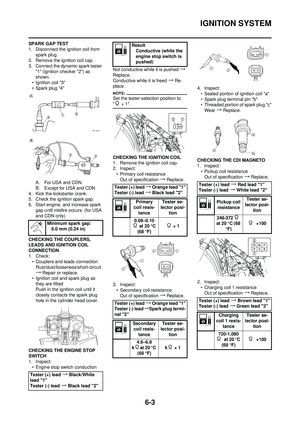 176
176 177
177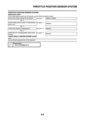 178
178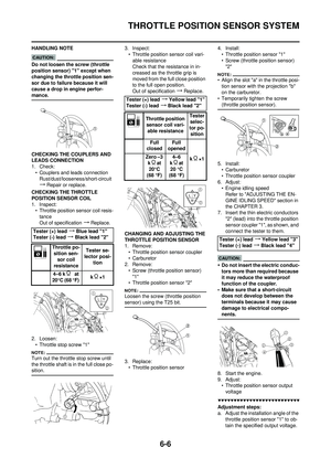 179
179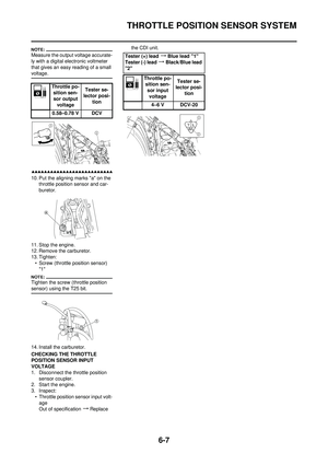 180
180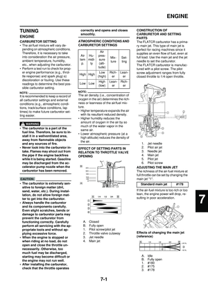 181
181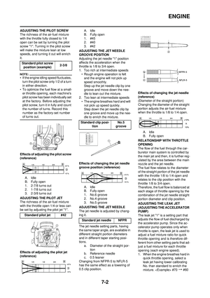 182
182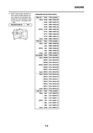 183
183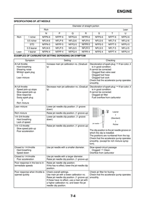 184
184 185
185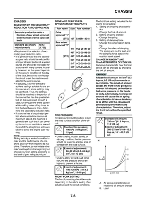 186
186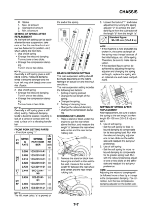 187
187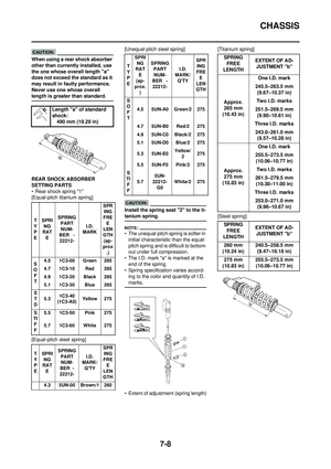 188
188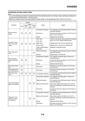 189
189 190
190 191
191

