Page 185 of 192
7-5
ENGINE
* This should be taken simply for an example. It is necessary to set the carburetor while checking the operating conditions
of the engine.
Page 186 of 192

<Requirement for selection of sec-
ondary gear reduction ratio>
• It is generally said that the second-ary gear ratio shoul")
7-6
CHASSIS
CHASSIS
SELECTION OF THE SECONDARY
REDUCTION RATIO (SPROCKET)
ondary gear reduction ratio>
• It is generally said that the second-ary gear ratio should be reduced for
a longer straight portion of a speed
course and should be increased for
a course with many corners. Actual-
ly, however, as the speed depends
on the ground condition of the day
of the race, be sure to run through
the circuit to set the machine suit-
able for the entire course.
• In actuality, it is very difficult to achieve settings suitable for the en-
tire course and some settings may
be sacrificed. Thus, the settings
should be matched to the portion of
the course that has the greatest ef-
fect on the race result. In such a
case, run through the entire course
while making notes of lap times to
find the best balance; then, deter-
mine the secondary reduction ratio.
• If a course has a long straight por-
tion where a machine can run at
maximum speed, the machine is
generally set such that it can devel-
op its maximum revolutions toward
the end of the straight line, with care
taken to avoid the engine over-rev-
ving.
Riding technique varies from rider to
rider and the performance of a ma-
chine also vary from machine to ma-
chine. Therefore, do not imitate other
rider's settings from the beginning but
choose your own setting according to
the level of your riding technique.
DRIVE AND REAR WHEEL
SPROCKETS SETTING PARTS
TIRE PRESSURE
Tire pressure should be adjust to suit
the road surface condition of the cir-
cuit.
• Under a rainy, muddy, sandy, or slippery condition, the tire pressure
should be lower for a larger area of
contact with the road surface.
• Under a stony or hard road condi- tion, the tire pressure should be
higher to prevent a flat tire.
FRONT FORK SETTING
The front fork setting should be made
depending on the rider's feeling of an
actual run and the circuit conditions. The front fork setting includes the fol-
lowing three factors:
1. Setting of air spring characteris-
tics
• Change the fork oil amount.
2. Setting of spring preload • Change the spring.
3. Setting of damping force • Change the compression damp-ing.
• Change the rebound damping. The spring acts on the load and
the damping force acts on the
cushion travel speed.
CHANGE IN AMOUNT AND
CHARACTERISTICS OF FORK OIL
Damping characteristic near the final
stroke can be changed by changing
the fork oil amount.
Adjust the oil amount in 5 cm3 (0.2
Imp oz, 0.2 US oz) increments or
decrements. Too small oil amount
causes the front fork to produce a
noise at full rebound or the rider to
feel some pressure on his hands
or body. Alternatively, too large oil
amount will cause the air spring
characteristics to have a tendency
to be stiffer with the consequent
deteriorated performance and
characteristics. Therefore, adjust
the front fork within the specified
range.
A. Air spring characteristics in relation to oil amount change
B. Load
Secondary reduction ratio =
Number of rear wheel sprocket
teeth/Number of drive sprocket
teeth
Standard secondary
reduction ratio 49/13
(3.769)
Part name Size Part number
Drive
sprocket "1" (STD) 13T 9383B-13218
Rear wheel
sprocket "2" 47T 1C3-25447-00
48T 1C3-25448-00
(STD) 49T 1C3-25449-00 50T 1C3-25450-00
51T 1C3-25451-00
52T 1C3-25452-00
Standard tire pressure: 100 kPa (1.0 kgf/cm
2,
15 psi)
Extent of adjustment: 60–80 kPa (0.6–0.8 kgf/
cm
2, 9.0–12 psi)
Extent of adjustment: 100–120 kPa (1.0–1.2
kgf/cm
2, 15–18 psi)
Standard oil amount:330 cm3 (11.6 Imp oz,
11.2 US oz)
Extent of adjustment: 300–375 cm
3(10.6–13.2
Imp oz, 10.1–12.7 US
oz)
Page 187 of 192

7-7
CHASSIS
C. Stroke
1. Max. oil amount
2. Standard oil amount
3. Min. oil amount
SETTING OF SPRING AFTER
REPLACEMENT
As the front fork setting can be easily
affected by rear suspension, take
care so that the machine front and
rear are balanced (in position, etc.)
when setting the front fork.
1. Use of soft spring • Change the rebound damping.Turn out one or two clicks.
• Change the compression damp-
ing.
Turn in one or two clicks.
Generally a soft spring gives a soft
riding feeling. Rebound damping
tends to become stronger and the
front fork may sink deeply over a se-
ries of gaps.
2. Use of stiff spring• Change the rebound damping.Turn in one or two clicks.
• Change the compression damp-
ing.
Turn out one or two clicks.
Generally a stiff spring gives a stiff
riding feeling. Rebound damping
tends to become weaker, resulting in
lack of a sense of contact with the
road surface or in a vibrating handle-
bar.
FRONT FORK SETTING PARTS
• Front fork spring "1"
The I.D. mark (slits) "a" is proved on the end of the spring.
REAR SUSPENSION SETTING
The rear suspension setting should
be made depending on the rider's
feeling of an actual run and the circuit
conditions.
The rear suspension setting includes
the following two factors:
1. Setting of spring preload
• Change the set length of the spring.
• Change the spring.
2. Setting of damping force • Change the rebound damping.
• Change the compression damp-ing.
CHOOSING SET LENGTH
1. Place a stand or block under the engine to put the rear wheel
above the floor, and measure the
length "a" between the rear wheel
axle center and the rear fender
holding bolt.
2. Remove the stand or block from the engine and with a rider astride
the seat, measure the sunken
length "b" between the rear wheel
axle center and the rear fender
holding bolt. 3. Loosen the locknut "1" and make
adjustment by turning the spring
adjuster "2" to achieve the stan-
dard figure from the subtraction of
the length "b" from the length "a".
• If the machine is new and after it is broken in, the same set length of
the spring may change because of
the initial fatigue, etc. of the spring.
Therefore, be sure to make reeval-
uation.
• If the standard figure cannot be achieved by adjusting the spring
adjuster and changing the spring
set length, replace the spring with
an optional one and make readjust-
ment.
SETTING OF SPRING AFTER
REPLACEMENT
After replacement, be sure to adjust
the spring to the set length [sunken
length 90–100 mm (3.5–3.9 in)] and
set it.
1. Use of soft spring• Set the soft spring for less re-bound damping to compensate
for its less spring load. Run with
the rebound damping adjuster
one or two clicks on the softer
side and readjust it to suit your
preference.
2. Use of stiff spring
• Set the soft spring for more re-bound damping to compensate
for its greater spring load. Run
with the rebound damping adjust-
er one or two clicks on the stiffer
side and readjust it to suit your
preference.
Adjusting the rebound damping will
be followed more or less by a change
in the compression damping. For cor-
rection, turn the low compression
damping adjuster on the softer side.
TY
PE SPRIN
G
RATE SPRING
PART NUM- BER I.D.
MA
RK
(slit
s)
SO FT 0.398 1C3-23141-A1 |
0.408 1C3-23141-B1 ||
0.418 1C3-23141-C1 |||
0.428 1C3-23141-D1 ||||
0.438 1C3-23141-E1 |||||
ST D 0.449 5XC-23141-
N0—
STI FF 0.459 1C3-23141-
G1|-||
0.469 1C3-23141-H1 |-|||
0.479 1C3-23141-J1 |-||||
Standard figure: 90–100 mm (3.5–3.9 in)
Page 188 of 192

7-8
CHASSIS
When using a rear shock absorber
other than currently installed, use
the one whose overall length "a"
does not exceed the standard as it
may result in faulty performance.
Never use one whose overall
length is greater than standard.
REAR SHOCK ABSORBER
SETTING PARTS
• Rear shock spring "1"
[Equal-pitch titanium spring]
[Equal-pitch steel spring][Unequal-pitch steel spring]
Install the spring seat "2" to the ti-
tanium spring.
• The unequal-pitch spring is softer in
initial characteristic than the equal-
pitch spring and is difficult to bottom
out under full compression.
• The I.D. mark "a" is marked at the end of the spring.
• Spring specification varies accord-
ing to the color and quantity of I.D.
marks.
• Extent of adjustment (spring length) [Titanium spring]
[Steel spring]
Length "a" of standard
shock:
490 mm (19.29 in)
T
Y
P
E SPRI
NG
RAT
E SPRING
PART
NUM-
BER -
22212- I.D.
MARK SPR
ING
FRE E
LEN
GTH
(ap-
prox
.)
S
O F
T 4.5 1C3-00 Green 265
4.7 1C3-10 Red 265
4.9 1C3-20 Black 265
5.1 1C3-30 Blue 265
S T
D 5.3
1C3-40
(1C3-A0) Yellow 275
S
TI
F
F 5.5 1C3-50 Pink 275
5.7 1C3-60 White 275
T
Y
P
E SPRI
NG
RAT
E SPRING
PART NUM-
BER -
22212- I.D.
MARK/
Q'TY SPR
ING
FRE E
LEN
GTH
4.3 5UN-00 Brown/1 260
T
Y
P
E SPRI
NG
RAT
E
(ap-
prox. ) SPRING
PART
NUM-
BER -
22212- I.D.
MARK/ Q'TY SPR
ING
FRE E
LEN
GTH
S
O
F
T 4.5 5UN-A0 Green/2 275
4.75UN-B0Red/2275
4.9 5UN-C0 Black/2 275
5.1 5UN-D0 Blue/2 275
5.3 5UN-E0
Yellow/
2 275
5.5 5UN-F0 Pink/2 275
S
TI F
F 5.7
5UN-
22212- G0 White/2 275
SPRING
FREE
LENGTH EXTENT OF AD-
JUSTMENT "b"
Approx. 265 mm
(10.43 in) One I.D. mark
245.5–263.5 mm (9.67–10.37 in)
Two I.D. marks
251.5–269.5 mm (9.90–10.61 in)
Three I.D. marks 243.0–261.0 mm (9.57–10.28 in)
Approx. 275 mm
(10.83 in) One I.D. mark
255.5–273.5 mm (10.06–10.77 in)
Two I.D. marks
261.5–279.5 mm (10.30–11.00 in)
Three I.D. marks 253.0–271.0 mm (9.96–10.67 in)
SPRING FREE
LENGTH EXTENT OF AD-
JUSTMENT "b"
260 mm
(10.24 in) 240.5–258.5 mm
(9.47–10.18 in)
275 mm
(10.83 in) 255.5–273.5 mm
(10.06–10.77 in)
Page 189 of 192

• If any of the following symptoms is experienced with the standard position as the base, make resetting by reference to the adjustment procedure given in")
7-9
CHASSIS
SUSPENSION SETTING (FRONT FORK)
• If any of the following symptoms is experienced with the standard position as the base, make resetting by reference to the adjustment procedure given in the same chart.
• Before any change, set the rear shock absorber sunken length to the standard figure 90–100 mm (3.5–3.9 in).
Symptom Section
Check Adjust
Jump Large
gap Medi-
um
gap Small
gap
Stiff over entire
range
○○○
Compression damping Turn adjuster counterclockwise (about 2 clicks) to decrease damping.
Oil amount Decrease oil amount by about 5–10 cm
3 (0.2–0.4
Imp oz, 0.2–0.3 US oz).
Spring Replace with soft spring.
Unsmooth move-
ment over entire
range
○○○○
Outer tube Check for any bends, dents, and other noticeable
scars, etc. If any, replace affected parts.
Inner tube
Slide metal Replace with a new one for extended use.
Piston metal Replace with a new one for extended use.
Under bracket tighten-
ing torque Retighten to specified torque.
Poor initial move-
ment
○
Rebound damping Turn adjuster counterclockwise (about 2 clicks) to decrease damping.
Oil seal Apply grease in oil seal wall.
Soft over entire
range, bottoming
out
○○
Compression damping Turn adjuster clockwise (about 2 clicks) to in- crease damping.
Oil amount Increase oil amount by about 5–10 cm
3 (0.2–0.4
Imp oz, 0.2–0.3 US oz).
Spring Replace with stiff spring.
Stiff toward stroke
end
○Oil amount Decrease oil amount by about 5 cm3 (0.2 Imp
oz,0.2 US oz).
Soft toward stroke
end, bottoming out
○Oil amount Increase oil amount by about 5 cm3 (0.2 Imp
oz,0.2 US oz).
Stiff initial move-
ment
○○○○Compression damping Turn adjuster counterclockwise (about 2 clicks) to
decrease damping.
Low front, tending to
lower front posture
○○
Compression damping Turn adjuster clockwise (about 2 clicks) to in- crease damping.
Rebound damping Turn adjuster counterclockwise (about 2 clicks) to decrease damping.
Balance with rear end Set sunken length for 95–100 mm (3.7–3.9 in) when one passenger is astride seat (lower rear
posture).
Oil amount Increase oil amount by about 5 cm
3 (0.2 Imp oz,
0.2 US oz).
"Obtrusive" front,
tending to upper
front posture
○○
Compression damping Turn adjuster counterclockwise (about 2 clicks) to decrease damping.
Balance with rear end Set sunken length for 90–95 mm (3.5–3.7 in) when one passenger is astride seat (upper rear
posture).
Spring Replace with soft spring.
Oil amount Decrease oil amount by about 5–10 cm
3 (0.2–0.4
Imp oz, 0.2–0.3 US oz).
Page 190 of 192

• If any of the following symptoms is experienced with the standard position as the base, make resetting by reference to the adjustment procedur")
7-10
CHASSIS
SUSPENSION SETTING (REAR SHOCK ABSORBER)
• If any of the following symptoms is experienced with the standard position as the base, make resetting by reference to the adjustment procedure given in the same chart.
• Adjust the rebound damping in 2-click increments or decrements.
• Adjust the low compression damping in 1-click increments or decrements.
• Adjust the high compression damping in 1/6 turn increments or decrements.
Symptom Section
Check Adjust
Jump Large
gap Medi-
um
gap Small
gap
Stiff, tending to sink
○○
Rebound damping Turn adjuster counterclockwise (about 2 clicks) to decrease damping.
Spring set length Set sunken length for 90–100 mm (3.5–3.9 in) when one passenger is astride seat.
Spongy and unsta-
ble
○○
Rebound damping Turn adjuster clockwise (about 2 clicks) to in- crease damping.
Low compression
damping Turn adjuster clockwise (about 1 click) to increase
damping.
Spring Replace with stiff spring.
Heavy and dragging
○○
Rebound damping Turn adjuster counterclockwise (about 2 clicks) to decrease damping.
Spring Replace with soft spring.
Poor road gripping
○
Rebound damping Turn adjuster counterclockwise (about 2 clicks) to decrease damping.
Low compression
damping Turn adjuster clockwise (about 1 clicks) to in-
crease damping.
High compression
damping Turn adjuster clockwise (about 1/6 turn) to in-
crease damping.
Spring set length Set sunken length for 90–100 mm (3.5–3.9 in) when one passenger is astride seat.
Spring Replace with soft spring.
Bottoming out
○○
High compression
damping Turn adjuster clockwise (about 1/6 turn) to in-
crease damping.
Spring set length Set sunken length for 90–100 mm (3.5–3.9 in) when one passenger is astride seat.
Spring Replace with stiff spring.
Bouncing
○○
Rebound damping Turn adjuster clockwise (about 2 clicks) to in- crease damping.
Spring Replace with soft spring.
Stiff travel
○○
High compression
damping Turn adjuster counterclockwise (about 1/6 turn) to
decrease damping.
Spring set length Set sunken length for 90–100 mm (3.5–3.9 in) when one passenger is astride seat.
Spring Replace with soft spring.
Page 191 of 192
Page 192 of 192
PRINTED\bIN\bJAPAN(E\f
PRINTED\bON\bRECYCLED\b\OPAPER\bYAMAHA\bMOTOR\bCO.,\bLTD.
2500\b SHINGAI\b IWATA\b SHIZUOKA\b JAPAN
 1
1 2
2 3
3 4
4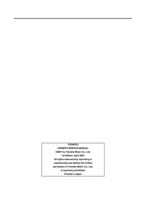 5
5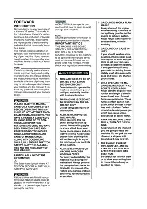 6
6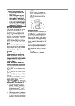 7
7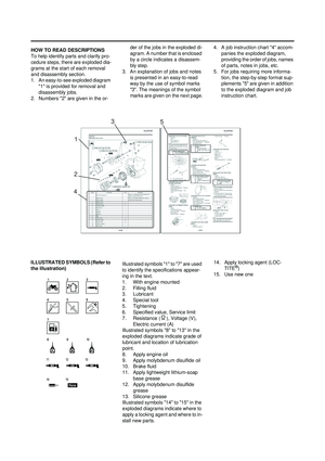 8
8 9
9 10
10 11
11 12
12 13
13 14
14 15
15 16
16 17
17 18
18 19
19 20
20 21
21 22
22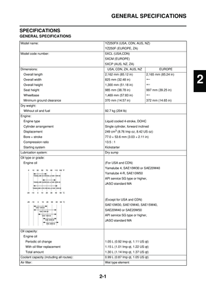 23
23 24
24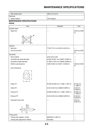 25
25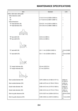 26
26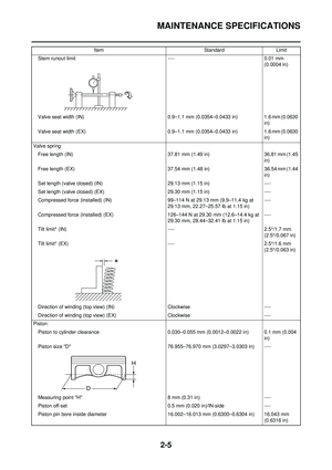 27
27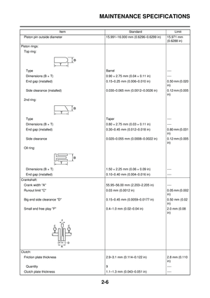 28
28 29
29 30
30 31
31 32
32 33
33 34
34 35
35 36
36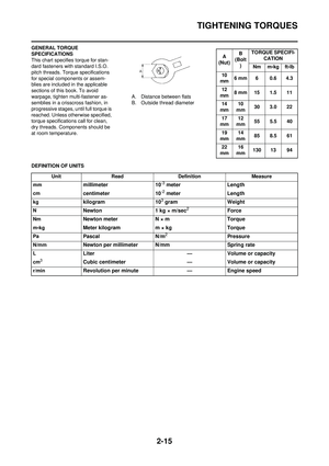 37
37 38
38 39
39 40
40 41
41 42
42 43
43 44
44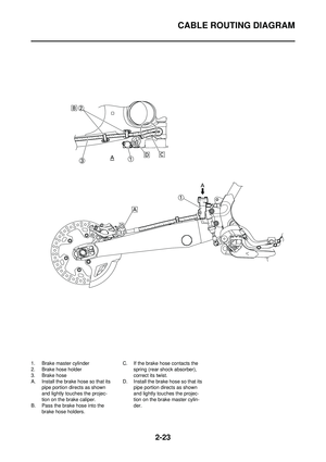 45
45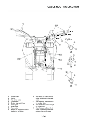 46
46 47
47 48
48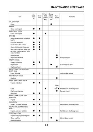 49
49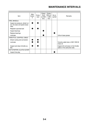 50
50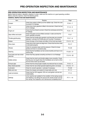 51
51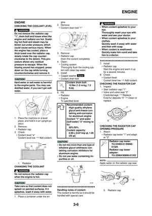 52
52 53
53 54
54 55
55 56
56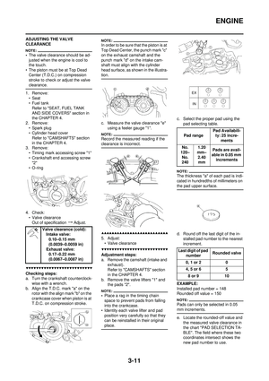 57
57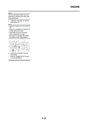 58
58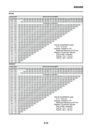 59
59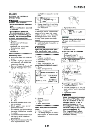 60
60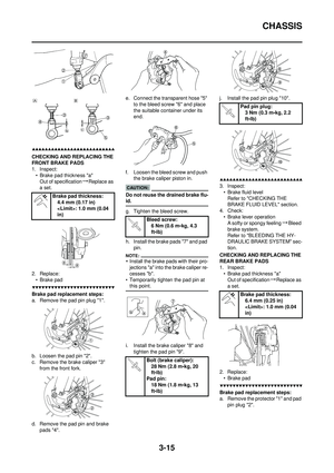 61
61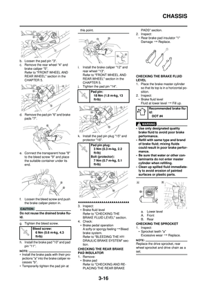 62
62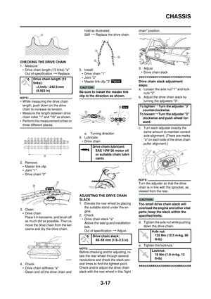 63
63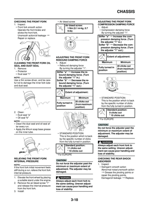 64
64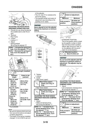 65
65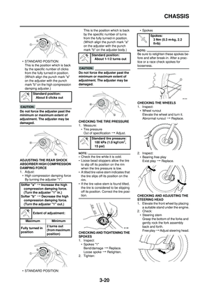 66
66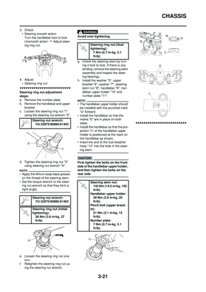 67
67 68
68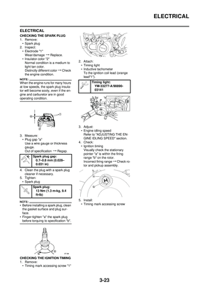 69
69 70
70 71
71 72
72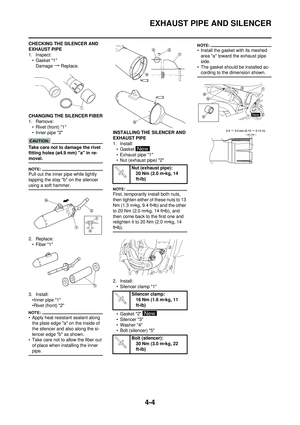 73
73 74
74 75
75 76
76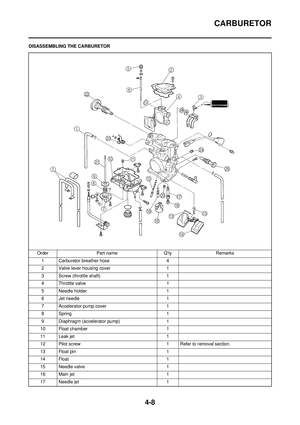 77
77 78
78 79
79 80
80 81
81 82
82 83
83 84
84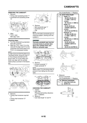 85
85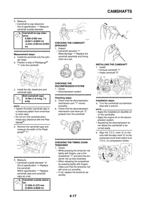 86
86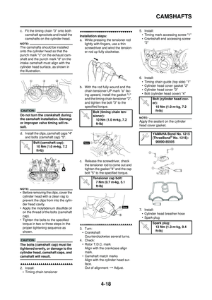 87
87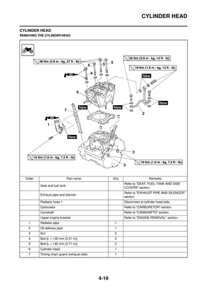 88
88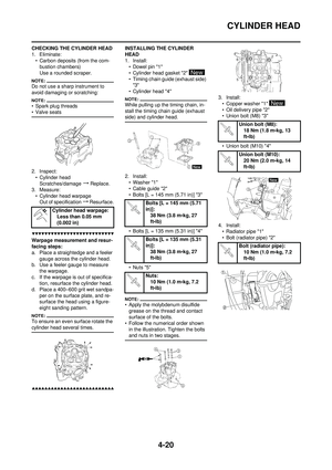 89
89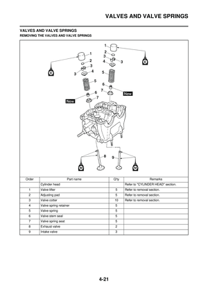 90
90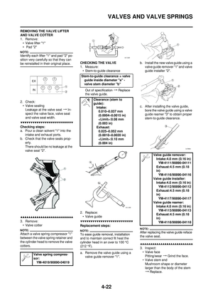 91
91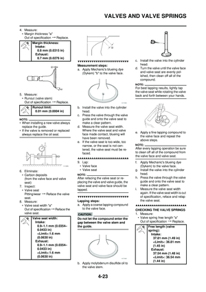 92
92 93
93 94
94 95
95 96
96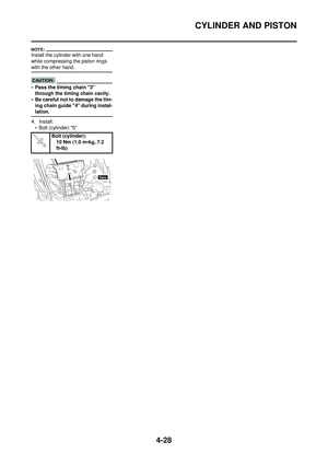 97
97 98
98 99
99 100
100 101
101 102
102 103
103 104
104 105
105 106
106 107
107 108
108 109
109 110
110 111
111 112
112 113
113 114
114 115
115 116
116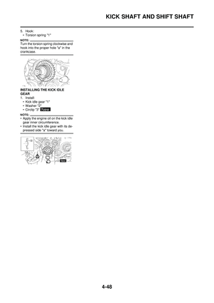 117
117 118
118 119
119 120
120 121
121 122
122 123
123 124
124 125
125 126
126 127
127 128
128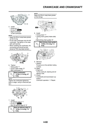 129
129 130
130 131
131 132
132 133
133 134
134 135
135 136
136 137
137 138
138 139
139 140
140 141
141 142
142 143
143 144
144 145
145 146
146 147
147 148
148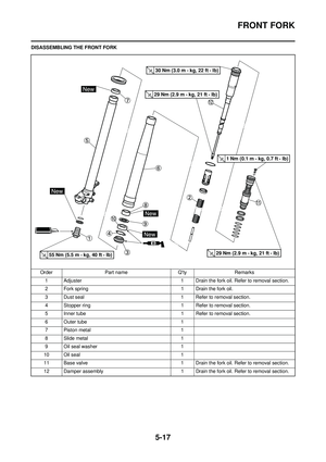 149
149 150
150 151
151 152
152 153
153 154
154 155
155 156
156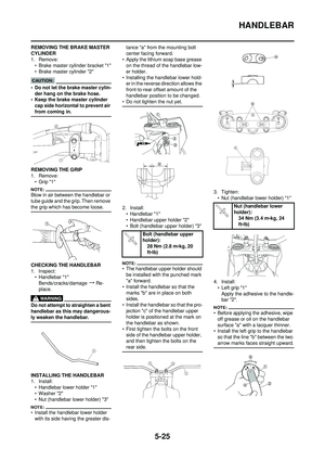 157
157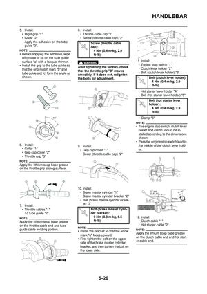 158
158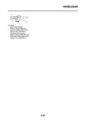 159
159 160
160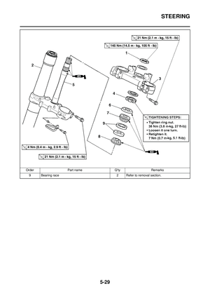 161
161 162
162 163
163 164
164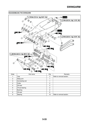 165
165 166
166 167
167 168
168 169
169 170
170 171
171 172
172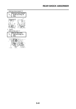 173
173 174
174 175
175 176
176 177
177 178
178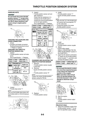 179
179 180
180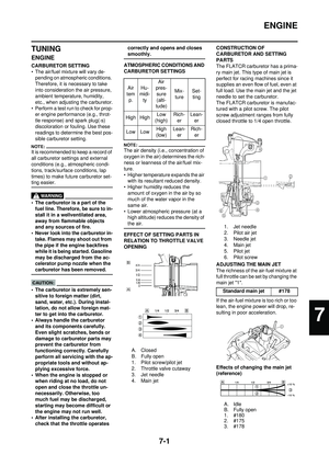 181
181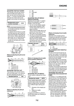 182
182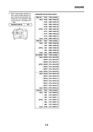 183
183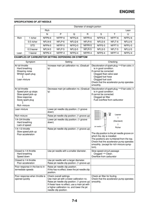 184
184 185
185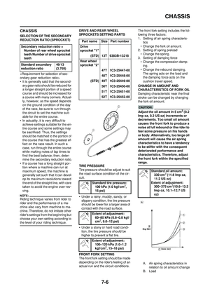 186
186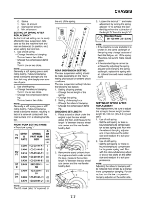 187
187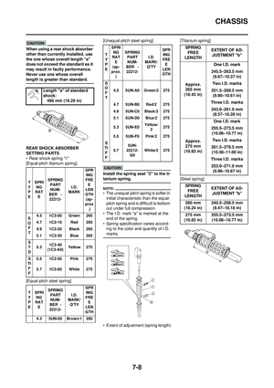 188
188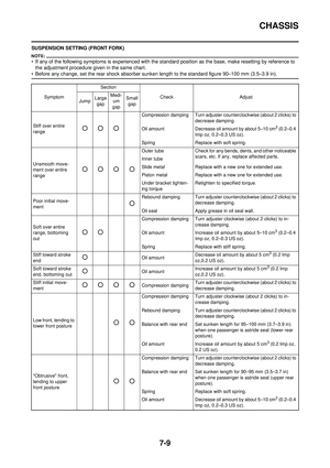 189
189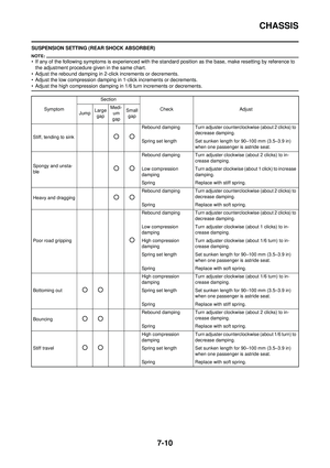 190
190 191
191

