2008 SUZUKI SX4 lock
[x] Cancel search: lockPage 71 of 278
3-6
STEERING COLUMN CONTROLS
80J21-03E
Turn Signal OperationWith the ignition switch in the “ON” posi-
tion, move the lever up or down to activate
the right or left turn signals.
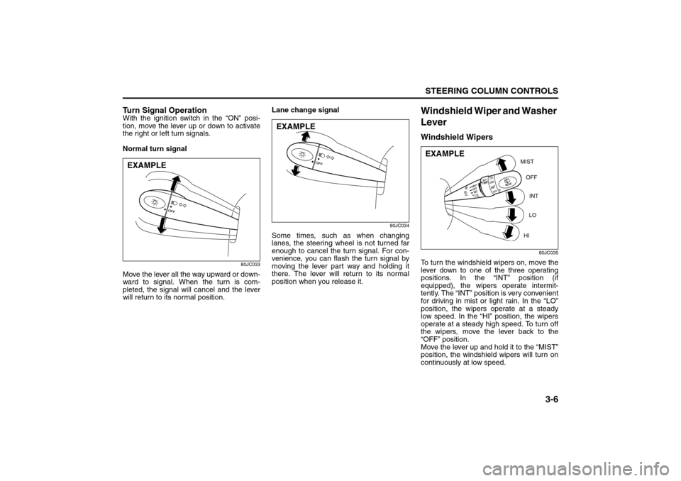
Normal turn signal
80JC033
Move the lever all the way upward or down-
ward to signal. When the turn is com-
pleted, the signal will cancel and the lever
will return to its normal position.Lane change signal
80JC034
Some times, such as when changing
lanes, the steering wheel is not turned far
enough to cancel the turn signal. For con-
venience, you can flash the turn signal by
moving the lever part way and holding it
there. The lever will return to its normal
position when you release it.
Windshield Wiper and Washer
LeverWindshield Wipers
80JC035
To turn the windshield wipers on, move the
lever down to one of the three operating
positions. In the “INT” position (if
equipped), the wipers operate intermit-
tently. The “INT” position is very convenient
for driving in mist or light rain. In the “LO”
position, the wipers operate at a steady
low speed. In the “HI” position, the wipers
operate at a steady high speed. To turn off
the wipers, move the lever back to the
“OFF” position.
Move the lever up and hold it to the “MIST”
position, the windshield wipers will turn on
continuously at low speed.
EXAMPLE
EXAMPLE
MIST
OFF
INT
LO
HI
EXAMPLE
Rear Window Wiper/Washer Switch: 8
Tilt Steering Lock Lever: 6
Cruise Control: 7, 8
Page 73 of 278
3-8
STEERING COLUMN CONTROLS
80J21-03E
Rear Window Wiper/Washer
Switch (if equipped)
80JC038
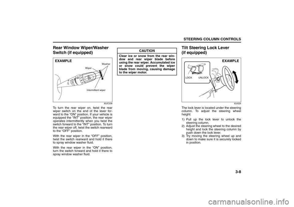
To turn the rear wiper on, twist the rear
wiper switch on the end of the lever for-
ward to the “ON” position. If your vehicle is
equipped the “INT” position, the rear wiper
operates intermittently when you twist the
switch forward to the “INT” position. To turn
the rear wiper off, twist the switch rearward
to the “OFF” position.
With the rear wiper in the “OFF” position,
twist the switch rearward and hold it there
to spray window washer fluid.
With the rear wiper in the “ON” position,
turn the switch forward and hold it there to
spray window washer fluid.
Tilt Steering Lock Lever
(if equipped)
63J026
The lock lever is located under the steering
column. To adjust the steering wheel
height:
1) Pull up the lock lever to unlock the
steering column.
2) Adjust the steering wheel to the desired
height and lock the steering column by
push down the lock lever.
3) Try moving the steering wheel up and
down to make sure it is securely locked
in position.
EXAMPLE
Intermittent wiper
Washer
Wiper
CAUTION
Clear ice or snow from the rear win-
dow and rear wiper blade before
using the rear wiper. Accumulated ice
or snow could prevent the wiper
blade from moving, causing damage
to the wiper motor.
LOCK UNLOCK
EXAMPLE
Cruise Control: 7, 8
Remote Audio Controls:
Horn: 6
Page 81 of 278
4-4
INSTRUMENT PANEL
80J21-03E
Refer to “Tire Pressure Monitoring System”
in the “OPERATING YOUR VEHICLE” sec-
tion for additional details on the tire pres-
sure monitoring system. Refer to “Tires” in
the “INSPECTION AND MAINTENANCE”
section for information on maintaining
proper tire pressure.
Brake System Warning Light
65D477
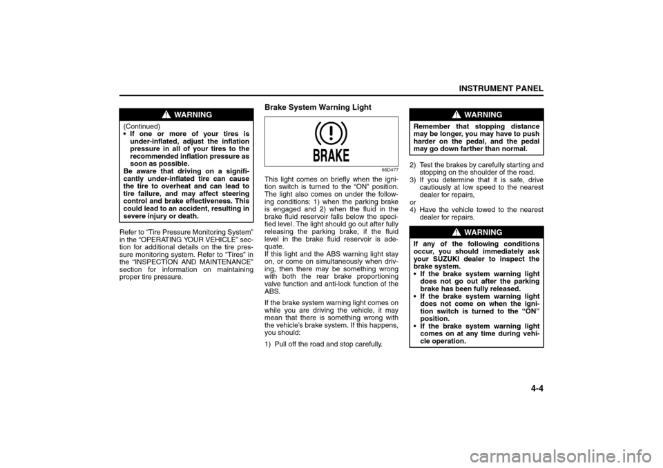
This light comes on briefly when the igni-
tion switch is turned to the “ON” position.
The light also comes on under the follow-
ing conditions: 1) when the parking brake
is engaged and 2) when the fluid in the
brake fluid reservoir falls below the speci-
fied level. The light should go out after fully
releasing the parking brake, if the fluid
level in the brake fluid reservoir is ade-
quate.
If this light and the ABS warning light stay
on, or come on simultaneously when driv-
ing, then there may be something wrong
with both the rear brake proportioning
valve function and anti-lock function of the
ABS.
If the brake system warning light comes on
while you are driving the vehicle, it may
mean that there is something wrong with
the vehicle’s brake system. If this happens,
you should:
1) Pull off the road and stop carefully.2) Test the brakes by carefully starting and
stopping on the shoulder of the road.
3) If you determine that it is safe, drive
cautiously at low speed to the nearest
dealer for repairs,
or
4) Have the vehicle towed to the nearest
dealer for repairs.
WARNING
(Continued)
If one or more of your tires is
under-inflated, adjust the inflation
pressure in all of your tires to the
recommended inflation pressure as
soon as possible.
Be aware that driving on a signifi-
cantly under-inflated tire can cause
the tire to overheat and can lead to
tire failure, and may affect steering
control and brake effectiveness. This
could lead to an accident, resulting in
severe injury or death.
WARNING
Remember that stopping distance
may be longer, you may have to push
harder on the pedal, and the pedal
may go down farther than normal.
WARNING
If any of the following conditions
occur, you should immediately ask
your SUZUKI dealer to inspect the
brake system.
If the brake system warning light
does not go out after the parking
brake has been fully released.
If the brake system warning light
does not come on when the igni-
tion switch is turned to the “ON”
position.
If the brake system warning light
comes on at any time during vehi-
cle operation.
Warning and Indicator Lights: 8
Page 82 of 278
4-5INSTRUMENT PANEL
80J21-03E
NOTE:
Because the disc brake system is self-
adjusting, the fluid level will drop as the
brake pads become worn.
Replenishing the brake fluid reservoir is
considered normal periodic maintenance.Anti-Lock Brake System (ABS)
Warning Light
65D529
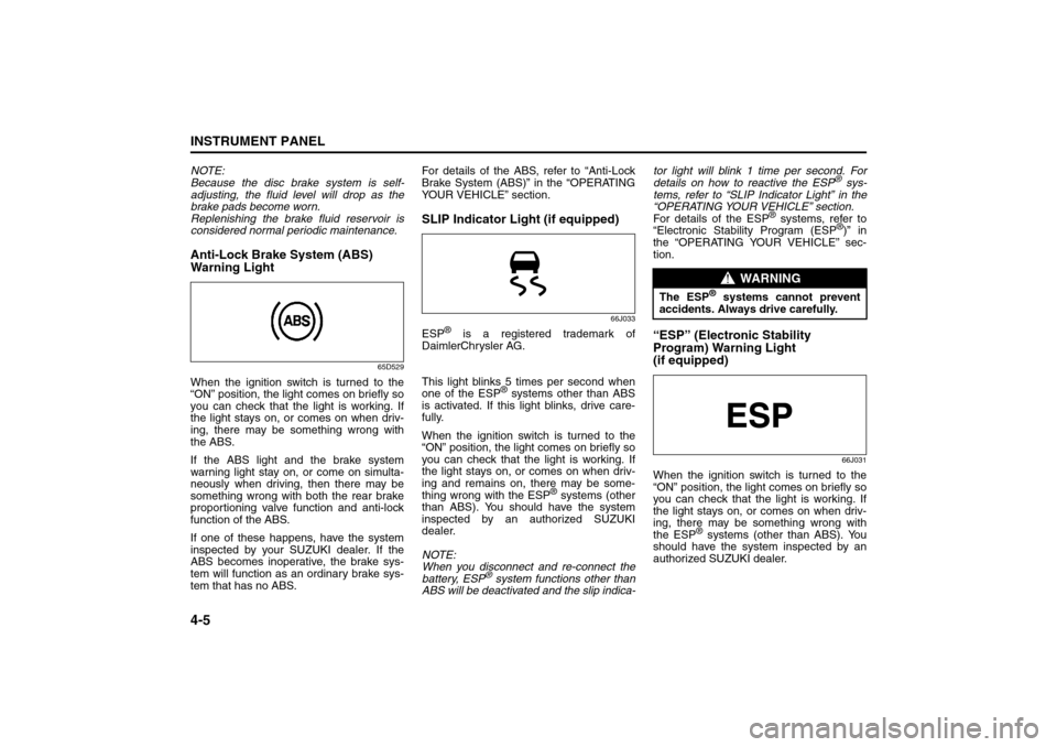
When the ignition switch is turned to the
“ON” position, the light comes on briefly so
you can check that the light is working. If
the light stays on, or comes on when driv-
ing, there may be something wrong with
the ABS.
If the ABS light and the brake system
warning light stay on, or come on simulta-
neously when driving, then there may be
something wrong with both the rear brake
proportioning valve function and anti-lock
function of the ABS.
If one of these happens, have the system
inspected by your SUZUKI dealer. If the
ABS becomes inoperative, the brake sys-
tem will function as an ordinary brake sys-
tem that has no ABS.For details of the ABS, refer to “Anti-Lock
Brake System (ABS)” in the “OPERATING
YOUR VEHICLE” section.
SLIP Indicator Light (if equipped)
66J033
ESP
® is a registered trademark of
DaimlerChrysler AG.
This light blinks 5 times per second when
one of the ESP
® systems other than ABS
is activated. If this light blinks, drive care-
fully.
When the ignition switch is turned to the
“ON” position, the light comes on briefly so
you can check that the light is working. If
the light stays on, or comes on when driv-
ing and remains on, there may be some-
thing wrong with the ESP
® systems (other
than ABS). You should have the system
inspected by an authorized SUZUKI
dealer.
NOTE:
When you disconnect and re-connect the
battery, ESP
® system functions other than
ABS will be deactivated and the slip indica-tor light will blink 1 time per second. For
details on how to reactive the ESP
® sys-
tems, refer to “SLIP Indicator Light” in the
“OPERATING YOUR VEHICLE” section.
For details of the ESP
® systems, refer to
“Electronic Stability Program (ESP
®)” in
the “OPERATING YOUR VEHICLE” sec-
tion.
“ESP” (Electronic Stability
Program) Warning Light
(if equipped)
66J031
When the ignition switch is turned to the
“ON” position, the light comes on briefly so
you can check that the light is working. If
the light stays on, or comes on when driv-
ing, there may be something wrong with
the ESP
® systems (other than ABS). You
should have the system inspected by an
authorized SUZUKI dealer.
WARNING
The ESP
® systems cannot prevent
accidents. Always drive carefully.
Warning and Indicator Lights: 8
Page 86 of 278
4-9INSTRUMENT PANEL
80J21-03E
If this light blinks in red, it reminds you that
the remote controller is not in the vehicle.
For details, refer to “Keyless Start System
Remote Controller/Keyless Entry System
Transmitter” in the “BEFORE DRIVING”
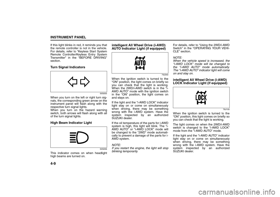
section.Turn Signal Indicators
50G055
When you turn on the left or right turn sig-
nals, the corresponding green arrow on the
instrument panel will flash along with the
respective turn signal lights.
When you turn on the hazard warning
switch, both arrows will flash along with all
of the turn signal lights.High Beam Indicator Light
50G056
This indicator comes on when headlight
high beams are turned on.
intelligent All Wheel Drive (i-AWD)
AUTO Indicator Light (if equipped)
79J040
When the ignition switch is turned to the
“ON” position, the light comes on briefly so
you can check that the light is working.
When the 2WD/i-AWD switch is in the “i-
AWD AUTO” mode with the ignition switch
in the “ON” position, the light comes on
and stays on.
If the light and the “i-AWD LOCK” indicator
light stay on or come on simultaneously
when driving, there may be something
wrong with the i-AWD system. Have the
system inspected by an authorized
SUZUKI dealer.
If the oil temperature of the parts for i-AWD
system is high, this light will blink. The “i-
AWD AUTO” or “i-AWD LOCK” mode will
be changed to the “2WD” mode automati-
cally to prevent a damage of the parts for i-
AWD system.
NOTE:
If you restart the engine, the light will stop
blinking temporarily.For details, refer to “Using the 2WD/i-AWD
Switch” in the “OPERATING YOUR VEHI-
CLE” section.
NOTE:
When the vehicle speed is increased, the
“i-AWD LOCK” mode will be changed to
the “i-AWD AUTO” mode automatically.
The “i-AWD AUTO” indicator light will come
on and stay on.
intelligent All Wheel Drive (i-AWD)
LOCK Indicator Light (if equipped)
79J100
When the ignition switch is turned to the
“ON” position, this light comes on briefly so
you can check that the light is working.
The light comes on when the 2WD/i-AWD
switch is changed to the “i-AWD LOCK”
mode from the “i-AWD AUTO” mode.
If the light and the “i-AWD AUTO” indicator
light stay on or come on simultaneously
when driving, there may be something
wrong with the i-AWD system. Have the
system inspected by an authorized
SUZUKI dealer.
Tachometer:
Fuel Gauge:
Page 87 of 278
4-10
INSTRUMENT PANEL
80J21-03E
NOTE:
When the vehicle speed is increased,
the “i-AWD LOCK” mode will be changed
to the “i-AWD AUTO” mode automati-
cally. The “i-AWD AUTO” indicator light
will come on and stay on.
When the ignition switch is turned to the
“OFF” position, the “i-AWD LOCK” mode
is canceled.
For details of the “i-AWD LOCK” mode,
refer to “Using the 2WD/i-AWD Switch” in
the “OPERATING YOUR VEHICLE” sec-
tion.
Daytime Running Light (D.R.L.) Indi-
cator Light (if equipped)
60B245
With the D.R.L. system, the headlights
light, but are dimmer than the low beam,
when the following three conditions are all
met. Whenever the D.R.L. system is oper-
ating, the D.R.L. indicator light remains on.
Conditions for D.R.L. system operation
1) The engine is running.
2) The parking brake is released.
3) The lighting switch is at either the “OFF”
or the “middle” position.
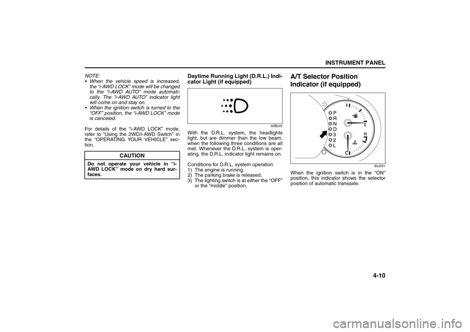
A/T Selector Position
Indicator (if equipped)
80J031
When the ignition switch is in the “ON”
position, this indicator shows the selector
position of automatic transaxle.
CAUTION
Do not operate your vehicle in “i-
AWD LOCK” mode on dry hard sur-
faces.
Temperature Gauge: 8
Hazard Warning Switch: 8
Rear Window Defroster Switch:
Page 94 of 278
4-17INSTRUMENT PANEL
80J21-03E
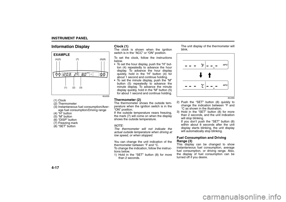
Information Display
80J035
(1) Clock
(2) Thermometer
(3) Instantaneous fuel consumption/Aver-
age fuel consumption/Driving range
(4) “H” button
(5) “M” button
(6) “DISP” button
(7) Freezing mark
(8) “SET” button
Clock (1)The clock is shown when the ignition
switch is in the “ACC” or “ON” position.
To set the clock, follow the instructions
below.
To set the hour display, push the “H” but-
ton (4) repeatedly to advance the hour
display. To advance the hour display
quickly, hold in the “H” button (4) for
about 1 second and continue holding.
To set the minute display, push the “M”
button (5) repeatedly to advance the
minute display. To advance the minute
display quickly, hold in the “M” button (5)
for about 1 second and continue holding.Thermometer (2)The thermometer shows the outside tem-
perature when the ignition switch is in the
“ON” position.
If the outside temperature nears freezing,
the mark (7) will come on when the display
shows the outside temperature.
NOTE:
The thermometer will not indicate the
actual outside temperature when driving at
low speed, or when stopped.
You can change the unit indication of the
thermometer between °F and °C.
To change the indication, follow the instruc-
tions below.
1) Hold in the “SET” button (8) for more
than 2 seconds.The unit display of the thermometer will
blink.
80J089
2) Push the “SET” button (8) quickly to
change the indication between °F and
°C as shown in the illustration.
3) Hold in the “SET” button (8) for more
than 2 seconds, and the unit indication
will stop blinking.
If you don’t push the “SET” button (8)
within about 8 seconds after the unit
display starts blinking, the unit display
will automatically stop blinking.Fuel Consumption and Driving
Range (3)This display can be changed to show
instantaneous fuel consumption, average
fuel consumption, or driving range. Also,
the display of fuel consumption can be
turned off if you desire.
(4)
(2)
(1)
(3)
(5)
(8)
(7)
(6)
EXAMPLE
Heating and Air Conditioning System: 4
Page 113 of 278

4-36
INSTRUMENT PANEL
80J21-03E
Turning power on/off
Press the power on/off knob (1).
The unit starts in the function mode it was
in when the power was turned off last.
Adjusting the volume
Turn the volume control knob (1).
Turning it clockwise increases the volume;
turning it counterclockwise decreases the
volume.
NOTE:
While driving, adjust the volume to an
extent that sound and/or noise coming
from outside the car can be heard.Adjusting bass/treble/balance/fader
1) Press the tone/balance/fader control
knob (2).
Each time it is pressed, sound adjust-
ment is changed as follows:
66J224
2) Turn the tone/balance/fader control
knob (2) to adjust the sound.Adjusting the AVC (Auto volume con-
trol)
The Automatic Volume Control (AVC) func-
tion automatically adjusts (increases/
decreases) the sound volume in accor-
dance with vehicle speed. The AVC control
is provided with three selectable levels
(LEVEL OFF, 1, 2, 3). The range of volume
adjustment increases together with the
LEVEL number,
1) Press the tone/balance/fader control
knob (2) until the AVC adjustment mode
is selected.
2) Turn the tone/balance/fader control
knob (2) to select the desired AVC
adjustment level. (Initial setting: LEVEL
2)
Adjusting the contrast of the display
1) Press the tone/balance/fader/control
knob (2) and preset button 5 (3), preset
button 6 (4) simultaneously.
2) To adjust the contrast of the display,
turn the power on/off knob (1).
Cancel the dimmer condition
Each time you press the power on/off knob
(1) for two seconds with the lighting switch
on, the background brightness of the audio
display will switch between normal and
dimmed.
Bass adjustment (BASS 0)
Treble adjustment (TREBLE 0)
Balance adjustment (BALANCE 0)
Fader adjustment (FADER 0)
AVC adjustment (AVC LEVEL 2)
Original mode
Audio Systems: