2008 SUZUKI SX4 lock
[x] Cancel search: lockPage 52 of 278
2-39BEFORE DRIVING
80J21-03E
Seat Belt Pretensioner System
(for front seat belt only)
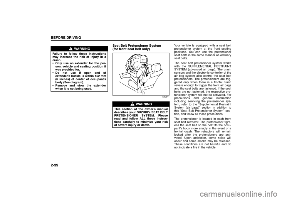
52D011
Your vehicle is equipped with a seat belt
pretensioner system at the front seating
positions. You can use the pretensioner
seat belts in the same manner as ordinary
seat belts.
The seat belt pretensioner system works
with the SUPPLEMENTAL RESTRAINT
SYSTEM (advanced air bags). The crash
sensors and the electronic controller of the
air bag system also control the seat belt
pretensioners. The pretensioners are trig-
gered only when there is a frontal crash
severe enough to trigger the front air bags
and the seat belts are fastened. If the seat
belts are not fastened, the respective pre-
tensioner system will not be activated. For
precautions and general information
including servicing the pretensioner sys-
tem, refer to the “Supplemental Restraint
System (air bags)” section in addition to
this “Seat Belt Pretensioner System” sec-
tion, and follow all those precautions.
The pretensioner is located in each front
seat belt retractor. The pretensioner tight-
ens the seat belt so the belt fits the occu-
pant’s body more snugly in the event of a
frontal crash. The retractors will remain
locked after the pretensioners are acti-
vated. Upon activation, some noise will
occur and some smoke may be released.
These conditions are not harmful and do
not indicate a fire in the vehicle.
WARNING
Failure to follow these instructions
may increase the risk of injury in a
crash.
Only use an extender for the per-
son, vehicle and seating position it
was provided for.
Do not use if open end of
extender’s buckle is within 152 mm
(6 inches) of center of occupant’s
body (See diagram).
Remove and stow the extender
when it is not being used.
WARNING
This section of the owner’s manual
describes your SUZUKI’s SEAT BELT
PRETENSIONER SYSTEM. Please
read and follow ALL these instruc-
tions carefully to minimize your risk
of severe injury or death.
Supplemental Restraint System (advanced air bags):
3, 9, 12
Page 53 of 278
2-40
BEFORE DRIVING
80J21-03E
The driver and all passengers must be
properly restrained by wearing seat belts
at all times, whether or not a pretensioner
is equipped at their seating position, to
minimize the risk of severe injury or death
in the event of a crash. Sit fully back in the
seat; sit up straight; do not lean forward or
sideways. Adjust the belt so the lap portion
of the belt is worn low across the pelvis,
not across the waist. Please refer to the
“Seat Adjustment” section and the instruc-
tions and precautions about the seat belts
in this “Seat Belts and Child Restraint Sys-
tems” section for details on proper seat
and seat belt adjustments.
Please note that the pretensioners along
with the front air bags will activate only in
severe frontal collisions. They are not
designed to activate in rear impacts, side
impacts, rollovers or minor frontal colli-
sions. The pretensioners can be activated
only once. If the pretensioners are acti-
vated (that is, if the front air bags are acti-
vated), have the pretensioner system
serviced by an authorized SUZUKI dealer
as soon as possible.
If the AIR BAG light on the instrument clus-
ter does not blink or come on briefly when
the ignition switch is turned to the “ON”
position, stays on for more than 10 sec-
onds, or comes on while driving, the pre-
tensioner system or the air bag system
may not work properly. Have both systems
inspected by an authorized SUZUKI dealer
as soon as possible.Service on or around the pretensioner sys-
tem components or wiring must be per-
formed only by an authorized SUZUKI
dealer who is specially trained. Improper
service could result in unintended activa-
tion of pretensioners or could render the
pretensioner inoperative. Either of these
two conditions may result in personal
injury.
To prevent damage or unintended activa-
tion of the pretensioners, be sure the bat-
tery is disconnected and the ignition switch
has been in the “LOCK” position for at least
90 seconds before performing any electri-
cal service work on your SUZUKI. Do not
touch pretensioner system components or
wiring. The wires are wrapped with yellow
tape or yellow tubing, and the couplers are
yellow. When scrapping your SUZUKI, ask
your SUZUKI dealer, body repair shop or
scrap yard for assistance.
Supplemental Restraint
System (air bags)
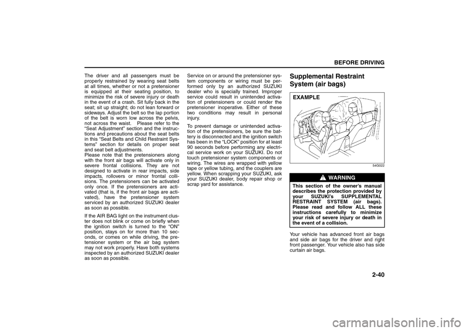
54G022
Your vehicle has advanced front air bags
and side air bags for the driver and right
front passenger. Your vehicle also has side
curtain air bags.
WARNING
This section of the owner’s manual
describes the protection provided by
your SUZUKI’s SUPPLEMENTAL
RESTRAINT SYSTEM (air bags).
Please read and follow ALL these
instructions carefully to minimize
your risk of severe injury or death in
the event of a collision.EXAMPLE
Supplemental Restraint System (advanced air bags):
3, 9, 12
Page 63 of 278
2-50
BEFORE DRIVING
80J21-03E
Service on or around air bag components
or wiring must be performed only by an
authorized SUZUKI dealer. Improper ser-
vice could result in unintended air bag
deployment or could render the air bags
inoperative. Either of these two conditions
may result in severe injury.
To prevent damage or unintended inflation
of the air bag system, be sure the battery
is disconnected and the ignition switch has
been in the “LOCK” position for at least 90
seconds before performing any electrical
service work on your SUZUKI. Do not
touch air bag system components or wires.
The wires are wrapped with yellow tape or
yellow tubing, and the couplers are yellow
for easy identification.
Scrapping a car that has an undeployed air
bag can be hazardous. Ask your dealer,
body repair shop or scrap yard for help
with disposal.
If it is necessary to modify the advanced
front air bag system to accommodate a
person with disabilities, owners in the con-
tinental United States can call American
Suzuki toll-free at 1-800-934-0934, or write
to:
American Suzuki Motor Corporation
Automotive Customer Relations
3251 East Imperial Highway
Brea, CA 92821-6795If you purchased your SUZUKI in Canada
please contact the Suzuki Canada Cus-
tomer Relations Department by telephone
at 1-905-889-2677 extension 2254 or in
writing at:
Suzuki Canada Inc.
Customer Relations
100 East Beaver Creek Road
Richmond Hill, On
L4B 1J6
Page 65 of 278
STEERING COLUMN CONTROLS
3
80J21-03E
60G405
STEERING COLUMN CONTROLSIgnition Switch ..................................................................... 3-1
Lighting/Turn Signal Control Lever ................................... 3-5
Windshield Wiper and Washer Lever ................................ 3-6
Rear Window Wiper/Washer Switch (if equipped) ........... 3-8
Tilt Steering Lock Lever (if equipped) ............................... 3-8
Cruise Control (if equipped) ............................................... 3-9
Remote Audio Controls (if equipped) ............................... 3-11
Horn ...................................................................................... 3-11
Page 66 of 278

3-1STEERING COLUMN CONTROLS
80J21-03E
65D611
Ignition Switch
60B041
The ignition switch has the following four
positions:
LOCK
This is the normal parking position. It is the
only position in which the key can be
removed.Manual transaxle
60A055
Manual transaxle vehicles
You must push in the key to turn it to the
“LOCK” position. It locks the ignition, and
prevents normal use of the steering
wheel after the key is removed.
Automatic transaxle vehicles
The gearshift lever must be in the “P”
(Park) position to turn the key to the
“LOCK” position. It locks the ignition and
prevents normal use of the steering
wheel and gearshift lever.
WARNING
To avoid possible injury, do not oper-
ate controls by reaching through the
steering wheel.
Push
Turn to “LOCK”
Ignition Switch: 8
Page 67 of 278
3-2
STEERING COLUMN CONTROLS
80J21-03E
60A300S
ACC
Accessories such as the radio can oper-
ate, but the engine is off.
ON
This is the normal operating position. All
electrical systems are on.
START
This is the position for starting the engine
using the starter motor. The key should be
released from this position as soon as the
engine starts.
Ignition key reminder
A buzzer sounds intermittently to remind
you to remove the ignition key if it is in the
ignition switch when the driver’s door is
opened.
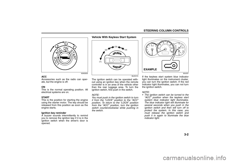
Vehicle With Keyless Start System
80JC010
The ignition switch can be operated with-
out using an ignition key when the remote
controller is in an area of the vehicle other
than the rear luggage area. To turn the
ignition switch, first push in the switch.
NOTE:
You must push in the ignition switch to turn
it from the “LOCK” position to the “ACC”
position. To return to the “LOCK” position
from the “ACC” position, turn the ignition
switch counterclockwise while pushing in
the switch.
80J037
If the keyless start system blue indicator
light illuminates on the instrument cluster,
you can turn the ignition switch. If the red
indicator light illuminates, you can not turn
the ignition switch.
NOTE:
The ignition switch can be turned to the
“ACC” position when the keyless start
system blue indicator light illuminates.
The blue indicator light will illuminate for
several seconds when you push in the
ignition switch and then will turn off to
protect the system. In this case, you
must release the ignition switch and
push it in again to illuminate the blue
indicator light.
(1)(2)(3)
(4)
EXAMPLE
Ignition Switch: 8
Page 68 of 278

3-3STEERING COLUMN CONTROLS
80J21-03E
If the keyless start system red indicator
light illuminates, the remote controller
may not be in the vehicle or the battery
of the remote controller may be unreli-
able.
NOTE:
If the battery of the remote controller
runs down or there are strong radio
waves or noise, the operating range may
be narrower or the remote controller may
be inoperative.
If the remote controller is too close to the
door glass, it may not operate.
The ignition switch may not turn when
the remote controller is on the instru-
ment panel, in the glove box, in the door
pocket, in the sun visor or on the floor.
You can also turn the ignition switch by
inserting the ignition key into the slot.The ignition switch has the following four
positions:
LOCK (1)
This is the normal parking position. It is the
only position in which the key can be
removed. It locks the ignition, and prevents
normal use of the steering wheel.
For vehicles with an automatic transaxle,
the gearshift lever must be in the “P” (Park)
position to turn the key to the “LOCK” posi-
tion.
To release the steering lock, turn the igni-
tion switch clockwise to one of the other
positions. If you have trouble turning the
ignition switch to unlock the steering, try
turning the steering wheel slightly to the
right or left while turning the switch.
NOTE:
You must push the ignition switch in to turn
it to the “ACC” position. Also you must
push the ignition switch in to return it to the
“LOCK” position.
ACC (2)
Accessories such as the radio can oper-
ate, but the engine is off.
ON (3)
This is the normal operating position. All
electrical systems are on.START (4)
This is the position for starting the engine
using the starter motor. The switch should
be released from this position as soon as
the engine starts.
Ignition switch reminder
(When using the keyless start system)
A buzzer sounds intermittently to remind
you to return the ignition switch to the
“LOCK” position if it is in the “ACC” position
when the driver’s door is opened.
Ignition key reminder
(When using the ignition key)
A buzzer sounds intermittently to remind
you to remove the ignition key if it is in the
ignition switch when the driver’s door is
opened.
CAUTION
The remote controller is a sensitive
electronic instrument. To avoid dam-
aging the remote controller:
Do not expose it to impacts, mois-
ture or high temperature such as by
leaving it on the dashboard under
direct sunlight.
Keep the remote controller away
from magnetic objects such as a
television.
Lighting/Turn Signal Control Lever: 8
Page 69 of 278

3-4
STEERING COLUMN CONTROLS
80J21-03E
62J083
If the gearshift lever can not be shifted out
of “P” (Park) in the normal way, removing
the cover (1) and pushing the release but-
ton using a key or some other flat end
object with the key in the “ON” or “ACC”
position will permit movement of the gear-
shift lever out of “P” (see “If You Can Not
Shift Automatic Transaxle Gearshift Lever
Out of “P” (PARK)” in the INDEX). The
gearshift lever can be moved back to “P”
without pushing the release button.
To release the steering lock, insert the key
or use the keyless start system and turn
the ignition switch clockwise to one of the
other positions. If you have trouble turning
the key to unlock the steering, try turning
the steering wheel slightly to the right or
left while turning the key.
81A297S
(1)
WARNING
For manual transaxle vehicles,
never remove the ignition key while
the vehicle is moving. The steering
wheel will lock and you will not be
able to steer the vehicle.
Always remove the ignition key
when leaving the vehicle even if a
short time. Also do not leave chil-
dren or pets alone in a parked vehi-
cle. Unattended children could
cause accidental movement of the
vehicle or could tamper with power
windows. Children or pets could
suffer from heatstroke in warm or
hot weather, which could result in
severe injury or even death.
CAUTION
Do not turn the starter motor for
more than 15 seconds at a time. If
the engine does not start, wait 15
seconds before trying again. If the
engine does not start after several
attempts, check the fuel and igni-
tion systems or consult your
SUZUKI dealer.
Do not leave the ignition switch in
the “ON” position if the engine is
not running or the battery will dis-
charge.
Lighting/Turn Signal Control Lever: 8
Windshield Wiper and Washer Lever: 8