2008 NISSAN TIIDA Canister
[x] Cancel search: CanisterPage 1078 of 2771

EC-4
Diagnosis Procedure .............................................260
DTC P0172 FUEL INJECTION SYSTEM
FUNCTION .......................................................
264
On Board Diagnosis Logic .....................................264
DTC Confirmation Procedure ................................264
Wiring Diagram ......................................................266
Diagnosis Procedure .............................................267
DTC P0181 FTT SENSOR ...............................270
Component Description .........................................270
On Board Diagnosis Logic .....................................270
DTC Confirmation Procedure ................................270
Wiring Diagram ......................................................271
Diagnosis Procedure .............................................271
Component Inspection ...........................................273
Removal and Installation .......................................273
DTC P0182, P0183 FTT SENSOR ..................274
Component Description .........................................274
On Board Diagnosis Logic .....................................274
DTC Confirmation Procedure ................................274
Wiring Diagram ......................................................275
Diagnosis Procedure .............................................275
Component Inspection ...........................................277
Removal and Installation .......................................277
DTC P0222, P0223 TP SENSOR ....................278
Component Description .........................................278
CONSULT-II Reference Value in Data Monitor
Mode ......................................................................
278
On Board Diagnosis Logic .....................................278
DTC Confirmation Procedure ................................278
Wiring Diagram ......................................................280
Diagnosis Procedure .............................................281
Component Inspection ...........................................283
Removal and Installation .......................................283
DTC P0300 - P0304 MULTIPLE CYLINDER
MISFIRE, NO. 1 - 4 CYLINDER MISFIRE .......
284
On Board Diagnosis Logic .....................................284
DTC Confirmation Procedure ................................284
Diagnosis Procedure .............................................285
DTC P0327, P0328 KS ....................................291
Component Description .........................................291
On Board Diagnosis Logic .....................................291
DTC Confirmation Procedure ................................291
Wiring Diagram ......................................................292
Diagnosis Procedure .............................................293
Component Inspection ...........................................294
Removal and Installation .......................................294
DTC P0335 CKP SENSOR (POS) ...................295
Component Description .........................................295
CONSULT-II Reference Value in Data Monitor
Mode ......................................................................
295
On Board Diagnosis Logic .....................................295
DTC Confirmation Procedure ................................295
Wiring Diagram ......................................................297
Diagnosis Procedure .............................................298
Component Inspection ..........................................301
Removal and Installation .......................................301
DTC P0340 CMP SENSOR (PHASE) ..............302
Component Description ........................................302
CONSULT-II Reference Value in Data Monitor
Mode .....................................................................
302
On Board Diagnosis Logic ....................................302
DTC Confirmation Procedure ................................302
Wiring Diagram .....................................................304
Diagnosis Procedure .............................................305
Component Inspection ..........................................307
Removal and Installation .......................................307
DTC P0420 THREE WAY CATALYST FUNC-
TION ..................................................................
308
On Board Diagnosis Logic ....................................308
DTC Confirmation Procedure ................................308
Overall Function Check .........................................309
Diagnosis Procedure .............................................310
DTC P0441 EVAP CONTROL SYSTEM ..........313
System Description ...............................................313
On Board Diagnosis Logic ....................................313
DTC Confirmation Procedure ................................313
Overall Function Check .........................................314
Diagnosis Procedure .............................................315
DTC P0442 EVAP CONTROL SYSTEM ..........318
On Board Diagnosis Logic ....................................318
DTC Confirmation Procedure ................................318
Diagnosis Procedure .............................................320
DTC P0443 EVAP CANISTER PURGE VOL-
UME CONTROL SOLENOID VALVE ...............
325
Description ............................................................325
CONSULT-II Reference Value in Data Monitor
Mode .....................................................................
325
On Board Diagnosis Logic ....................................326
DTC Confirmation Procedure ................................326
Wiring Diagram .....................................................327
Diagnosis Procedure .............................................328
Component Inspection ..........................................331
Removal and Installation .......................................331
DTC P0444, P0445 EVAP CANISTER PURGE
VOLUME CONTROL SOLENOID VALVE .......
332
Description ............................................................332
CONSULT-II Reference Value in Data Monitor
Mode .....................................................................
332
On Board Diagnosis Logic ....................................333
DTC Confirmation Procedure ................................333
Wiring Diagram .....................................................334
Diagnosis Procedure .............................................335
Component Inspection ..........................................337
Removal and Installation .......................................337
DTC P0447 EVAP CANISTER VENT CON-
TROL VALVE ...................................................
338
Page 1079 of 2771
EC-5
C
D
E
F
G
H
I
J
K
L
M
ECA
N
O
P Component Description .........................................
338
CONSULT-II Reference Value in Data Monitor
Mode .....................................................................
338
On Board Diagnosis Logic ....................................338
DTC Confirmation Procedure ................................338
Wiring Diagram .....................................................340
Diagnosis Procedure .............................................341
Component Inspection ..........................................343
DTC P0448 EVAP CANISTER VENT CON-
TROL VALVE ...................................................
345
Component Description .........................................345
CONSULT-II Reference Value in Data Monitor
Mode .....................................................................
345
On Board Diagnosis Logic ....................................345
DTC Confirmation Procedure ................................345
Wiring Diagram .....................................................347
Diagnosis Procedure .............................................348
Component Inspection ..........................................349
DTC P0451 EVAP CONTROL SYSTEM
PRESSURE SENSOR ......................................
351
Component Description .........................................351
CONSULT-II Reference Value in Data Monitor
Mode .....................................................................
351
On Board Diagnosis Logic ....................................351
DTC Confirmation Procedure ................................351
Diagnosis Procedure .............................................352
Component Inspection ..........................................353
DTC P0452 EVAP CONTROL SYSTEM
PRESSURE SENSOR ......................................
355
Component Description .........................................355
CONSULT-II Reference Value in Data Monitor
Mode .....................................................................
355
On Board Diagnosis Logic ....................................355
DTC Confirmation Procedure ................................355
Wiring Diagram .....................................................357
Diagnosis Procedure .............................................358
Component Inspection ..........................................361
DTC P0453 EVAP CONTROL SYSTEM
PRESSURE SENSOR ......................................
362
Component Description .........................................362
CONSULT-II Reference Value in Data Monitor
Mode .....................................................................
362
On Board Diagnosis Logic ....................................362
DTC Confirmation Procedure ................................362
Wiring Diagram .....................................................364
Diagnosis Procedure .............................................365
Component Inspection ..........................................369
DTC P0455 EVAP CONTROL SYSTEM ..........370
On Board Diagnosis Logic ....................................370
DTC Confirmation Procedure ................................370
Diagnosis Procedure .............................................372
DTC P0456 EVAP CONTROL SYSTEM ..........377
On Board Diagnosis Logic ....................................377
DTC Confirmation Procedure ................................378
Overall Function Check .........................................378
Diagnosis Procedure .............................................379
DTC P0460 FUEL LEVEL SENSOR ...............385
Component Description .........................................385
On Board Diagnosis Logic .....................................385
DTC Confirmation Procedure ................................385
Diagnosis Procedure .............................................386
Removal and Installation .......................................386
DTC P0461 FUEL LEVEL SENSOR ...............387
Component Description .........................................387
On Board Diagnosis Logic .....................................387
Overall Function Check .........................................387
Diagnosis Procedure .............................................388
Removal and Installation .......................................388
DTC P0462, P0463 FUEL LEVEL SENSOR ..389
Component Description .........................................389
On Board Diagnosis Logic .....................................389
DTC Confirmation Procedure ................................389
Diagnosis Procedure .............................................390
Removal and Installation .......................................390
DTC P0500 VSS ..............................................391
Description .............................................................391
On Board Diagnosis Logic .....................................391
DTC Confirmation Procedure ................................391
Overall Function Check .........................................392
Diagnosis Procedure .............................................392
DTC P0506 ISC SYSTEM ...............................393
Description .............................................................393
On Board Diagnosis Logic .....................................393
DTC Confirmation Procedure ................................393
Diagnosis Procedure .............................................393
DTC P0507 ISC SYSTEM ...............................395
Description .............................................................395
On Board Diagnosis Logic .....................................395
DTC Confirmation Procedure ................................395
Diagnosis Procedure .............................................395
DTC P0605 ECM .............................................397
Component Description .........................................397
On Board Diagnosis Logic .....................................397
DTC Confirmation Procedure ................................397
Diagnosis Procedure .............................................398
DTC P0643 SENSOR POWER SUPPLY ........400
On Board Diagnosis Logic .....................................400
DTC Confirmation Procedure ................................400
Wiring Diagram ......................................................401
Diagnosis Procedure .............................................402
DTC P0850 PNP SWITCH ..............................405
Component Description .........................................405
CONSULT-II Reference Value in Data Monitor
Mode ......................................................................
405
On Board Diagnosis Logic .....................................405
DTC Confirmation Procedure ................................405
Page 1105 of 2771
EVAPORATIVE EMISSION SYSTEM
EC-31
< SERVICE INFORMATION >
C
D
E
F
G
H
I
J
K
L
MA
EC
N
P O
EVAPORATIVE EMISSION SYSTEM
DescriptionINFOID:0000000001702563
SYSTEM DESCRIPTION
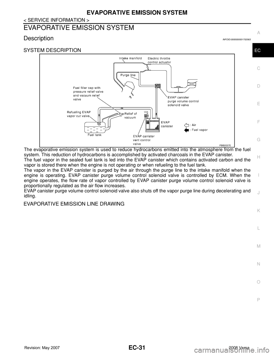
The evaporative emission system is used to reduce hydrocarbons emitted into the atmosphere from the fuel
system. This reduction of hydrocarbons is accomplished by activated charcoals in the EVAP canister.
The fuel vapor in the sealed fuel tank is led into the EVAP canister which contains activated carbon and the
vapor is stored there when the engine is not operating or when refueling to the fuel tank.
The vapor in the EVAP canister is purged by the air through the purge line to the intake manifold when the
engine is operating. EVAP canister purge volume control solenoid valve is controlled by ECM. When the
engine operates, the flow rate of vapor controlled by EVAP canister purge volume control solenoid valve is
proportionally regulated as the air flow increases.
EVAP canister purge volume control solenoid valve also shuts off the vapor purge line during decelerating and
idling.
EVAPORATIVE EMISSION LINE DRAWING
PBIB2037E
Page 1106 of 2771

EC-32
< SERVICE INFORMATION >
EVAPORATIVE EMISSION SYSTEM
NOTE: Do not use soapy water or any type of solvent while installing vacuum hose or purge hoses.
:Vehicle front
:From next page
1. Intake manifold collector 2. EVAP canister purge volume con-
trol solenoid valve3. EVAP service port
4. EVAP purge resonator
PBIB3330E
Page 1107 of 2771

EVAPORATIVE EMISSION SYSTEM
EC-33
< SERVICE INFORMATION >
C
D
E
F
G
H
I
J
K
L
MA
EC
N
P O
Component InspectionINFOID:0000000001702564
EVAP CANISTER
:To previous page
1. EVAP control system pressure sensor 2. EVAP canister 3. EVAP canister vent control valve
NOTE: Do not use soapy water or any type of solvent while installing vacuum hose or purge hoses.
BBIA0692E
Page 1108 of 2771
EC-34
< SERVICE INFORMATION >
EVAPORATIVE EMISSION SYSTEM
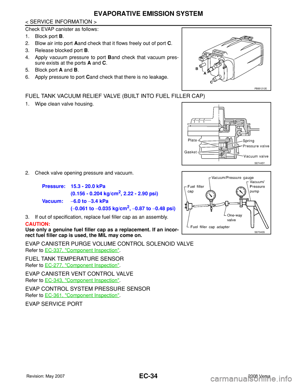
Check EVAP canister as follows:
1. Block port B.
2. Blow air into port Aand check that it flows freely out of port C.
3. Release blocked port B.
4. Apply vacuum pressure to port Band check that vacuum pres-
sure exists at the ports A and C.
5. Block port A and B.
6. Apply pressure to port Cand check that there is no leakage.
FUEL TANK VACUUM RELIEF VALVE (BUILT INTO FUEL FILLER CAP)
1. Wipe clean valve housing.
2. Check valve opening pressure and vacuum.
3. If out of specification, replace fuel filler cap as an assembly.
CAUTION:
Use only a genuine fuel filler cap as a replacement. If an incor-
rect fuel filler cap is used, the MIL may come on.
EVAP CANISTER PURGE VOLUME CONTROL SOLENOID VALVE
Refer to EC-337, "Component Inspection".
FUEL TANK TEMPERATURE SENSOR
Refer to EC-277, "Component Inspection".
EVAP CANISTER VENT CONTROL VALVE
Refer to EC-343, "Component Inspection".
EVAP CONTROL SYSTEM PRESSURE SENSOR
Refer to EC-361, "Component Inspection".
EVAP SERVICE PORT
PBIB1212E
SEF445Y
Pressure: 15.3 - 20.0 kPa
(0.156 - 0.204 kg/cm
2, 2.22 - 2.90 psi)
Vacuum:−6.0 to −3.4 kPa
(−0.061 to −0.035 kg/cm
2, −0.87 to −0.48 psi)
SEF943S
Page 1109 of 2771
EVAPORATIVE EMISSION SYSTEM
EC-35
< SERVICE INFORMATION >
C
D
E
F
G
H
I
J
K
L
MA
EC
N
P O
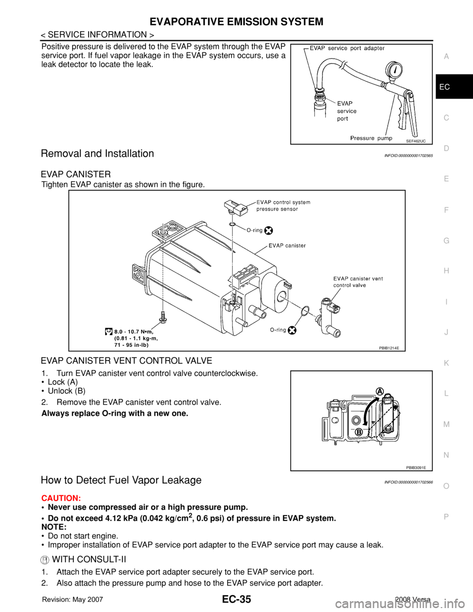
Positive pressure is delivered to the EVAP system through the EVAP
service port. If fuel vapor leakage in the EVAP system occurs, use a
leak detector to locate the leak.
Removal and InstallationINFOID:0000000001702565
EVAP CANISTER
Tighten EVAP canister as shown in the figure.
EVAP CANISTER VENT CONTROL VALVE
1. Turn EVAP canister vent control valve counterclockwise.
• Lock (A)
• Unlock (B)
2. Remove the EVAP canister vent control valve.
Always replace O-ring with a new one.
How to Detect Fuel Vapor LeakageINFOID:0000000001702566
CAUTION:
• Never use compressed air or a high pressure pump.
• Do not exceed 4.12 kPa (0.042 kg/cm
2, 0.6 psi) of pressure in EVAP system.
NOTE:
• Do not start engine.
• Improper installation of EVAP service port adapter to the EVAP service port may cause a leak.
WITH CONSULT-II
1. Attach the EVAP service port adapter securely to the EVAP service port.
2. Also attach the pressure pump and hose to the EVAP service port adapter.
SEF462UC
PBIB1214E
PBIB3091E
Page 1111 of 2771

EVAPORATIVE EMISSION SYSTEM
EC-37
< SERVICE INFORMATION >
C
D
E
F
G
H
I
J
K
L
MA
EC
N
P O
3. Apply battery voltage to the terminal of EVAP canister vent con-
trol valve (3) to make a closed EVAP system.
• EVAP control system pressure sensor (1)
• EVAP canister (2)
4. To locate the leak, deliver positive pressure to the EVAP system until pressure gauge points reach 1.38 to
2.76 kPa (0.014 to 0.028 kg/cm
2, 0.2 to 0.4 psi).
5. Remove EVAP service port adapter and hose with pressure pump.
6. Locate the leak using a leak detector. Refer to EC-31, "
Description".
BBIA0693E