2008 NISSAN TIIDA combination meter CAN
[x] Cancel search: combination meter CANPage 49 of 2771
ON BOARD DIAGNOSTIC (OBD) SYSTEM
AT-37
< SERVICE INFORMATION >
D
E
F
G
H
I
J
K
L
MA
B
AT
N
O
P
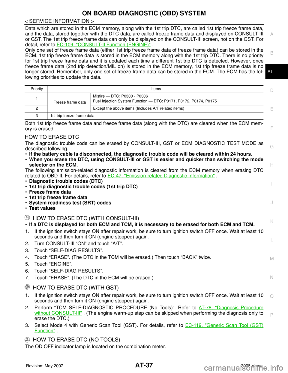
Data which are stored in the ECM memory, along with the 1st trip DTC, are called 1st trip freeze frame data,
and the data, stored together with the DTC data, are called freeze frame data and displayed on CONSULT-III
or GST. The 1st trip freeze frame data can only be displayed on the CONSULT-III screen, not on the GST. For
detail, refer to EC-109, "
CONSULT-II Function (ENGINE)" .
Only one set of freeze frame data (either 1st trip freeze frame data of freeze frame data) can be stored in the
ECM. 1st trip freeze frame data is stored in the ECM memory along with the 1st trip DTC. There is no priority
for 1st trip freeze frame data and it is updated each time a different 1st trip DTC is detected. However, once
freeze frame data (2nd trip detection/MIL on) is stored in the ECM memory, 1st trip freeze frame data is no
longer stored. Remember, only one set of freeze frame data can be stored in the ECM. The ECM has the fol-
lowing priorities to update the data.
Both 1st trip freeze frame data and freeze frame data (along with the DTC) are cleared when the ECM mem-
ory is erased.
HOW TO ERASE DTC
The diagnostic trouble code can be erased by CONSULT-III, GST or ECM DIAGNOSTIC TEST MODE as
described following.
•If the battery cable is disconnected, the diagnostic trouble code will be cleared within 24 hours.
•When you erase the DTC, using CONSULT-III or GST is easier and quicker than switching the mode
selector on the ECM.
The following emission-related diagnostic information is cleared from the ECM memory when erasing DTC
related to OBD-II. For details, refer to EC-47, "
Emission-related Diagnostic Information" .
•Diagnostic trouble codes (DTC)
•1st trip diagnostic trouble codes (1st trip DTC)
•Freeze frame data
•1st trip freeze frame data
•System readiness test (SRT) codes
•Test values
HOW TO ERASE DTC (WITH CONSULT-III)
•If a DTC is displayed for both ECM and TCM, it is necessary to be erased for both ECM and TCM.
1. If the ignition switch stays ON after repair work, be sure to turn ignition switch OFF once. Wait at least 10
seconds and then turn it ON (engine stopped) again.
2. Turn CONSULT-III “ON” and touch “A/T”.
3. Touch “SELF-DIAG RESULTS”.
4. Touch “ERASE”. (The DTC in the TCM will be erased.) Then touch “BACK” twice.
5. Touch “ENGINE”.
6. Touch “SELF-DIAG RESULTS”.
7. Touch “ERASE”. (The DTC in the ECM will be erased.)
HOW TO ERASE DTC (WITH GST)
1. If the ignition switch stays ON after repair work, be sure to turn ignition switch OFF once. Wait at least 10
seconds and then turn it ON (engine stopped) again.
2. Perform “TCM SELF-DIAGNOSTIC PROCEDURE (No Tools)”. Refer to AT-78, "
Diagnosis Procedure
without CONSULT-III" . (The engine warm-up step can be skipped when performing the diagnosis only to
erase the DTC.)
3. Select Mode 4 with Generic Scan Tool (GST). For details, refer to EC-119, "
Generic Scan Tool (GST)
Function" .
HOW TO ERASE DTC (NO TOOLS)
The OD OFF indicator lamp is located on the combination meter.
Priority Items
1
Freeze frame dataMisfire — DTC: P0300 - P0306
Fuel Injection System Function — DTC: P0171, P0172, P0174, P0175
2 Except the above items (Includes A/T related items)
3 1st trip freeze frame data
Page 51 of 2771
TROUBLE DIAGNOSIS
AT-39
< SERVICE INFORMATION >
D
E
F
G
H
I
J
K
L
MA
B
AT
N
O
P
TROUBLE DIAGNOSIS
DTC Inspection Priority ChartINFOID:0000000001703177
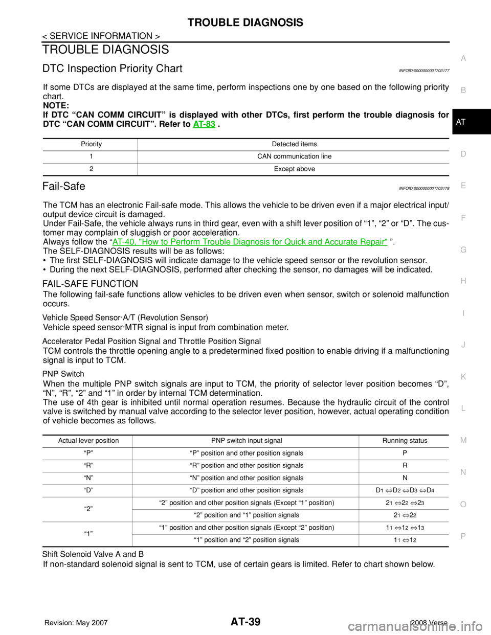
If some DTCs are displayed at the same time, perform inspections one by one based on the following priority
chart.
NOTE:
If DTC “CAN COMM CIRCUIT” is displayed with other DTCs, first perform the trouble diagnosis for
DTC “CAN COMM CIRCUIT”. Refer to AT- 8 3
.
Fail-SafeINFOID:0000000001703178
The TCM has an electronic Fail-safe mode. This allows the vehicle to be driven even if a major electrical input/
output device circuit is damaged.
Under Fail-Safe, the vehicle always runs in third gear, even with a shift lever position of “1”, “2” or “D”. The cus-
tomer may complain of sluggish or poor acceleration.
Always follow the “AT-40, "
How to Perform Trouble Diagnosis for Quick and Accurate Repair" ”.
The SELF-DIAGNOSIS results will be as follows:
• The first SELF-DIAGNOSIS will indicate damage to the vehicle speed sensor or the revolution sensor.
• During the next SELF-DIAGNOSIS, performed after checking the sensor, no damages will be indicated.
FAIL-SAFE FUNCTION
The following fail-safe functions allow vehicles to be driven even when sensor, switch or solenoid malfunction
occurs.
Vehicle Speed Sensor·A/T (Revolution Sensor)
Vehicle speed sensor·MTR signal is input from combination meter.
Accelerator Pedal Position Signal and Throttle Position Signal
TCM controls the throttle opening angle to a predetermined fixed position to enable driving if a malfunctioning
signal is input to TCM.
PNP Switch
When the multiple PNP switch signals are input to TCM, the priority of selector lever position becomes “D”,
“N”, “R”, “2” and “1” in order by internal TCM determination.
The use of 4th gear is inhibited until normal operation resumes. Because the hydraulic circuit of the control
valve is switched by manual valve according to the selector lever position, however, actual operating condition
of vehicle becomes as follows.
Shift Solenoid Valve A and B
If non-standard solenoid signal is sent to TCM, use of certain gears is limited. Refer to chart shown below.
Priority Detected items
1 CAN communication line
2 Except above
Actual lever position PNP switch input signal Running status
“P” “P” position and other position signals P
“R” “R” position and other position signals R
“N” “N” position and other position signals N
“D” “D” position and other position signals D
1 ⇔D2 ⇔D3 ⇔D4
“2”“2” position and other position signals (Except “1” position) 21 ⇔22 ⇔23
“2” position and “1” position signals 21 ⇔22
“1”“1” position and other position signals (Except “2” position) 11 ⇔12 ⇔13
“1” position and “2” position signals 11 ⇔12
Page 184 of 2771
AT-172
< SERVICE INFORMATION >
SHIFT POSITION INDICATOR CIRCUIT
SHIFT POSITION INDICATOR CIRCUIT
DescriptionINFOID:0000000001703331
TCM sends the switch signals to combination meter via CAN communication line. Then selector lever position
is indicated on the shift position indicator.
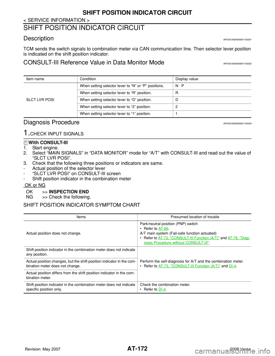
CONSULT-III Reference Value in Data Monitor ModeINFOID:0000000001703332
Diagnosis ProcedureINFOID:0000000001703333
1.CHECK INPUT SIGNALS
With CONSULT-III
1. Start engine.
2. Select “MAIN SIGNALS” in “DATA MONITOR” mode for “A/T” with CONSULT-III and read out the value of
“SLCT LVR POSI”.
3. Check that the following three positions or indicators are same.
- Actual position of the selector lever
- “SLCT LVR POSI” on CONSULT-III screen
- Shift position indicator in the combination meter
OK or NG
OK >>INSPECTION END
NG >> Check the following.
SHIFT POSITION INDICATOR SYMPTOM CHART
Item name Condition Display value
SLCT LVR POSIWhen setting selector lever to “N” or “P” positions. N · P
When setting selector lever to “R” position. R
When setting selector lever to “D” position. D
When setting selector lever to “2” position. 2
When setting selector lever to “1” position. 1
Items Presumed location of trouble
Actual position does not change.Park/neutral position (PNP) switch
• Refer to AT- 8 6
.
A/T main system (Fail-safe function actuated)
•Refer to AT- 7 3 , "
CONSULT-III Function (A/T)" and AT- 7 8 , "Diag-
nosis Procedure without CONSULT-III".
Shift position indicator in the combination meter does not indicate
any position.
Perform the self-diagnosis for A/T and the combination meter.
• Refer to AT- 7 3 , "
CONSULT-III Function (A/T)" and DI-4. Actual position changes, but the shift position indicator in the com-
bination meter does not change.
Actual position differs from the shift position indicator in the com-
bination meter.
Shift position indicator in the combination meter does not indicate
specific position only.Check the combination meter.
• Refer to DI-4
.
Page 190 of 2771
AT-178
< SERVICE INFORMATION >
TROUBLE DIAGNOSIS FOR SYMPTOMS
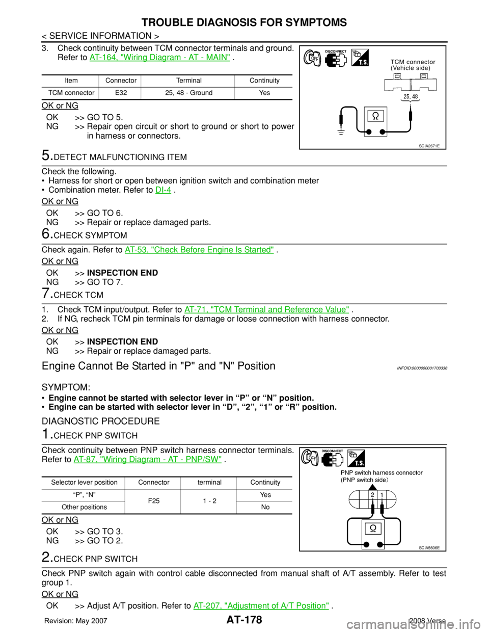
3. Check continuity between TCM connector terminals and ground.
Refer to AT-164, "
Wiring Diagram - AT - MAIN" .
OK or NG
OK >> GO TO 5.
NG >> Repair open circuit or short to ground or short to power
in harness or connectors.
5.DETECT MALFUNCTIONING ITEM
Check the following.
• Harness for short or open between ignition switch and combination meter
• Combination meter. Refer to DI-4
.
OK or NG
OK >> GO TO 6.
NG >> Repair or replace damaged parts.
6.CHECK SYMPTOM
Check again. Refer to AT-53, "
Check Before Engine Is Started" .
OK or NG
OK >>INSPECTION END
NG >> GO TO 7.
7.CHECK TCM
1. Check TCM input/output. Refer to AT-71, "
TCM Terminal and Reference Value" .
2. If NG, recheck TCM pin terminals for damage or loose connection with harness connector.
OK or NG
OK >>INSPECTION END
NG >> Repair or replace damaged parts.
Engine Cannot Be Started in "P" and "N" PositionINFOID:0000000001703336
SYMPTOM:
•Engine cannot be started with selector lever in “P” or “N” position.
•Engine can be started with selector lever in “D”, “2”, “1” or “R” position.
DIAGNOSTIC PROCEDURE
1.CHECK PNP SWITCH
Check continuity between PNP switch harness connector terminals.
Refer to AT-87, "
Wiring Diagram - AT - PNP/SW" .
OK or NG
OK >> GO TO 3.
NG >> GO TO 2.
2.CHECK PNP SWITCH
Check PNP switch again with control cable disconnected from manual shaft of A/T assembly. Refer to test
group 1.
OK or NG
OK >> Adjust A/T position. Refer to AT-207, "Adjustment of A/T Position" .
Item Connector Terminal Continuity
TCM connector E32 25, 48 - Ground Yes
SCIA2671E
Selector lever position Connector terminal Continuity
“P”, “N”
F25 1 - 2Ye s
Other positions No
SCIA5606E
Page 421 of 2771
BCM (BODY CONTROL MODULE)
BCS-5
< SERVICE INFORMATION >
C
D
E
F
G
H
I
J
L
MA
B
BCS
N
O
P
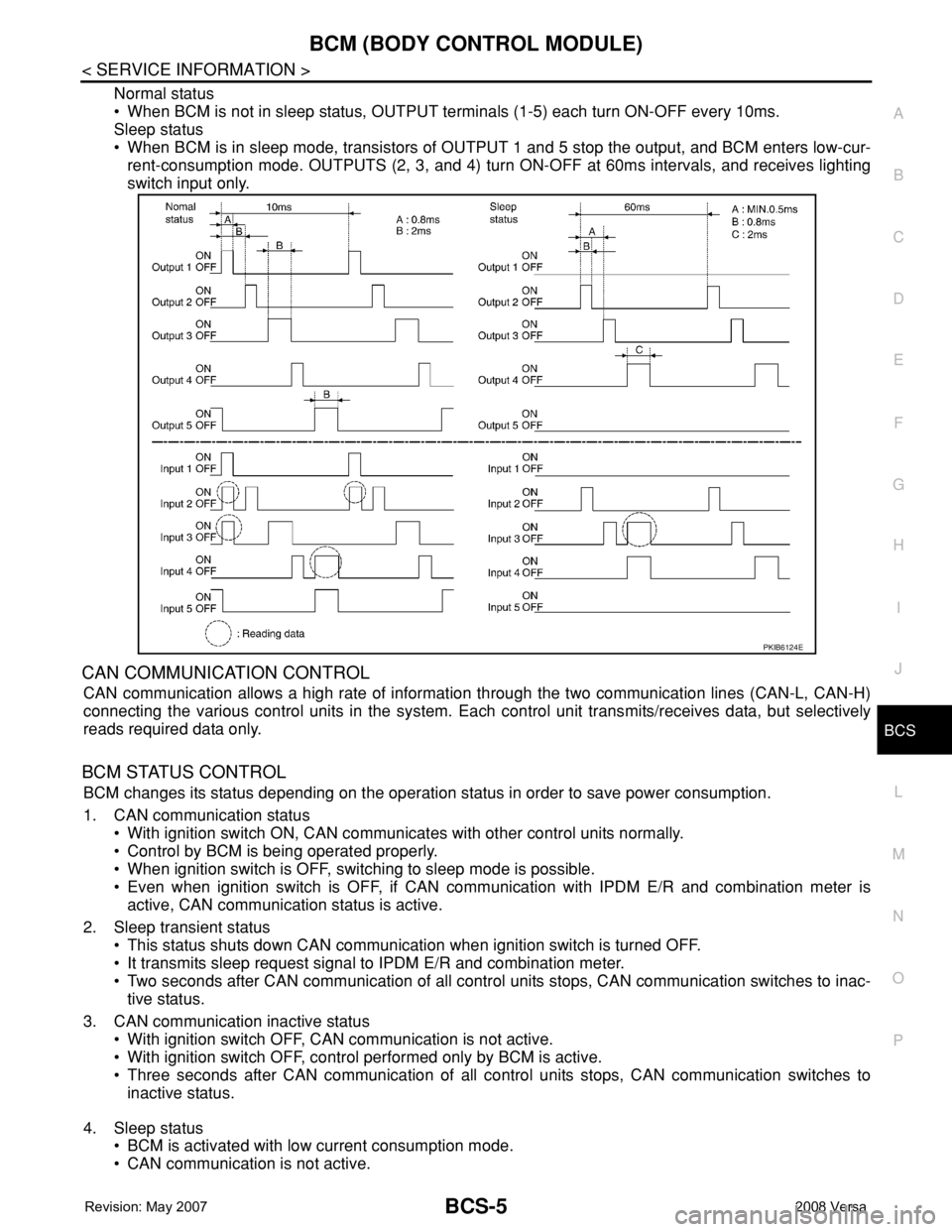
Normal status
• When BCM is not in sleep status, OUTPUT terminals (1-5) each turn ON-OFF every 10ms.
Sleep status
• When BCM is in sleep mode, transistors of OUTPUT 1 and 5 stop the output, and BCM enters low-cur-
rent-consumption mode. OUTPUTS (2, 3, and 4) turn ON-OFF at 60ms intervals, and receives lighting
switch input only.
CAN COMMUNICATION CONTROL
CAN communication allows a high rate of information through the two communication lines (CAN-L, CAN-H)
connecting the various control units in the system. Each control unit transmits/receives data, but selectively
reads required data only.
BCM STATUS CONTROL
BCM changes its status depending on the operation status in order to save power consumption.
1. CAN communication status
• With ignition switch ON, CAN communicates with other control units normally.
• Control by BCM is being operated properly.
• When ignition switch is OFF, switching to sleep mode is possible.
• Even when ignition switch is OFF, if CAN communication with IPDM E/R and combination meter is
active, CAN communication status is active.
2. Sleep transient status
• This status shuts down CAN communication when ignition switch is turned OFF.
• It transmits sleep request signal to IPDM E/R and combination meter.
• Two seconds after CAN communication of all control units stops, CAN communication switches to inac-
tive status.
3. CAN communication inactive status
• With ignition switch OFF, CAN communication is not active.
• With ignition switch OFF, control performed only by BCM is active.
• Three seconds after CAN communication of all control units stops, CAN communication switches to
inactive status.
4. Sleep status
• BCM is activated with low current consumption mode.
• CAN communication is not active.
PKIB6124E
Page 422 of 2771
BCS-6
< SERVICE INFORMATION >
BCM (BODY CONTROL MODULE)
• When CAN communication operation is detected, it switches to CAN communication status.
• When a state of the following switches changes, it switches to CAN communication state:
- Ignition switch
- Key switch (without Intelligent Key)
- Key switch and ignition knob switch (with Intelligent Key)
- Hazard switch
- Door lock/unlock switch
- Front door switch (LH, RH)
- Rear door switch (LH, RH)
- Back door lock assembly (Hatchback)
- Trunk key cylinder switch (Sedan)
- Trunk lamp switch and trunk release solenoid (Sedan)
- Combination switch (passing, lighting switch 1st position, front fog lamp)
- Keyfob (lock/unlock signal)
- Front door key cylinder switch LH
• When control performed only by BCM is required by switch, it shifts to CAN communication inactive
mode.
• Status of combination switch reading function is changed.
SYSTEMS CONTROLLED BY BCM DIRECTLY
• Power door lock system. Refer to BL-22 .
• Remote keyless entry system. Refer to BL-51
.
• Power window system. Refer to GW-18
. NOTE
• Sunroof system. Refer to RF-10. NOTE
• Room lamp timer. Refer to LT- 8 9 .
• Rear wiper and washer system. Refer to WW-24
.
NOTE:
Power supply only. No system control.
SYSTEMS CONTROLLED BY BCM AND IPDM E/R
• Panic system. Refer to BL-51 .
• Vehicle security (theft warning) system. Refer to BL-187
.
• NVIS(NATS) system. Refer to BL-210
.
• Headlamp, tail lamp and battery saver control systems. Refer to LT- 7 2
, LT- 4 or LT- 2 5 .
• Front fog lamp. Refer to LT- 3 9
.
• Front wiper and washer system. Refer to WW-3
.
• Rear window defogger system. Refer to GW-49
.
SYSTEMS CONTROLLED BY BCM AND COMBINATION METER
• Warning chime. Refer to DI-41 .
• Turn signal and hazard warning lamps. Refer to LT- 4 8
.
SYSTEMS CONTROLLED BY BCM AND INTELLIGENT KEY UNIT
• Intelligent Key system. Refer to BL-74 .
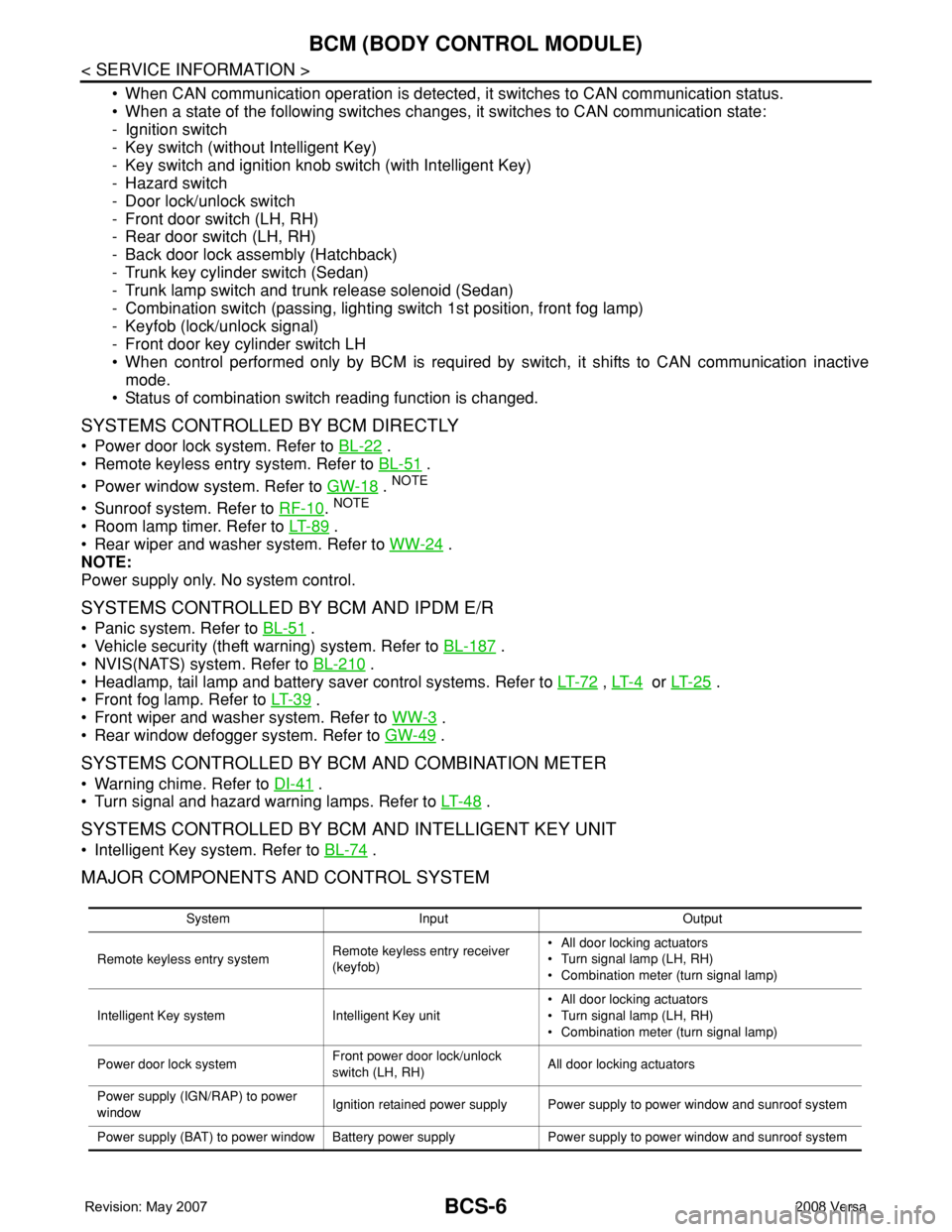
MAJOR COMPONENTS AND CONTROL SYSTEM
System Input Output
Remote keyless entry systemRemote keyless entry receiver
(keyfob)• All door locking actuators
• Turn signal lamp (LH, RH)
• Combination meter (turn signal lamp)
Intelligent Key system Intelligent Key unit• All door locking actuators
• Turn signal lamp (LH, RH)
• Combination meter (turn signal lamp)
Power door lock systemFront power door lock/unlock
switch (LH, RH)All door locking actuators
Power supply (IGN/RAP) to power
windowIgnition retained power supply Power supply to power window and sunroof system
Power supply (BAT) to power window Battery power supply Power supply to power window and sunroof system
Page 423 of 2771

BCM (BODY CONTROL MODULE)
BCS-7
< SERVICE INFORMATION >
C
D
E
F
G
H
I
J
L
MA
B
BCS
N
O
P
CAN Communication System DescriptionINFOID:0000000001704585
Refer to LAN-6, "System Description".
Panic alarm• Key switch
•KeyfobIPDM E/R
Vehicle security system• All door switches
•Keyfob
• Door lock/unlock switch
• Trunk key cylinder switch (Se-
dan)
• Front door key cylinder switch
LH• IPDM/ER
• Security indicator lamp
Battery saver control• Ignition switch
• Combination switchIPDM E/R
Headlamp Combination switch IPDM E/R
Tail lamp Combination switch IPDM E/R
Front fog lamp Combination switch IPDM E/R
Turn signal lamp Combination switch• Turn signal lamp
• Combination meter
Hazard lamp Hazard switch• Turn signal lamp
• Combination meter
Room lamp timer• Key switch
•Keyfob
• Main power window and door
lock/unlock switch
• Front door switch LH
• All door switchInterior room lamp
Back door switch signal (Hatchback) Back door lock assembly Luggage room lamp
Back door lock signal (Hatchback) Back door lock assembly Back door opener
Trunk lamp switch signalTrunk lamp switch and trunk re-
lease solenoidLuggage room lamp
Trunk lid opener signalTrunk lamp switch and trunk re-
lease solenoidTrunk lid opener
Key warning chime• Key switch
• Front door switch LHCombination meter (warning buzzer)
Light warning chime• Combination switch
• Key switch
• Front door switch LHCombination meter (warning buzzer)
Seat belt warning chime• Seat belt buckle switch LH
• Ignition switchCombination meter (warning buzzer)
Front wiper and washer system• Combination switch
• Ignition switchIPDM E/R
Rear window defogger Rear window defogger switch IPDM E/R
Rear wiper and washer system• Combination switch
• Ignition switchRear wiper motor
A/C switch signal Front air control ECM
Blower fan switch signal Front air control ECM
A/C indicator signal Front air control A/C indicator
Low tire pressure warning system Remote keyless entry receiver Combination meterSystem Input Output
Page 433 of 2771

BCM (BODY CONTROL MODULE)
BCS-17
< SERVICE INFORMATION >
C
D
E
F
G
H
I
J
L
MA
B
BCS
N
O
P
WORK SUPPORT
Display Item List
CAN Communication Inspection Using CONSULT-III (Self-Diagnosis)INFOID:0000000001704591
1.SELF-DIAGNOSTIC RESULT CHECK
1. Connect CONSULT–III and select “BCM” on “SELECT SYSTEM” screen.
2. Select “BCM” on “SELECT TEST ITEM” screen, and select “SELF-DIAG RESULTS”.
3. Check display content in self-diagnostic results.
Contents displayed
No malfunction>>Inspection End
Malfunction in CAN communication system>>After printing the monitor items, go to “CAN System”. Refer to
LAN-15, "
Trouble Diagnosis Flow Chart".
ConfigurationINFOID:0000000001806223
DESCRIPTION
CONFIGURATION has three functions as follows:
• READ CONFIGURATION is the function to read (extract) vehicle configuration of current BCM.
Blower fan switch sig-
nal
Air conditioner switch
signalAIR CONDITION-
ER×
Intelligent KeyINTELLIGENT
KEY×
Combination switch COMB SW×
NVIS (NATS) IMMU××
Interior lamp battery
saverBATTERY SAV-
ER×××
Back door/Trunk TRUNK××
Theft alarm THEFT ALARM×××
Retained accessory
power controlRETAINED PWR×××
Oil pressure switch SIGNAL BUFFER××
Low tire pressure moni-
torAIR PRESSURE
MONITOR×× × ×
Panic alarm PANIC ALARM× System and itemCONSULT-III dis-
playDiagnostic test mode (Inspection by part)
WORK
SUPPORTSELF−
DIAG RE-
SULTSCAN DIAG
SUPPORT
MNTRDATA
MONITORECU
PA R T
NUMBERAC-
TIVE
TESTCON-
FIGU-
RATION
Item Description
RESET SETTING VALUE Return a value set with WORK SUPPORT of each system to a default value in factory shipment.
CONSULT-III display code Diagnosis item
U1000INITIAL DIAG
TRANSMIT DIAG
ECM
IPDM E/R
METER/M&A
I-KEY