Page 1153 of 2771
BASIC SERVICE PROCEDURE
EC-79
< SERVICE INFORMATION >
C
D
E
F
G
H
I
J
K
L
MA
EC
N
P O
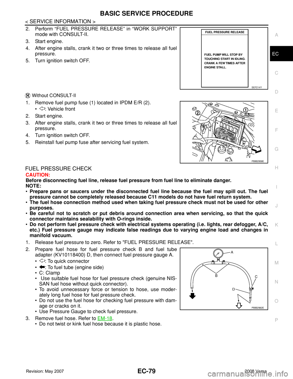
2. Perform “FUEL PRESSURE RELEASE” in “WORK SUPPORT”
mode with CONSULT-II.
3. Start engine.
4. After engine stalls, crank it two or three times to release all fuel
pressure.
5. Turn ignition switch OFF.
Without CONSULT-II
1. Remove fuel pump fuse (1) located in IPDM E/R (2).
• : Vehicle front
2. Start engine.
3. After engine stalls, crank it two or three times to release all fuel
pressure.
4. Turn ignition switch OFF.
5. Reinstall fuel pump fuse after servicing fuel system.
FUEL PRESSURE CHECK
CAUTION:
Before disconnecting fuel line, release fuel pressure from fuel line to eliminate danger.
NOTE:
•Prepare pans or saucers under the disconnected fuel line because the fuel may spill out. The fuel
pressure cannot be completely released because C11 models do not have fuel return system.
•The fuel hose connection method used when taking fuel pressure check must not be used for other
purposes.
•Be careful not to scratch or put debris around connection area when servicing, so that the quick
connector maintains sealability with O-rings inside.
•Do not perform fuel pressure check with electrical systems operating (i.e. lights, rear defogger, A/C,
etc.) Fuel pressure gauge may indicate false readings due to varying engine load and changes in
manifold vacuum.
1. Release fuel pressure to zero. Refer to "FUEL PRESSURE RELEASE".
2. Prepare fuel hose for fuel pressure check B and fuel tube
adapter (KV10118400) D, then connect fuel pressure gauge A.
• : To quick connector
• : To fuel tube (engine side)
• C: Clamp
• Use suitable fuel hose for fuel pressure check (genuine NIS-
SAN fuel hose without quick connector).
• To avoid unnecessary force or tension to hose, use moder-
ately long fuel hose for fuel pressure check.
• Do not use the fuel hose for checking fuel pressure with dam-
age or cracks on it.
• Use Pressure Gauge to check fuel pressure.
3. Remove fuel hose. Refer to EM-18
.
• Do not twist or kink fuel hose because it is plastic hose.
SEF214Y
PBIB2958E
PBIB2982E
Page 1165 of 2771

TROUBLE DIAGNOSIS
EC-91
< SERVICE INFORMATION >
C
D
E
F
G
H
I
J
K
L
MA
EC
N
P O
Air Air duct
55555 5EM-16
Air cleanerEM-16
Air leakage from air duct
(Mass air flow sensor — electric
throttle control actuator)
5555EM-16
Electric throttle control actuatorEM-18
Air leakage from intake manifold/
Collector/GasketEM-18
Cranking Battery
111111
11SC-4
Generator circuitSC-20
Starter circuit 3SC-8
Signal plate 6EM-76
Park/neutral position (PNP)
switch4MT-12, AT-
86 or
CVT-65
Engine Cylinder head
55555 55 5EM-62
Cylinder head gasket 4 3
Cylinder block
66666 66 64
EM-76
Piston
Piston ring
Connecting rod
Bearing
Crankshaft
Va l v e
mecha-
nismTiming chain
55555 55 5EM-37
CamshaftEM-47
Intake valve timing controlEM-37
Intake valve
3EM-62
Exhaust valve
Exhaust Exhaust manifold/Tube/Muffler/
Gasket
55555 55 5EM-21
, EX-
4Three way catalyst
Lubrica-
tionOil pan/Oil strainer/Oil pump/Oil
filter/Oil gallery
55555 55 5EM-24
, LU-
9
Oil level (Low)/Filthy oilLU-6
SYMPTOM
Reference
page
HARD/NO START/RESTART (EXCP. HA)
ENGINE STALL
HESITATION/SURGING/FLAT SPOT
SPARK KNOCK/DETONATION
LACK OF POWER/POOR ACCELERATION
HIGH IDLE/LOW IDLE
ROUGH IDLE/HUNTING
IDLING VIBRATION
SLOW/NO RETURN TO IDLE
OVERHEATS/WATER TEMPERATURE HIGH
EXCESSIVE FUEL CONSUMPTION
EXCESSIVE OIL CONSUMPTION
BATTERY DEAD (UNDER CHARGE)
Warranty symptom code AA AB AC AD AE AF AG AH AJ AK AL AM HA
Page 1271 of 2771
DTC P0122, P0123 TP SENSOR
EC-197
< SERVICE INFORMATION >
C
D
E
F
G
H
I
J
K
L
MA
EC
N
P O
>>INSPECTION END
7.CHECK INTERMITTENT INCIDENT
Refer to EC-136
.
>>INSPECTION END
Component InspectionINFOID:0000000001702685
THROTTLE POSITION SENSOR
1. Reconnect all harness connectors disconnected.
2. Perform EC-76, "
Throttle Valve Closed Position Learning".
3. Turn ignition switch ON.
4. Set shift lever to D position (A/T, CVT) or 1st position (M/T).
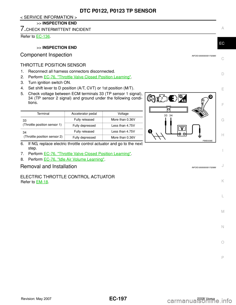
5. Check voltage between ECM terminals 33 (TP sensor 1 signal),
34 (TP sensor 2 signal) and ground under the following condi-
tions.
6. If NG, replace electric throttle control actuator and go to the next
step.
7. Perform EC-76, "
Throttle Valve Closed Position Learning".
8. Perform EC-76, "
Idle Air Volume Learning".
Removal and InstallationINFOID:0000000001702686
ELECTRIC THROTTLE CONTROL ACTUATOR
Refer to EM-18.
Terminal Accelerator pedal Voltage
33
(Throttle position sensor 1)Fully released More than 0.36V
Fully depressed Less than 4.75V
34
(Throttle position sensor 2)Fully released Less than 4.75V
Fully depressed More than 0.36V
PBIB3038E
Page 1357 of 2771
DTC P0222, P0223 TP SENSOR
EC-283
< SERVICE INFORMATION >
C
D
E
F
G
H
I
J
K
L
MA
EC
N
P O
>>INSPECTION END
7.CHECK INTERMITTENT INCIDENT
Refer to EC-136
.
>>INSPECTION END
Component InspectionINFOID:0000000001702788
THROTTLE POSITION SENSOR
1. Reconnect all harness connectors disconnected.
2. Perform EC-76, "
Throttle Valve Closed Position Learning".
3. Turn ignition switch ON.
4. Set shift lever to D position (A/T, CVT) or 1st position (M/T).
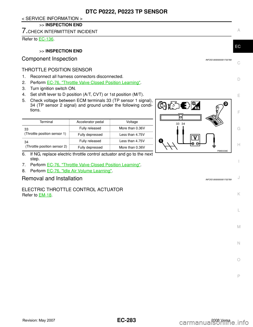
5. Check voltage between ECM terminals 33 (TP sensor 1 signal),
34 (TP sensor 2 signal) and ground under the following condi-
tions.
6. If NG, replace electric throttle control actuator and go to the next
step.
7. Perform EC-76, "
Throttle Valve Closed Position Learning".
8. Perform EC-76, "
Idle Air Volume Learning".
Removal and InstallationINFOID:0000000001702789
ELECTRIC THROTTLE CONTROL ACTUATOR
Refer to EM-18.
Terminal Accelerator pedal Voltage
33
(Throttle position sensor 1)Fully released More than 0.36V
Fully depressed Less than 4.75V
34
(Throttle position sensor 2)Fully released Less than 4.75V
Fully depressed More than 0.36V
PBIB3038E
Page 1405 of 2771
DTC P0443 EVAP CANISTER PURGE VOLUME CONTROL SOLENOID VALVE
EC-331
< SERVICE INFORMATION >
C
D
E
F
G
H
I
J
K
L
MA
EC
N
P O
>> Repair hose or replace EVAP canister.
13.CHECK INTERMITTENT INCIDENT
Refer to EC-136
.
>>INSPECTION END
Component InspectionINFOID:0000000001702834
EVAP CANISTER PURGE VOLUME CONTROL SOLENOID VALVE
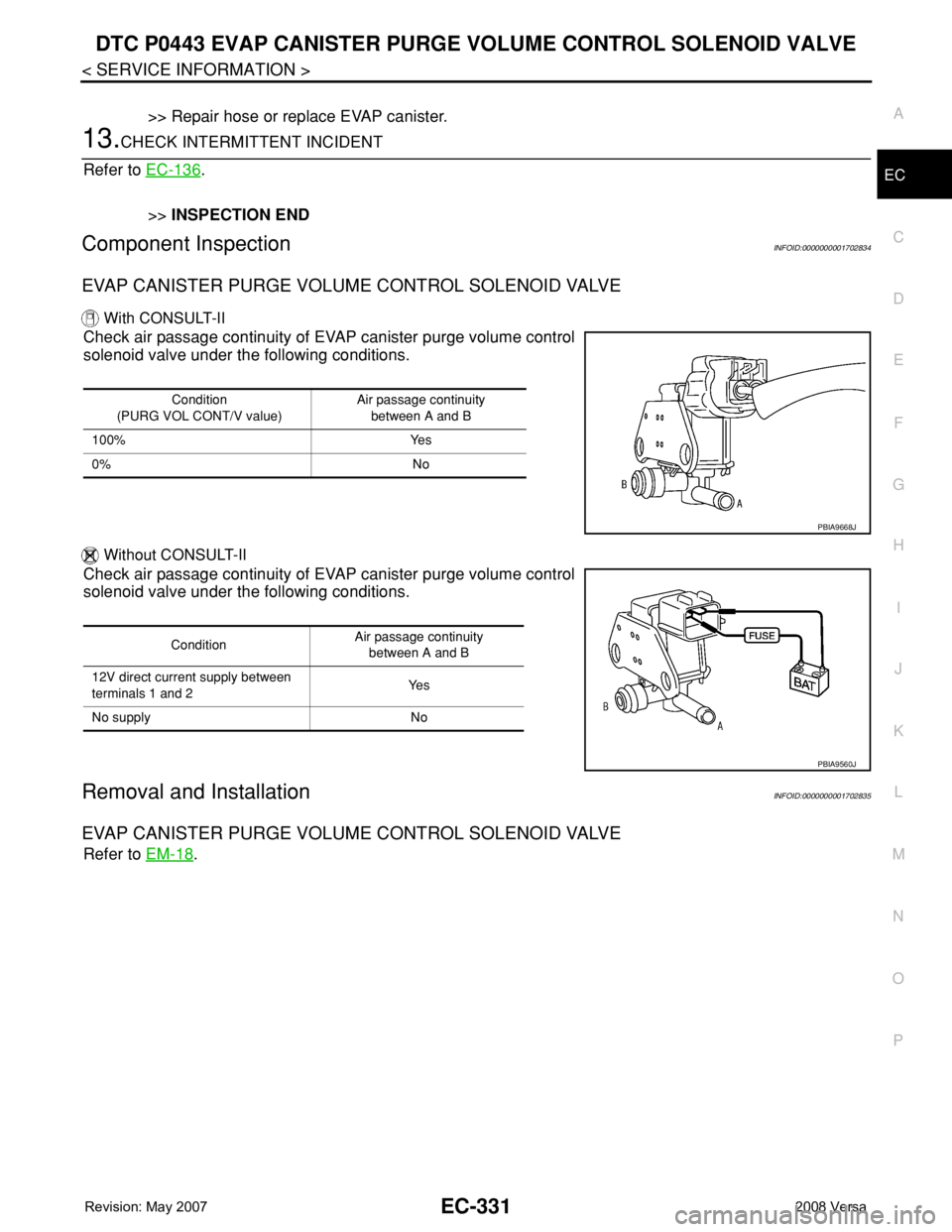
With CONSULT-II
Check air passage continuity of EVAP canister purge volume control
solenoid valve under the following conditions.
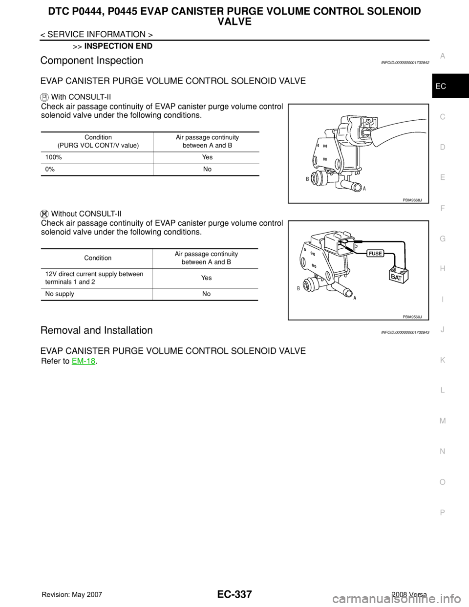
Without CONSULT-II
Check air passage continuity of EVAP canister purge volume control
solenoid valve under the following conditions.
Removal and InstallationINFOID:0000000001702835
EVAP CANISTER PURGE VOLUME CONTROL SOLENOID VALVE
Refer to EM-18.
Condition
(PURG VOL CONT/V value)Air passage continuity
between A and B
100% Yes
0% No
PBIA9668J
ConditionAir passage continuity
between A and B
12V direct current supply between
terminals 1 and 2Ye s
No supply No
PBIA9560J
Page 1411 of 2771
DTC P0444, P0445 EVAP CANISTER PURGE VOLUME CONTROL SOLENOID
VALVE
EC-337
< SERVICE INFORMATION >
C
D
E
F
G
H
I
J
K
L
MA
EC
N
P O
>>INSPECTION END
Component InspectionINFOID:0000000001702842
EVAP CANISTER PURGE VOLUME CONTROL SOLENOID VALVE
With CONSULT-II
Check air passage continuity of EVAP canister purge volume control
solenoid valve under the following conditions.
Without CONSULT-II
Check air passage continuity of EVAP canister purge volume control
solenoid valve under the following conditions.
Removal and InstallationINFOID:0000000001702843
EVAP CANISTER PURGE VOLUME CONTROL SOLENOID VALVE
Refer to EM-18.
Condition
(PURG VOL CONT/V value)Air passage continuity
between A and B
100% Yes
0% No
PBIA9668J
ConditionAir passage continuity
between A and B
12V direct current supply between
terminals 1 and 2Ye s
No supply No
PBIA9560J
Page 1501 of 2771
DTC P1225 TP SENSOR
EC-427
< SERVICE INFORMATION >
C
D
E
F
G
H
I
J
K
L
MA
EC
N
P O
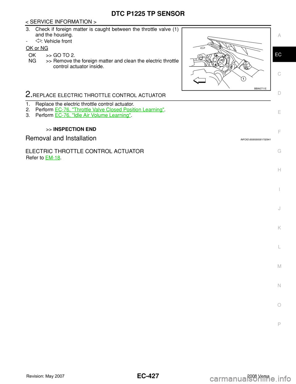
3. Check if foreign matter is caught between the throttle valve (1)
and the housing.
- : Vehicle front
OK or NG
OK >> GO TO 2.
NG >> Remove the foreign matter and clean the electric throttle
control actuator inside.
2.REPLACE ELECTRIC THROTTLE CONTROL ACTUATOR
1. Replace the electric throttle control actuator.
2. Perform EC-76, "
Throttle Valve Closed Position Learning".
3. Perform EC-76, "
Idle Air Volume Learning".
>>INSPECTION END
Removal and InstallationINFOID:0000000001702941
ELECTRIC THROTTLE CONTROL ACTUATOR
Refer to EM-18.
BBIA0711E
Page 1503 of 2771
DTC P1226 TP SENSOR
EC-429
< SERVICE INFORMATION >
C
D
E
F
G
H
I
J
K
L
MA
EC
N
P O
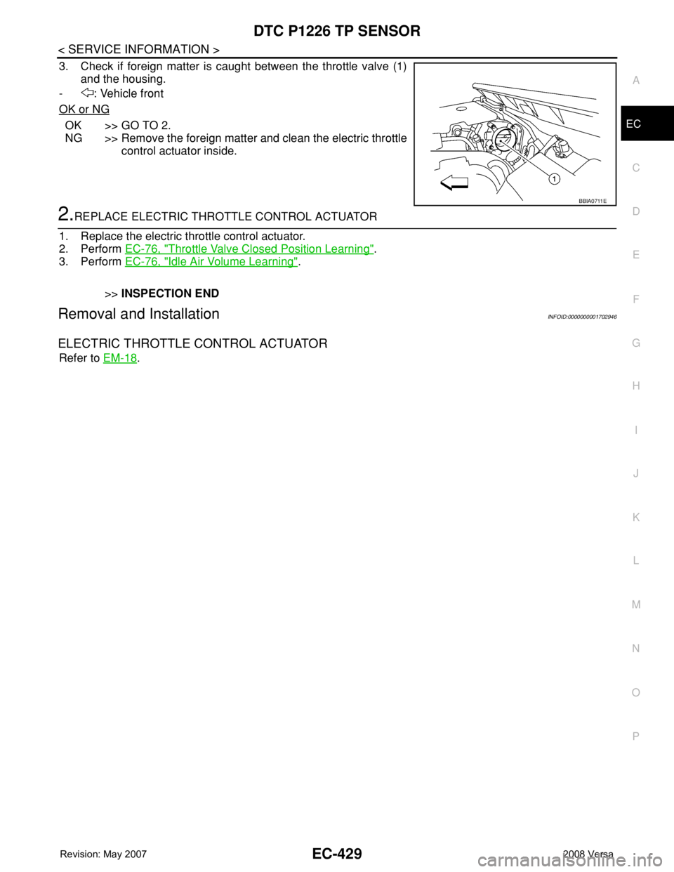
3. Check if foreign matter is caught between the throttle valve (1)
and the housing.
- : Vehicle front
OK or NG
OK >> GO TO 2.
NG >> Remove the foreign matter and clean the electric throttle
control actuator inside.
2.REPLACE ELECTRIC THROTTLE CONTROL ACTUATOR
1. Replace the electric throttle control actuator.
2. Perform EC-76, "
Throttle Valve Closed Position Learning".
3. Perform EC-76, "
Idle Air Volume Learning".
>>INSPECTION END
Removal and InstallationINFOID:0000000001702946
ELECTRIC THROTTLE CONTROL ACTUATOR
Refer to EM-18.
BBIA0711E