2008 NISSAN TIIDA ground
[x] Cancel search: groundPage 2673 of 2771
SIDE CURTAIN AIR BAG MODULE
SRS-39
< ON-VEHICLE REPAIR >
C
D
E
F
G
I
J
K
L
MA
B
SRS
N
O
P
SIDE CURTAIN AIR BAG MODULE
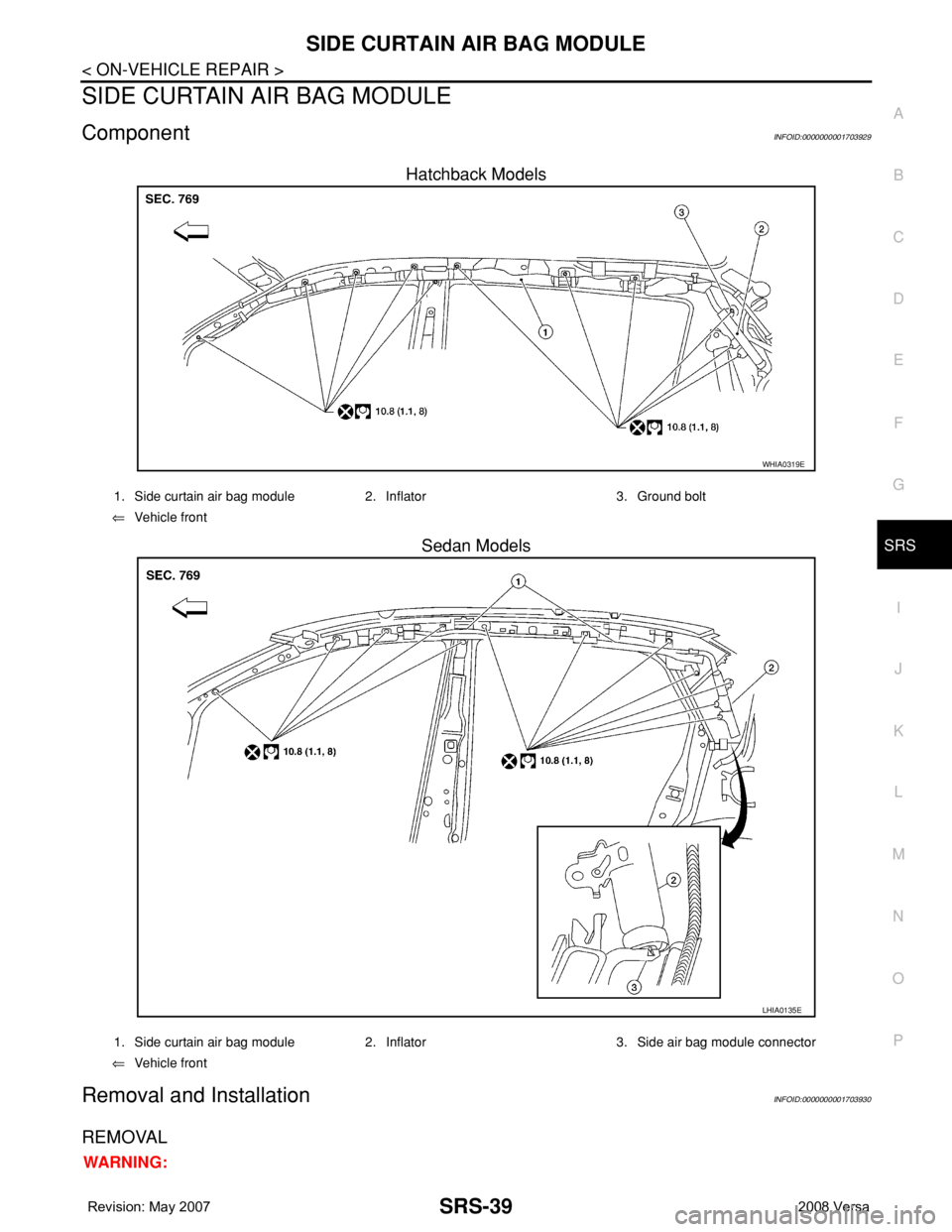
ComponentINFOID:0000000001703929
Hatchback Models
Sedan Models
Removal and InstallationINFOID:0000000001703930
REMOVAL
WARNING:
WHIA0319E
1. Side curtain air bag module 2. Inflator 3. Ground bolt
⇐Vehicle front
LHIA0135E
1. Side curtain air bag module 2. Inflator 3. Side air bag module connector
⇐Vehicle front
Page 2678 of 2771
SRS-44
< ON-VEHICLE REPAIR >
DIAGNOSIS SENSOR UNIT
DIAGNOSIS SENSOR UNIT
Removal and InstallationINFOID:0000000001703934
REMOVAL
WARNING:
Before disconnecting diagnosis sensor unit harness connector(s), be sure to disconnect harness con-
nectors from air bag modules and front seat belt pre-tensioner to prevent deployment by static elec-
tricity.
CAUTION:
• Before servicing the SRS, turn the ignition switch OFF, disconnect both battery cables and wait at
least 3 minutes.
• Do not disassemble diagnosis sensor unit.
• Do not use old bolts; replace with new bolts.
• Replace the diagnosis sensor unit if it has been dropped or sustained an impact.
• Check diagnosis sensor unit bracket to make sure it is free of deformities, dents, cracks or rust. If it
shows any visible signs of damage, replace with new one.
• The diagnosis sensor unit must always be installed with the arrow mark "⇐" pointing toward the
front of the vehicle for proper operation.
1. Disconnect the negative and positive battery cables, then wait at least 3 minutes.
2. Disconnect the harness connectors for each air bag module and seat belt pre-tensioner. Refer to SRS-33
,
SRS-38
, SRS-39, SRS-43.
3. Remove center console assembly. Refer to IP-10
.
4. Disconnect diagnosis sensor unit connectors.
5. Remove the bolts and the ground bolt, then remove the diagnosis sensor unit.
INSTALLATION
Installation is in the reverse order of removal.
• The diagnosis sensor unit must always be installed with the arrow mark "⇐" pointing toward the front of the
vehicle.
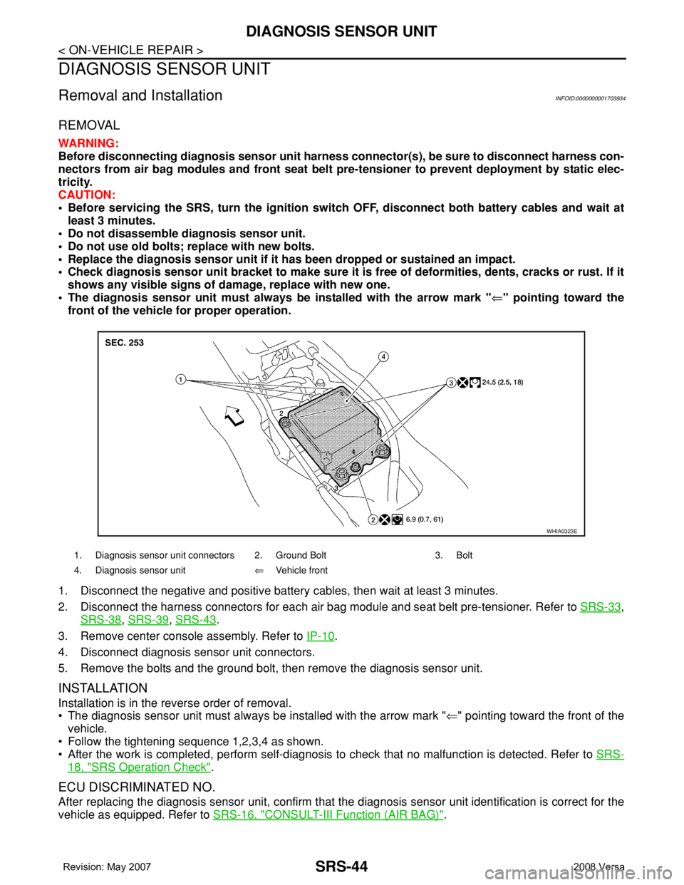
• Follow the tightening sequence 1,2,3,4 as shown.
• After the work is completed, perform self-diagnosis to check that no malfunction is detected. Refer to SRS-
18, "SRS Operation Check".
ECU DISCRIMINATED NO.
After replacing the diagnosis sensor unit, confirm that the diagnosis sensor unit identification is correct for the
vehicle as equipped. Refer to SRS-16, "
CONSULT-III Function (AIR BAG)".
1. Diagnosis sensor unit connectors 2. Ground Bolt 3. Bolt
4. Diagnosis sensor unit⇐Vehicle front
WHIA0323E
Page 2686 of 2771
![NISSAN TIIDA 2008 Service Repair Manual PRECAUTIONS
STC-3
< SERVICE INFORMATION >[EPS]
C
D
E
F
H
I
J
K
L
MA
B
STC
N
O
P
• Check any possible causes by interviewing the symptom and it’s condition from the customer if any
malfunction, suc](/manual-img/5/57399/w960_57399-2685.png "NISSAN TIIDA 2008 Service Repair Manual PRECAUTIONS
STC-3
< SERVICE INFORMATION >[EPS]
C
D
E
F
H
I
J
K
L
MA
B
STC
N
O
P
• Check any possible causes by interviewing the symptom and it’s condition from the customer if any
malfunction, suc")
PRECAUTIONS
STC-3
< SERVICE INFORMATION >[EPS]
C
D
E
F
H
I
J
K
L
MA
B
STC
N
O
P
• Check any possible causes by interviewing the symptom and it’s condition from the customer if any
malfunction, such as EPS warning lamp turns ON, occurs.
• Check if air pressure and size of tires are proper, the specified part is used for the steering wheel,
and control unit is genuine part.
• Check if the connection of steering column assembly and steering gear assembly is proper (there is
not looseness of mounting bolts, damage of rods, boots or sealants, and leakage of grease, etc).
• Check if the wheel alignment is adjusted properly.
• Check if there is any damage or modification to suspension or body resulting in increased weight or
altered ground clearance.
• Check if installation conditions of each link and suspension are proper.
• Check if the battery voltage is proper
• Check connection conditions of each connector are proper.
• Before connecting or disconnecting the EPS control unit har-
ness connector, turn ignition switch “OFF” and disconnect
battery ground cable. Because battery voltage is applied to
EPS control unit even if ignition switch is turned “OFF”.
• When connecting or disconnecting pin connectors into or
from EPS control unit, take care not to damage pin terminals
(bend or break).
When connecting pin connectors, make sure that there are no
bends or breaks on EPS control unit pin terminal.
• Before replacing EPS control unit, perform EPS control unit
input/output signal inspection and make sure whether EPS
control unit functions properly or not. Refer to STC-9, "
EPS
Control Unit Input/Output Signal Reference Value".
SEF289H
SEF291H
SDIA1848E
Page 2694 of 2771
![NISSAN TIIDA 2008 Service Repair Manual TROUBLE DIAGNOSIS
STC-11
< SERVICE INFORMATION >[EPS]
C
D
E
F
H
I
J
K
L
MA
B
STC
N
O
P
Data are reference values and are measured between each terminal and ground.
CAUTION:
When using a circuit tester](/manual-img/5/57399/w960_57399-2693.png "NISSAN TIIDA 2008 Service Repair Manual TROUBLE DIAGNOSIS
STC-11
< SERVICE INFORMATION >[EPS]
C
D
E
F
H
I
J
K
L
MA
B
STC
N
O
P
Data are reference values and are measured between each terminal and ground.
CAUTION:
When using a circuit tester")
TROUBLE DIAGNOSIS
STC-11
< SERVICE INFORMATION >[EPS]
C
D
E
F
H
I
J
K
L
MA
B
STC
N
O
P
Data are reference values and are measured between each terminal and ground.
CAUTION:
When using a circuit tester to measure voltage for inspection, be sure not to extend forcibly any connector terminals.
CONSULT-III Function (EPS)INFOID:0000000001703881
FUNCTION
CONSULT-III can display each diagnostic item using the diagnostic test modes shown following.
SELF-DIAG RESULTS MODE
Display Item List
Te r m i n a lWire
colorItem Condition Data (Approx.)
4 V Torque sensor sub Engine runningSteering wheel: Not steering
(There in no steering force)2.5 V
Steering wheel: Steering1.7 V – 3.3 V
(The value is changed accord-
ing to steering left or right)
5 BR Torque sensor power supplyIgnition switch: ON 8 V
Ignition switch: OFF 0 V
6 G Torque sensor main Engine runningSteering wheel: Not steering
(There is no steering force)2.5 V
Steering wheel: Steering1.7 V – 3.3 V
(The value is changed accord-
ing to steering left or right)
7 R Torque sensor ground Always 0 V
9 L CAN-H — —
10 O Power supplyIgnition switch: ON Battery voltage
Ignition switch: OFF 0 V
16 P CAN-L — —
17 R Power supply (Memory back-up)Ignition switch: ON Battery voltage
Ignition switch: OFF Battery voltage
18 B Ground Always 0 V
19 — Motor (+) — —
20 — Motor (–) — —
Diagnostic test mode Function Reference page
Self-diagnostic results • Self-diagnostic results can be read and erased quickly."SELF-DIAG
RESULTS
MODE"
Data monitor • Input/Output data in the EPS control unit can be read."DATA MONI-
TOR"
CAN diagnostic support monitor • The results of transmit/receive diagnosis of CAN communication can be read.LAN-6
ECU part number • EPS control unit part number can be read."EPS CON-
TROL UNIT
PART NUM-
BER"
Page 2696 of 2771
![NISSAN TIIDA 2008 Service Repair Manual TROUBLE DIAGNOSIS
STC-13
< SERVICE INFORMATION >[EPS]
C
D
E
F
H
I
J
K
L
MA
B
STC
N
O
P
Symptom ChartINFOID:0000000001703882
If EPS warning lamp turns ON, perform self-diagnosis. Refer to STC-11, "](/manual-img/5/57399/w960_57399-2695.png "NISSAN TIIDA 2008 Service Repair Manual TROUBLE DIAGNOSIS
STC-13
< SERVICE INFORMATION >[EPS]
C
D
E
F
H
I
J
K
L
MA
B
STC
N
O
P
Symptom ChartINFOID:0000000001703882
If EPS warning lamp turns ON, perform self-diagnosis. Refer to STC-11, \"")
TROUBLE DIAGNOSIS
STC-13
< SERVICE INFORMATION >[EPS]
C
D
E
F
H
I
J
K
L
MA
B
STC
N
O
P
Symptom ChartINFOID:0000000001703882
If EPS warning lamp turns ON, perform self-diagnosis. Refer to STC-11, "CONSULT-III Function (EPS)" .
Symptom Condition Check item Reference page
EPS warning lamp does not turn ON when ig-
nition switch to “ON”.
(EPS warning lamp check)Ignition switch: ONCAN communication line
STC-21
Combination meter
EPS warning lamp does not turn OFF for sev-
eral seconds after starting the engineEngine runningCAN communication line
STC-21
Power supply and ground for
EPS control unit
Torque sensor
EPS motor
Vehicle speed signal
Engine status signal
Combination meter
Steering wheel turning force is heavy or light,
while driving• While driving
• Steering wheel turningCAN communication line
STC-22
Vehicle speed signal
Engine status signal
EPS motor
Steering wheel turning force
(Mechanical malfunction)
Unbalance steering wheel turning force and
return between right and left, while driving• While driving
• Steering wheel turningWheel alignment
STC-23
Steering wheel turning force
(Mechanical malfunction)
Unbalance steering wheel turning force,
while driving (Torque variation)• While driving
• Steering wheel turningSteering column intermediate
shaft installation condition
STC-24
Steering wheel turning force
(Mechanical malfunction)
Page 2697 of 2771
![NISSAN TIIDA 2008 Service Repair Manual STC-14
< SERVICE INFORMATION >[EPS]
TROUBLE DIAGNOSIS FOR SYSTEM
TROUBLE DIAGNOSIS FOR SYSTEM
DTC C1601 BATTERY VOLTINFOID:0000000001703883
CONSULT-III REFERENCE VALUE IN DATA MONITOR MODE
Data are re](/manual-img/5/57399/w960_57399-2696.png "NISSAN TIIDA 2008 Service Repair Manual STC-14
< SERVICE INFORMATION >[EPS]
TROUBLE DIAGNOSIS FOR SYSTEM
TROUBLE DIAGNOSIS FOR SYSTEM
DTC C1601 BATTERY VOLTINFOID:0000000001703883
CONSULT-III REFERENCE VALUE IN DATA MONITOR MODE
Data are re")
STC-14
< SERVICE INFORMATION >[EPS]
TROUBLE DIAGNOSIS FOR SYSTEM
TROUBLE DIAGNOSIS FOR SYSTEM
DTC C1601 BATTERY VOLTINFOID:0000000001703883
CONSULT-III REFERENCE VALUE IN DATA MONITOR MODE
Data are reference value.
TERMINALS AND REFERENCE VALUES FOR EPS CONTROL UNIT
Refer to STC-10, "EPS Terminal and Reference Value".
DIAGNOSTIC PROCEDURE
1.CHECK EPS CONTROL UNIT POWER SUPPLY CIRCUIT
1. Turn ignition switch “OFF”.
2. Disconnect EPS control unit harness connector.
3. Turn ignition switch “ON”. (Do not start engine.)
4. Check voltage between EPS control unit harness connector (A)
terminals and ground.
5. Turn ignition switch “OFF”.
6. Check voltage between EPS control unit harness connector (A)
terminals and ground.
7. Connect EPS control unit harness connector.
OK or NG
OK >> GO TO 2.
NG >> Check the following. If any items are damaged, repair or replace damaged parts.
• 60 A fusible link (No. m, located in the fuse and fusible link block). Refer to PG-3
.
• 10 A fuse [No. 2, located in the fuse block (J/B)]. Refer to PG-3
.
• Harness for short or open between battery and EPS control unit harness connector M54 termi-
nal 17.
• Harness for short or open between ignition switch and EPS control unit harness connector M53
terminal 10.
2.CHECK EPS CONTROL UNIT GROUND CIRCUIT
1. Turn ignition switch “OFF”.
2. Disconnect EPS control unit harness connector.
Monitor item (Unit) Content Condition Display value
MOTOR VOL (V) Power supply voltage for EPS control unit Ignition switch: ON Battery voltage
Connector Terminal Voltage
M53 10 – Ground Battery voltage
M54 17 – Ground Battery voltage
SGIA1626E
Connector Terminal Voltage
M53 10 – Ground Approx. 0 V
M54 17 – Ground Battery voltage
SGIA1627E
Page 2698 of 2771
![NISSAN TIIDA 2008 Service Repair Manual TROUBLE DIAGNOSIS FOR SYSTEM
STC-15
< SERVICE INFORMATION >[EPS]
C
D
E
F
H
I
J
K
L
MA
B
STC
N
O
P
3. Check continuity between EPS control unit harness connector
(A) terminal and ground.
Also check har](/manual-img/5/57399/w960_57399-2697.png "NISSAN TIIDA 2008 Service Repair Manual TROUBLE DIAGNOSIS FOR SYSTEM
STC-15
< SERVICE INFORMATION >[EPS]
C
D
E
F
H
I
J
K
L
MA
B
STC
N
O
P
3. Check continuity between EPS control unit harness connector
(A) terminal and ground.
Also check har")
TROUBLE DIAGNOSIS FOR SYSTEM
STC-15
< SERVICE INFORMATION >[EPS]
C
D
E
F
H
I
J
K
L
MA
B
STC
N
O
P
3. Check continuity between EPS control unit harness connector
(A) terminal and ground.
Also check harness for short to power.
4. Connect EPS control unit harness connector.
OK or NG
OK >> GO TO 3.
NG >> Repair open circuit or short to ground or short to power
in harness or connectors.
3.CHECK DTC
Start engine.
Does EPS warning lamp turn OFF?
YES >>INSPECTION END
NO >> Perform self-diagnosis, repair or replace damaged parts. Refer to STC-11, "
CONSULT-III Func-
tion (EPS)".
DTC C1604 TORQUE SENSORINFOID:0000000001703884
CONSULT-III REFERENCE VALUE IN DATA MONITOR MODE
Data are reference value.
*: In the front of the value, “L” is displayed at steering left and “R” is displayed at steering right.
TERMINALS AND REFERENCE VALUES FOR EPS CONTROL UNIT
Refer to STC-10, "EPS Terminal and Reference Value".
DIAGNOSTIC PROCEDURE
1.CHECK TORQUE SENSOR SIGNAL
With CONSULT-III
1. Start engine.
2. Select “DATA MONITOR” mode for “EPS” with CONSULT-III.
3. Check the value of “TORQUE SENSOR”. Refer to STC-9, "
EPS Control Unit Input/Output Signal Refer-
ence Value".
Without CONSULT-III1. Start engine.
2. Check voltage between EPS control unit harness connector M53 terminals 4, 5, 6, 7 and ground. Refer to
STC-10, "
EPS Terminal and Reference Value".
OK or NG
OK >> GO TO 3.
NG >> GO TO 2.
2.CHECK HARNESS AND CONNECTOR
1. Turn ignition switch “OFF”.
2. Disconnect EPS control unit harness connector and torque sensor harness connector.
Connector Terminal Continuity
M54 18 Yes
SGIA1628E
Monitor item (Unit) Content Condition Display value
TORQUE SENSOR (Nm) Steering wheel turning force Engine runningSteering wheel: Not steering
(There is no steering force)0.00 Nm
Steering wheel: Steering0 – 8.19 Nm*
(The value is changed
according to steering
left or right)
Page 2699 of 2771
![NISSAN TIIDA 2008 Service Repair Manual STC-16
< SERVICE INFORMATION >[EPS]
TROUBLE DIAGNOSIS FOR SYSTEM
3. Check continuity between EPS control unit harness connector
(A) M53 terminals 4, 5, 6, 7 and torque sensor harness connec-
tor (B) M](/manual-img/5/57399/w960_57399-2698.png "NISSAN TIIDA 2008 Service Repair Manual STC-16
< SERVICE INFORMATION >[EPS]
TROUBLE DIAGNOSIS FOR SYSTEM
3. Check continuity between EPS control unit harness connector
(A) M53 terminals 4, 5, 6, 7 and torque sensor harness connec-
tor (B) M")
STC-16
< SERVICE INFORMATION >[EPS]
TROUBLE DIAGNOSIS FOR SYSTEM
3. Check continuity between EPS control unit harness connector
(A) M53 terminals 4, 5, 6, 7 and torque sensor harness connec-
tor (B) M63 terminals 1, 2, 3, 4.
Also check harness for short to ground and short to power.
4. Connect EPS control unit harness connector and torque sensor harness connector.
OK or NG
OK >> GO TO 3.
NG >> Repair or replace damaged parts.
3.CHECK EPS CONTROL UNIT
Check EPS control unit input/output signal. Refer to STC-9, "
EPS Control Unit Input/Output Signal Reference
Va l u e".
OK or NG
OK >> GO TO 4.
NG >> Check EPS control unit pin terminals for damage or loose connection with harness connector. If
any items are damaged, repair or replace damaged parts.
4.CHECK DTC
Perform the self-diagnosis, after driving the vehicle for a while.
OK or NG
OK >>INSPECTION END
NG >> Torque sensor is malfunctioning. Replace steering column assembly. Refer to PS-9, "
Removal
and Installation".
DTC C1606 EPS MOTORINFOID:0000000001703885
CONSULT-III REFERENCE VALUE IN DATA MONITOR MODE
Data are reference value.
* : Almost in accordance with the value of “MOTOR SIG”. It is not a malfunction though these values are not accorded when steering
quickly.
TERMINALS AND REFERENCE VALUES FOR EPS CONTROL UNIT
Refer to STC-10, "EPS Terminal and Reference Value".
DIAGNOSTIC PROCEDURE
1.CHECK EPS MOTOR SIGNAL
Terminal Continuity
4 – 3
Ye s 5 – 2
6 – 1
7 – 4
SGIA1629E
Monitor item (Unit) Content Condition Display value
MOTOR SIG (A)Command current to EPS
motorEngine runningSteering wheel: Not steering
(There is no steering force)0.00 A
Steering wheel: Steering0 – 65.00 A
(The value is changed
according to steering left
or right)
MOTOR CURRENT (A)Consumption current of
EPS motorEngine runningSteering wheel: Not steering
(There is no steering force)0.00 A
Steering wheel: Steering0 – 65.00 A*
(The value is changed
according to steering left
or right)