2008 NISSAN TIIDA ground
[x] Cancel search: groundPage 2704 of 2771
![NISSAN TIIDA 2008 Service Repair Manual TROUBLE DIAGNOSIS FOR SYMPTOMS
STC-21
< SERVICE INFORMATION >[EPS]
C
D
E
F
H
I
J
K
L
MA
B
STC
N
O
P
TROUBLE DIAGNOSIS FOR SYMPTOMS
EPS Warning Lamp Does Not Turn ONINFOID:0000000001703892
SYMPTOM:
EPS](/manual-img/5/57399/w960_57399-2703.png "NISSAN TIIDA 2008 Service Repair Manual TROUBLE DIAGNOSIS FOR SYMPTOMS
STC-21
< SERVICE INFORMATION >[EPS]
C
D
E
F
H
I
J
K
L
MA
B
STC
N
O
P
TROUBLE DIAGNOSIS FOR SYMPTOMS
EPS Warning Lamp Does Not Turn ONINFOID:0000000001703892
SYMPTOM:
EPS")
TROUBLE DIAGNOSIS FOR SYMPTOMS
STC-21
< SERVICE INFORMATION >[EPS]
C
D
E
F
H
I
J
K
L
MA
B
STC
N
O
P
TROUBLE DIAGNOSIS FOR SYMPTOMS
EPS Warning Lamp Does Not Turn ONINFOID:0000000001703892
SYMPTOM:
EPS warning lamp does not turn ON when ignition switch to “ON”.
DIAGNOSTIC PROCEDURE
1.CHECK SYSTEM FOR CAN COMMUNICATION LINE
Perform self-diagnosis. Refer to STC-11, "
CONSULT-III Function (EPS)" .
Is the
“CAN COMM CIRCUIT [U1000]” displayed?
YES >> Perform trouble diagnosis for CAN communication line. Refer to STC-19, "DTC U1000 CAN
COMM CIRCUIT" .
NO >> GO TO 2.
2.CHECK EPS CONTROL UNIT
Check EPS control unit input/output signal. Refer to STC-9, "
EPS Control Unit Input/Output Signal Reference
Va l u e" .
OK or NG
OK >> GO TO 3.
NG >> Check EPS control unit pin terminals for damage or loose connection with harness connector. If
any items are damaged, repair or replace damaged parts.
3.SYMPTOM CHECK
Check again.
OK or NG
OK >>INSPECTION END
NG >> Replace combination meter. Refer to DI-20, "
Removal and Installation" .
EPS Warning Lamp Does Not Turn OFFINFOID:0000000001703893
SYMPTOM:
EPS warning lamp does not turn OFF for several seconds after starting the engine.
DIAGNOSTIC PROCEDURE
1.CHECK SELF-DIAGNOSTIC RESULTS
Perform self-diagnosis. Refer to STC-11, "
CONSULT-III Function (EPS)" .
Is any malfunction detected by self-diagnosis?
YES >> Check the malfunctioning system.
NO >> GO TO 2.
2.CHECK EPS CONTROL UNIT POWER SUPPLY CIRCUIT
1. Turn ignition switch “OFF”.
2. Disconnect EPS control unit harness connector.
3. Turn ignition switch “ON”. (Do not start engine.)
4. Check voltage between EPS control unit harness connector (A)
terminals and ground.
Connector Terminal Voltage
M53 10 – Ground Battery voltage
M54 17 – Ground Battery voltage
SGIA1626E
Page 2705 of 2771
![NISSAN TIIDA 2008 Service Repair Manual STC-22
< SERVICE INFORMATION >[EPS]
TROUBLE DIAGNOSIS FOR SYMPTOMS
5. Turn ignition switch “OFF”.
6. Check voltage between EPS control unit harness connector (A)
terminals and ground.
7. Connect E](/manual-img/5/57399/w960_57399-2704.png "NISSAN TIIDA 2008 Service Repair Manual STC-22
< SERVICE INFORMATION >[EPS]
TROUBLE DIAGNOSIS FOR SYMPTOMS
5. Turn ignition switch “OFF”.
6. Check voltage between EPS control unit harness connector (A)
terminals and ground.
7. Connect E")
STC-22
< SERVICE INFORMATION >[EPS]
TROUBLE DIAGNOSIS FOR SYMPTOMS
5. Turn ignition switch “OFF”.
6. Check voltage between EPS control unit harness connector (A)
terminals and ground.
7. Connect EPS control unit harness connector.
OK or NG
OK >> GO TO 3.
NG >> Check the following. If any items are damaged, repair or replace damaged parts.
• 60 A fusible link (No. m, located in the fuse and fusible link block). Refer to PG-3
.
• 10 A fuse [No. 2, located in the fuse block (J/B)]. Refer to PG-3
.
• Harness for short or open between battery and EPS control unit harness connector M54 termi-
nal 17.
• Harness for short or open between ignition switch and EPS control unit harness connector M53
terminal 10.
3.CHECK EPS CONTROL UNIT GROUND CIRCUIT
1. Turn ignition switch “OFF”.
2. Disconnect EPS control unit harness connector.
3. Check continuity between EPS control unit harness connector
(A) terminal and ground.
Also check harness for short to power.
4. Connect EPS control unit harness connector.
OK or NG
OK >> GO TO 4.
NG >> Repair open circuit or short to ground or short to power
in harness or connectors.
4.CHECK EPS CONTROL UNIT
Check EPS control unit input/output signal. Refer to STC-9, "
EPS Control Unit Input/Output Signal Reference
Va l u e" .
OK or NG
OK >> GO TO 5.
NG >> Check EPS control unit pin terminals for damage or loose connection with harness connector. If
any items are damaged, repair or replace damaged parts.
5.SYMPTOM CHECK
Check again.
OK or NG
OK >>INSPECTION END
NG >> Replace combination meter. Refer to DI-20, "
Removal and Installation" .
Steering Wheel Turning Force Is Heavy or LightINFOID:0000000001703894
SYMPTOM:
Steering wheel turning force is heavy or light, while driving.
DIAGNOSTIC PROCEDURE
1.CHECK SYSTEM FOR CAN COMMUNICATION LINE
Perform self-diagnosis. Refer to STC-11, "
CONSULT-III Function (EPS)" .
Connector Terminal Voltage
M53 10 – Ground Approx. 0 V
M54 17 – Ground Battery voltage
SGIA1627E
Connector Terminal Continuity
M54 18 YES
SGIA1628E
Page 2728 of 2771
WT-20
< SERVICE INFORMATION >
TROUBLE DIAGNOSIS FOR SYMPTOMS
TROUBLE DIAGNOSIS FOR SYMPTOMS
Low Tire Pressure Warning Lamp Does Not Come On When Ignition Switch Is Turned
On
INFOID:0000000001703767
DIAGNOSTIC PROCEDURE
1.SELF-DIAGNOSTIC RESULT CHECK
Using CONSULT-III, check display contents in self-diagnostic results.
Is "CAN COMM CIRCUIT" displayed in the self-diagnosis display items?
YES >> Malfunction in CAN communication system. GO TO LAN-12, "CAN Diagnosis with CONSULT-
III".
NO >> GO TO 2.
2.CHECK COMBINATION METER
Check combination meter operation. Refer to DI-11, "
Self-Diagnosis Mode of Combination Meter".
Inspection results OK?
OK >> GO TO 3.
NG >> Replace combination meter. Refer to IP-11, "
Removal and Installation".
3.CHECK LOW TIRE PRESSURE WARNING LAMP
Disconnect BCM harness connector.
Does the low tire pressure warning lamp activate?
YES >> Replace BCM. Refer to BCS-18, "Removal and Installation of BCM".
NO >> Check combination meter operation. Refer to DI-11, "
Self-Diagnosis Mode of Combination
Meter".
Low Tire Pressure Warning Lamp Stays On When Ignition Switch Is Turned On
INFOID:0000000001703768
DIAGNOSTIC PROCEDURE
1.CHECK BCM CONNECTORS
1. Turn ignition switch OFF.
2. Disconnect BCM harness connectors M18 and M20.
3. Check terminals for damage or loose connections.
Inspection results OK?
OK >> GO TO 2.
NG >> Repair or replace damaged parts.
2.CHECK BCM POWER SUPPLY CIRCUIT (BAT)
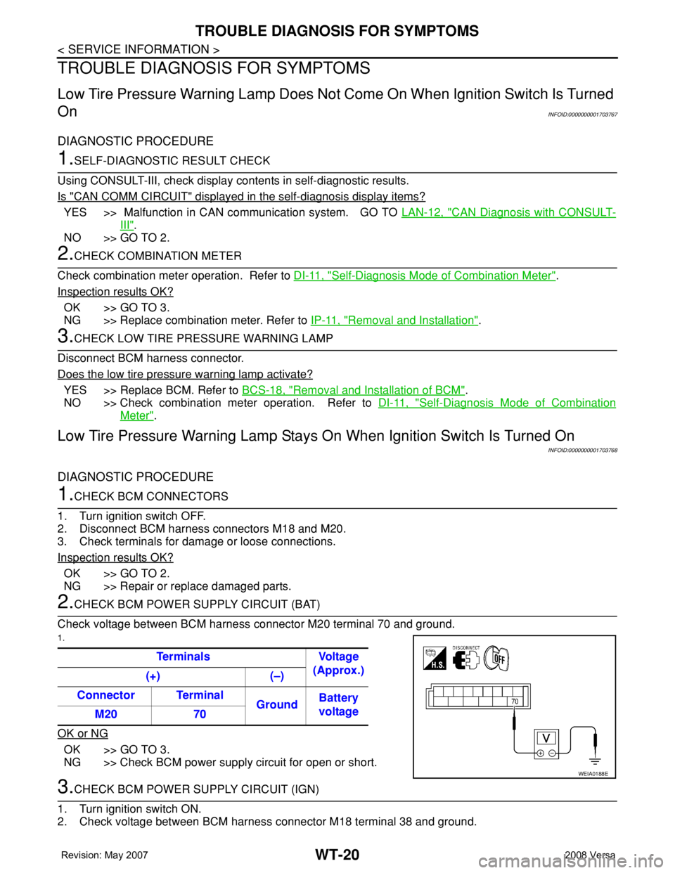
Check voltage between BCM harness connector M20 terminal 70 and ground.
1.
OK or NG
OK >> GO TO 3.
NG >> Check BCM power supply circuit for open or short.
3.CHECK BCM POWER SUPPLY CIRCUIT (IGN)
1. Turn ignition switch ON.
2. Check voltage between BCM harness connector M18 terminal 38 and ground.Terminals Voltage
(Approx.)
(+) (–)
Connector Terminal
GroundBattery
voltage
M20 70
WEIA0188E
Page 2729 of 2771
TROUBLE DIAGNOSIS FOR SYMPTOMS
WT-21
< SERVICE INFORMATION >
C
D
F
G
H
I
J
K
L
MA
B
WT
N
O
P
OK or NG
OK >> GO TO 4.
NG >> Check BCM power supply circuit for open or short.
4.CHECK BCM GROUND CIRCUIT
1. Turn ignition switch OFF.
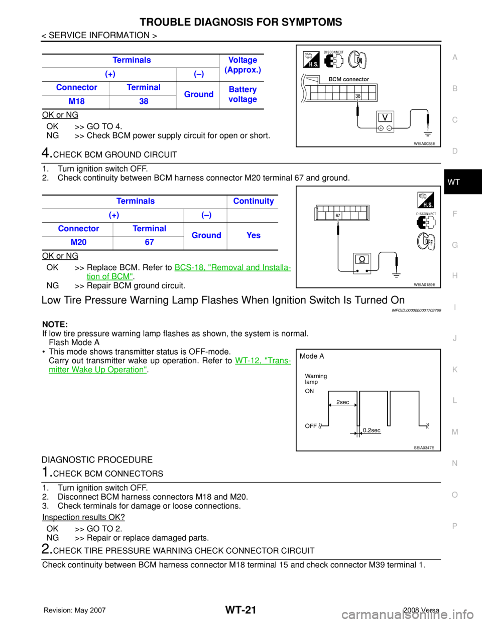
2. Check continuity between BCM harness connector M20 terminal 67 and ground.
OK or NG
OK >> Replace BCM. Refer to BCS-18, "Removal and Installa-
tion of BCM".
NG >> Repair BCM ground circuit.
Low Tire Pressure Warning Lamp Flashes When Ignition Switch Is Turned On
INFOID:0000000001703769
NOTE:
If low tire pressure warning lamp flashes as shown, the system is normal.
Flash Mode A
• This mode shows transmitter status is OFF-mode.
Carry out transmitter wake up operation. Refer to WT-12, "
Trans-
mitter Wake Up Operation".
DIAGNOSTIC PROCEDURE
1.CHECK BCM CONNECTORS
1. Turn ignition switch OFF.
2. Disconnect BCM harness connectors M18 and M20.
3. Check terminals for damage or loose connections.
Inspection results OK?
OK >> GO TO 2.
NG >> Repair or replace damaged parts.
2.CHECK TIRE PRESSURE WARNING CHECK CONNECTOR CIRCUIT
Check continuity between BCM harness connector M18 terminal 15 and check connector M39 terminal 1. Terminals Voltage
(Approx.)
(+) (–)
Connector Terminal
GroundBattery
voltage
M18 38
WEIA0038E
Terminals Continuity
(+) (–)
Connector Terminal
Ground Yes
M20 67
WEIA0189E
SEIA0347E
Page 2730 of 2771
WT-22
< SERVICE INFORMATION >
TROUBLE DIAGNOSIS FOR SYMPTOMS
OK or NG
OK >> Replace BCM. Refer to BCS-18, "Removal and Installa-
tion of BCM".
NG >> Repair or replace harness connector.
Hazard Warning Lamps Flash When Ignition Switch Is Turned OnINFOID:0000000001703770
DIAGNOSTIC PROCEDURE
1.CHECK BCM GROUND CIRCUIT
1. Turn ignition switch OFF.
2. Disconnect BCM harness connector M20.
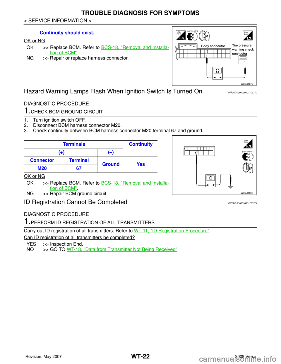
3. Check continuity between BCM harness connector M20 terminal 67 and ground.
OK or NG
OK >> Replace BCM. Refer to BCS-18, "Removal and Installa-
tion of BCM".
NG >> Repair BCM ground circuit.
ID Registration Cannot Be CompletedINFOID:0000000001703771
DIAGNOSTIC PROCEDURE
1.PERFORM ID REGISTRATION OF ALL TRANSMITTERS
Carry out ID registration of all transmitters. Refer to WT-11, "
ID Registration Procedure".
Can ID registration of all transmitters be completed?
YES >> Inspection End.
NO >> GO TO WT-18, "
Data from Transmitter Not Being Received". Continuity should exist.
WEIA0127E
Terminals Continuity
(+) (–)
Connector Terminal
Ground Yes
M20 67
WEIA0189E
Page 2737 of 2771

WW-4
< SERVICE INFORMATION >
FRONT WIPER AND WASHER SYSTEM
• to front wiper high relay (located in IPDM E/R), and
• to CPU (located in IPDM E/R),
• through 10A fuse [No. 6, located in fuse block (J/B)]
• to BCM terminal 38,
• through 15A fuse [No. 4, located in fuse block (J/B)]
• to combination switch terminal 14.
Ground is supplied
• to IPDM E/R terminals 39 and 59, and
• to front wiper motor terminal 2
• through grounds E15 and E24
• to BCM terminal 67, and
• to combination switch terminal 12
• through grounds M57 and M61.
LOW SPEED WIPER OPERATION
When the front wiper switch is in LO position, the BCM detects the low speed wiper ON signal by means of the
BCM wiper switch reading function.
The BCM sends a front wiper request signal (LO) through the CAN communication line
• from BCM terminals 39 and 40
• to IPDM E/R terminals 40 and 41.
When the IPDM E/R receives front wiper request signal (LO), it turns ON front wiper relay, located in IPDM E/
R, power is supplied
• through IPDM E/R terminal 33 and front wiper high relay and front wiper relay
• to front wiper motor terminal 3.
Ground is supplied
• to front wiper motor terminal 2
• through grounds E15 and E24.
With power and ground is supplied, front wiper motor operates at low speed.
HIGH SPEED WIPER OPERATION
When the front wiper switch is in HI position, the BCM detects a high speed wiper ON signal by means of the
BCM wiper switch reading function.
The BCM sends a front wiper request signal (HI) through the CAN communication line
• from BCM terminals 39 and 40
• to IPDM E/R terminals 40 and 41.
When the IPDM E/R receives front wiper request signal (HI), it turns ON front wiper relay and front wiper high
relay, located in IPDM E/R, power is supplied
• through IPDM E/R terminal 32
• to front wiper motor terminal 5.
Ground is supplied
• to front wiper motor terminal 2
• through grounds E15 and E24.
With power and ground is supplied, front wiper motor operates at high speed.
INTERMITTENT OPERATION
Wiper intermittent operation delay interval is determined from the intermittent wiper dial position inputs. During
each intermittent operation delay interval, the BCM sends a front wiper request signal to the IPDM E/R to
operate the wipers.
When the ignition switch is in the ON or START position, and the front wiper switch is turned to the intermittent
position, the BCM detects a front wiper (intermittent) ON signal by means of the BCM wiper switch reading
function.
BCM then sends front wiper (intermittent) request signal through the CAN communication lines
• from BCM terminals 39 and 40
• to IPDM E/R terminals 40 and 41.
When BCM determines that combination switch status is front wiper intermittent ON, it performs the following
operations.
• BCM detects ON/OFF status of intermittent wiper dial position
• BCM calculates operation interval from wiper dial position.
• BCM sends a front wiper request signal (INT) to IPDM E/R at calculated operation interval.
When IPDM E/R receives the front wiper request signal (INT), it supplies ground to energize the front wiper
relay. It then sends auto-stop signal to the BCM and conducts intermittent front wiper motor operation.
Page 2738 of 2771
FRONT WIPER AND WASHER SYSTEM
WW-5
< SERVICE INFORMATION >
C
D
E
F
G
H
I
J
L
MA
B
WW
N
O
P
AUTO STOP OPERATION
With wiper switch turned OFF, wiper motor will continue to operate until wiper arms reach windshield base.
When the wiper arms are not located at base of windshield with wiper switch OFF, ground is supplied
• from IPDM E/R terminal 33
• to front wiper motor terminal 3, in order to continue wiper motor operation at low speed.
When the wiper arms reach base of windshield, front wiper motor terminals 4 and 2 are connected, and
ground is supplied
• to IPDM E/R terminal 38
• through front wiper motor terminals 4 and 2, and
• through grounds E15 and E24.
Then the IPDM E/R sends auto stop operation signal to BCM with CAN communication line.
When the BCM receives auto-stop operation signal, BCM sends wiper stop signal to IPDM E/R with CAN com-
munication line.
IPDM E/R stops wiper motor. Wiper motor will then stop wiper arms at the STOP position.
WASHER OPERATION
When the wiper switch is in front wiper washer position, BCM detect front wiper washer signal by BCM combi-
nation switch reading function. Refer to BCS-3, "
System Description" .
Combination switch power is supplied• through combination switch terminal 14
• to washer motor terminal 1.
Ground is supplied• to front washer motor terminal 2
• through combination switch terminal 11, and
• through combination switch terminal 12
• through grounds M57 and M61.
With ground supplied, front washer motor is operated.
When the BCM detects that front washer motor has operated for 0.4 seconds or longer, BCM operates front
wiper motor for low speed.
When the BCM detects washer switch is OFF, low speed operation cycles approximately 2 times and stops.
MIST OPERATION
When the wiper switch is turned to the mist position, wiper low speed operation cycles once and then stops.
For additional information about wiper operation under this condition, refer to "LOW SPEED WIPER OPERA-
TION" .
If switch is held in mist position, low speed operation continues.
FAIL-SAFE FUNCTION
If an abnormality occurs in CAN communications, IPDM E/R holds the condition just before fail-safe status is
initiated until ignition switch is turned OFF. (If wipers were operating in LO just before the initiation of fail-safe
status, they continue to operate in LO until ignition switch is turned OFF.)
COMBINATION SWITCH READING FUNCTION
Refer to BCS-3, "System Description" .
CAN Communication System DescriptionINFOID:0000000001704537
Refer to LAN-6, "System Description".
Page 2743 of 2771

WW-10
< SERVICE INFORMATION >
FRONT WIPER AND WASHER SYSTEM
How to Proceed with Trouble Diagnosis
INFOID:0000000001704542
1. Confirm symptoms and customer complaint.
2. Understand operation description and function description. Refer to WW-3, "
System Description" .
3. Perform preliminary check. Refer to WW-10, "
Preliminary Check" .
4. Check symptom and repair or replace malfunctioning parts.
5. Does front wiper and washer operate normally? If YES, GO TO 6. If NO, GO TO 4.
6. Inspection End.
Preliminary CheckINFOID:0000000001704543
CHECK POWER SUPPLY AND GROUND CIRCUIT FOR BCM
Refer to BCS-15, "BCM Power Supply and Ground Circuit Inspection"
CONSULT-III Function (BCM)INFOID:0000000001704544
CONSULT-III can display each diagnostic item using the diagnostic test modes shown following.
WORK SUPPORT
Display Item List
DATA MONITOR
Display Item List
BCM diagnosis position Diagnosis mode Description
WIPERWORK SUPPORT Changes the setting for each function.
DATA MONITOR Displays BCM input data in real time.
ACTIVE TEST Device operation can be checked by applying a drive signal to device.
BCMSELF-DIAG RESULTS BCM performs self-diagnosis of CAN communication.
CAN DIAG SUPPORT MNTR The result of transmit/receive diagnosis of CAN communication can be read.
Item Description CONSULT-III Factory setting
WIPER SPEED
SETTINGVehicle speed sensing type wiper control mode can be changed in this mode.ON×
OFF —
ALL SIGNALS Monitors all the signals.
SELECTION FROM MENU Selects items and monitor them.
Monitor item Contents
IGN ON SW “ON/OFF”Displays “ignition switch ON (ON)/Other OFF or ACC (OFF)” status as judged from ignition
switch signal.
IGN SW CAN “ON/OFF”Displays “ignition switch ON (ON)/Other OFF or ACC (OFF)” status as judged from CAN com-
munication signal.
FR WIPER HI “ON/OFF” Displays “FRONT WIPER HI (ON)/Other (OFF)” status as judged from wiper switch signal.
FR WIPER LOW “ON/OFF” Displays “FRONT WIPER LOW (ON)/Other (OFF)” status as judged from wiper switch signal.
FR WIPER INT “ON/OFF” Displays “FRONT WIPER INT (ON)/Other (OFF)” status as judged from wiper switch signal.
FR WASHER SW “ON/OFF”Displays “FRONT WASHER Switch (ON)/Other (OFF)” status as judged from wiper switch sig-
nal.
INT VOLUME “1 - 7” Displays intermittent operation dial position setting (1 - 7) as judged from wiper switch signal.
FR WIPER STOP “ON/OFF” Displays “Stopped (ON)/Operating (OFF)” status as judged from auto-stop signal.
VEHICLE SPEED “km/h” Displays vehicle speed status as judged from vehicle speed signal.