2008 NISSAN TIIDA ground
[x] Cancel search: groundPage 1 of 2771

-1
QUICK REFERENCE INDEX
AGENERAL INFORMATIONGIGeneral Information
BENGINEEMEngine Mechanical
LUEngine Lubrication System
COEngine Cooling System
ECEngine Control System
FLFuel System
EXExhaust System
ACCAccelerator Control System
CTRANSMISSION/
TRANSAXLECLClutch System
MTManual Transaxle
ATAutomatic Transaxle
CVTCVT
DDRIVELINE/AXLEFAXFront Axle
RAXRear Axle
ESUSPENSIONFSUFront Suspension
RSURear Suspension
WTRoad Wheels & Tires
FBRAKESBRBrake System
PBParking Brake System
BRCBrake Control System
GSTEERINGPSPower Steering System
STCSteering Control System
HRESTRAINTSSBSeat Belts
SRSSupplemental Restraint System (SRS)
IBODYBLBody, Lock & Security System
GWGlasses, Window System & Mirrors
RFRoof
EIExterior & Interior
IPInstrument Panel
SESeat
JAIR CONDITIONERMTCManual Air Conditioner
KELECTRICALSCStarting & Charging System
LTLighting System
DIDriver Information System
WWWiper, Washer & Horn
BCSBody Control System
LANLAN System
AVAudio Visual, Navigation & Telephone System
ACSAuto Cruise Control System
PGPower Supply, Ground & Circuit Elements
LMAINTENANCEMAMaintenance
Edition: May 2007
Revision: May 2007
Publication No. SM8E-1C11U0
B
D
© 2007 NISSAN NORTH AMERICA, INC.
All rights reserved. No part of this Service Manual may be reproduced or stored in a retrieval system, or transmitted in any
form, or by any means, electronic, mechanical, photo-copying, recording or otherwise, without the prior written permission
of Nissan North America Inc.
A
C
E
F
G
H
I
J
K
L
M
Page 15 of 2771

AT-3
D
E
F
G
H
I
J
K
L
MA
B
AT
N
O
P N Wiring Diagram - AT - SSV/B ................................
140
Diagnosis Procedure .............................................141
Component Inspection ..........................................142
DTC P1760 OVERRUN CLUTCH SOLENOID
VALVE ..............................................................
144
Description ............................................................144
CONSULT-III Reference Value in Data Monitor
Mode .....................................................................
144
On Board Diagnosis Logic ....................................144
Possible Cause .....................................................144
DTC Confirmation Procedure ................................144
Wiring Diagram - AT - OVRCSV ...........................145
Diagnosis Procedure .............................................146
Component Inspection ..........................................147
DTC VEHICLE SPEED SENSOR MTR ............149
Description ............................................................149
CONSULT-III Reference Value in Data Monitor
Mode .....................................................................
149
On Board Diagnosis Logic ....................................149
Possible Cause .....................................................149
DTC Confirmation Procedure ................................149
Wiring Diagram - AT - VSSMTR ...........................150
Diagnosis Procedure .............................................151
DTC BATT/FLUID TEMP SEN (A/T FLUID
TEMP SENSOR CIRCUIT AND TCM POWER
SOURCE) .........................................................
152
Description ............................................................152
CONSULT-III Reference Value in Data Monitor
Mode .....................................................................
152
On Board Diagnosis Logic ....................................152
Possible Cause .....................................................152
DTC Confirmation Procedure ................................152
Wiring Diagram - AT - BA/FTS ..............................153
Diagnosis Procedure .............................................154
Component Inspection ..........................................156
DTC TURBINE REVOLUTION SENSOR .........158
Description ............................................................158
CONSULT-III Reference Value in Data Monitor
Mode .....................................................................
158
On Board Diagnosis Logic ....................................158
Possible Cause .....................................................158
DTC Confirmation Procedure ................................158
Wiring Diagram - AT - PT/SEN .............................159
Diagnosis Procedure .............................................160
CONTROL UNIT (RAM), CONTROL UNIT
(ROM) ...............................................................
163
Description ............................................................163
On Board Diagnosis Logic ....................................163
Possible Cause .....................................................163
DTC Confirmation Procedure ................................163
Diagnosis Procedure .............................................163
MAIN POWER SUPPLY AND GROUND CIR-
CUIT ..................................................................
164
Wiring Diagram - AT - MAIN .................................164
Diagnosis Procedure .............................................165
PNP, OD SWITCH AND CLOSED THROT-
TLE, WIDE OPEN THROTTLE POSITION
SIGNAL CIRCUIT ............................................
167
CONSULT-III Reference Value in Data Monitor
Mode ......................................................................
167
TCM Terminal and Reference Value .....................167
Diagnosis Procedure .............................................167
Component Inspection ...........................................171
SHIFT POSITION INDICATOR CIRCUIT ........172
Description .............................................................172
CONSULT-III Reference Value in Data Monitor
Mode ......................................................................
172
Diagnosis Procedure .............................................172
TROUBLE DIAGNOSIS FOR SYMPTOMS ....173
Wiring Diagram - AT - NONDTC ...........................173
OD OFF Indicator Lamp Does Not Come On ........176
Engine Cannot Be Started in "P" and "N" Position ..178
In "P" Position, Vehicle Moves Forward or Back-
ward When Pushed ...............................................
179
In "N" Position, Vehicle Moves ..............................179
Large Shock "N" → "R" Position ............................180
Vehicle Does Not Creep Backward in "R" Position ..181
Vehicle Does Not Creep Forward in "D", "2" or "1"
Position ..................................................................
182
Vehicle Cannot Be Started from D1 .......................183
A/T Does Not Shift: D1→ D2or Does Not Kick-
down: D
4→ D2 .......................................................185
A/T Does Not Shift: D2→ D3 ..................................186
A/T Does Not Shift: D3→ D4 ..................................188
A/T Does Not Perform Lock-up .............................189
A/T Does Not Hold Lock-up Condition ...................190
Lock-up Is Not Released .......................................191
Engine Speed Does Not Return to Idle (Light
Braking D
4→ D3) ...................................................192
A/T Does Not Shift: D4→ D3, When OD OFF ........193
A/T Does Not Shift: D3→ 22, When Selector Lever
"D" → "2" Position .................................................
194
A/T Does Not Shift: 22→ 11, When Selector Lever
"2" → "1" Position ..................................................
195
Vehicle Does Not Decelerate by Engine Brake .....197
TCM Self-Diagnosis Does Not Activate .................200
TRANSMISSION CONTROL MODULE ..........202
Removal and Installation .......................................202
SHIFT CONTROL SYSTEM ............................203
Control Device Removal and Installation ...............203
Control Device Disassembly and Assembly ..........206
Selector Lever Knob Removal and Installation ......206
Adjustment of A/T Position ....................................207
Checking of A/T Position .......................................207
A/T SHIFT LOCK SYSTEM .............................209
Description .............................................................209
Shift Lock System Parts Location ..........................209
Wiring Diagram - AT - SHIFT ................................210
Page 83 of 2771
TROUBLE DIAGNOSIS
AT-71
< SERVICE INFORMATION >
D
E
F
G
H
I
J
K
L
MA
B
AT
N
O
P
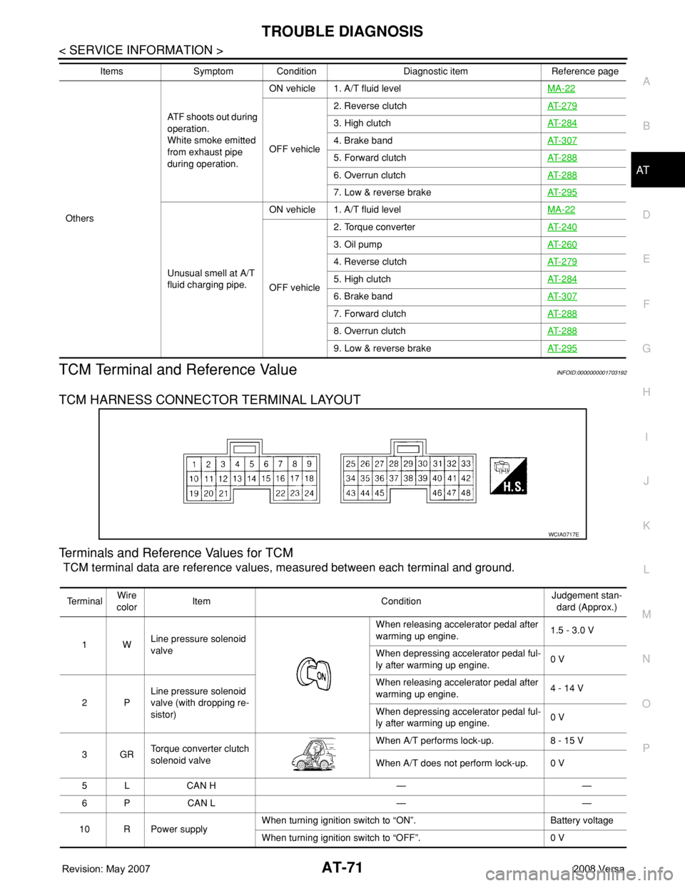
TCM Terminal and Reference ValueINFOID:0000000001703192
TCM HARNESS CONNECTOR TERMINAL LAYOUT
Terminals and Reference Values for TCM
TCM terminal data are reference values, measured between each terminal and ground.
OthersATF shoots out during
operation.
White smoke emitted
from exhaust pipe
during operation.ON vehicle 1. A/T fluid levelMA-22
OFF vehicle2. Reverse clutchAT- 2 7 9
3. High clutchAT- 2 8 4
4. Brake bandAT- 3 0 7
5. Forward clutchAT- 2 8 8
6. Overrun clutchAT- 2 8 8
7. Low & reverse brakeAT- 2 9 5
Unusual smell at A/T
fluid charging pipe.ON vehicle 1. A/T fluid levelMA-22
OFF vehicle2. Torque converterAT- 2 4 0
3. Oil pumpAT- 2 6 0
4. Reverse clutchAT- 2 7 9
5. High clutchAT- 2 8 4
6. Brake bandAT- 3 0 7
7. Forward clutchAT- 2 8 8
8. Overrun clutchAT- 2 8 8
9. Low & reverse brakeAT- 2 9 5
Items Symptom Condition Diagnostic item Reference page
WCIA0717E
Te r m i n a lWire
colorItem ConditionJudgement stan-
dard (Approx.)
1WLine pressure solenoid
valveWhen releasing accelerator pedal after
warming up engine.1.5 - 3.0 V
When depressing accelerator pedal ful-
ly after warming up engine.0 V
2PLine pressure solenoid
valve (with dropping re-
sistor)When releasing accelerator pedal after
warming up engine.4 - 14 V
When depressing accelerator pedal ful-
ly after warming up engine.0 V
3GRTorque converter clutch
solenoid valveWhen A/T performs lock-up. 8 - 15 V
When A/T does not perform lock-up. 0 V
5 L CAN H — —
6 P CAN L — —
10 R Power supplyWhen turning ignition switch to “ON”. Battery voltage
When turning ignition switch to “OFF”. 0 V
Page 84 of 2771
AT-72
< SERVICE INFORMATION >
TROUBLE DIAGNOSIS
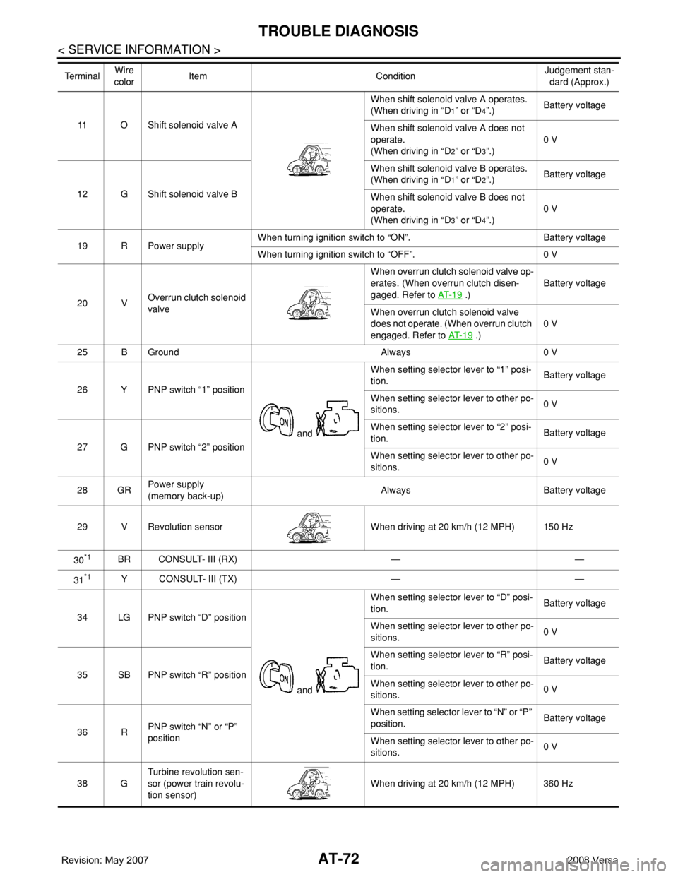
11 O Shift solenoid valve AWhen shift solenoid valve A operates.
(When driving in “D
1” or “D4”.)Battery voltage
When shift solenoid valve A does not
operate.
(When driving in “D
2” or “D3”.)0 V
12 G Shift solenoid valve BWhen shift solenoid valve B operates.
(When driving in “D
1” or “D2”.)Battery voltage
When shift solenoid valve B does not
operate.
(When driving in “D
3” or “D4”.)0 V
19 R Power supplyWhen turning ignition switch to “ON”. Battery voltage
When turning ignition switch to “OFF”. 0 V
20 VOverrun clutch solenoid
valveWhen overrun clutch solenoid valve op-
erates. (When overrun clutch disen-
gaged. Refer to AT- 1 9
.)Battery voltage
When overrun clutch solenoid valve
does not operate. (When overrun clutch
engaged. Refer to AT- 1 9
.)0 V
25 B Ground Always 0 V
26 Y PNP switch “1” position
and When setting selector lever to “1” posi-
tion.Battery voltage
When setting selector lever to other po-
sitions.0 V
27 G PNP switch “2” positionWhen setting selector lever to “2” posi-
tion.Battery voltage
When setting selector lever to other po-
sitions.0 V
28 GRPower supply
(memory back-up)Always Battery voltage
29 V Revolution sensor When driving at 20 km/h (12 MPH) 150 Hz
30
*1BR CONSULT- III (RX) — —
31
*1Y CONSULT- III (TX) — —
34 LG PNP switch “D” position
and When setting selector lever to “D” posi-
tion.Battery voltage
When setting selector lever to other po-
sitions.0 V
35 SB PNP switch “R” positionWhen setting selector lever to “R” posi-
tion.Battery voltage
When setting selector lever to other po-
sitions.0 V
36 RPNP switch “N” or “P”
positionWhen setting selector lever to “N” or “P”
position.Battery voltage
When setting selector lever to other po-
sitions.0 V
38 GTurbine revolution sen-
sor (power train revolu-
tion sensor)When driving at 20 km/h (12 MPH) 360 Hz Te r m i n a lWire
colorItem ConditionJudgement stan-
dard (Approx.)
Page 85 of 2771
TROUBLE DIAGNOSIS
AT-73
< SERVICE INFORMATION >
D
E
F
G
H
I
J
K
L
MA
B
AT
N
O
P
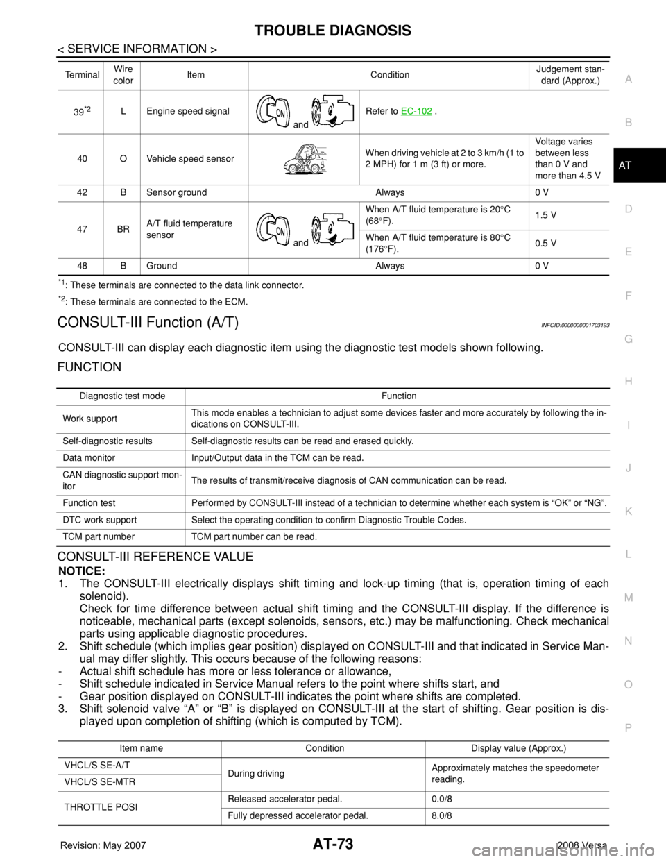
*1: These terminals are connected to the data link connector.
*2: These terminals are connected to the ECM.
CONSULT-III Function (A/T)INFOID:0000000001703193
CONSULT-III can display each diagnostic item using the diagnostic test models shown following.
FUNCTION
CONSULT-III REFERENCE VALUE
NOTICE:
1. The CONSULT-III electrically displays shift timing and lock-up timing (that is, operation timing of each
solenoid).
Check for time difference between actual shift timing and the CONSULT-III display. If the difference is
noticeable, mechanical parts (except solenoids, sensors, etc.) may be malfunctioning. Check mechanical
parts using applicable diagnostic procedures.
2. Shift schedule (which implies gear position) displayed on CONSULT-III and that indicated in Service Man-
ual may differ slightly. This occurs because of the following reasons:
- Actual shift schedule has more or less tolerance or allowance,
- Shift schedule indicated in Service Manual refers to the point where shifts start, and
- Gear position displayed on CONSULT-III indicates the point where shifts are completed.
3. Shift solenoid valve “A” or “B” is displayed on CONSULT-III at the start of shifting. Gear position is dis-
played upon completion of shifting (which is computed by TCM).
39*2L Engine speed signal
and Refer to EC-102 .
40 O Vehicle speed sensorWhen driving vehicle at 2 to 3 km/h (1 to
2 MPH) for 1 m (3 ft) or more.Voltage varies
between less
than 0 V and
more than 4.5 V
42 B Sensor ground Always 0 V
47 BRA/T fluid temperature
sensor
and When A/T fluid temperature is 20°C
(68°F).1.5 V
When A/T fluid temperature is 80°C
(176°F).0.5 V
48 B Ground Always 0 V Te r m i n a lWire
colorItem ConditionJudgement stan-
dard (Approx.)
Diagnostic test mode Function
Work supportThis mode enables a technician to adjust some devices faster and more accurately by following the in-
dications on CONSULT-III.
Self-diagnostic results Self-diagnostic results can be read and erased quickly.
Data monitor Input/Output data in the TCM can be read.
CAN diagnostic support mon-
itorThe results of transmit/receive diagnosis of CAN communication can be read.
Function test Performed by CONSULT-III instead of a technician to determine whether each system is “OK” or “NG”.
DTC work support Select the operating condition to confirm Diagnostic Trouble Codes.
TCM part number TCM part number can be read.
Item name Condition Display value (Approx.)
VHCL/S SE-A/T
During drivingApproximately matches the speedometer
reading.
VHCL/S SE-MTR
THROTTLE POSIReleased accelerator pedal. 0.0/8
Fully depressed accelerator pedal. 8.0/8
Page 100 of 2771

AT-88
< SERVICE INFORMATION >
DTC P0705 PARK/NEUTRAL POSITION (PNP) SWITCH
Diagnosis Procedure
INFOID:0000000001703207
1.CHECK INPUT SIGNAL
With CONSULT-III
1. Turn ignition switch ON. (Do not start engine.)
2. Select “TCM INPUT SIGNALS” in “DATA MONITOR” mode for “A/T” with CONSULT-III.
3. Read out “P·N”, “R”, “D”, “2” and “1” position switches moving selector lever to each position.
OK or NG
OK >> GO TO 6.
NG >> GO TO 3.
2.CHECK INPUT SIGNAL
Without CONSULT-III
1. Turn ignition switch ON. (Do not start engine.)
2. Check voltage between TCM connector terminals and ground
while moving selector lever through each position.
B: Battery voltage
0: 0V
OK or NG
OK >> GO TO 6.
Item name Condition Display value
PN POSI SWWhen setting selector lever to “N” or “P” posi-
tion.ON
When setting selector lever to other positions. OFF
R POSITION SWWhen setting selector lever to “R” position. ON
When setting selector lever to other positions. OFF
D POSITION SWWhen setting selector lever to “D” positions. ON
When setting selector lever to other positions. OFF
2 POSITION SWWhen setting selector lever to “2” position. ON
When setting selector lever to other positions. OFF
1 POSITION SWWhen setting selector lever to “1” position. ON
When setting selector lever to other positions. OFF
Selector lever positionTe r m i n a l
36 35 34 27 26
P, N B0000
R 0B000
D00B00
20 00B0
1 0000B
SCIA7162E
Page 105 of 2771
DTC P0710 A/T FLUID TEMPERATURE SENSOR CIRCUIT
AT-93
< SERVICE INFORMATION >
D
E
F
G
H
I
J
K
L
MA
B
AT
N
O
P
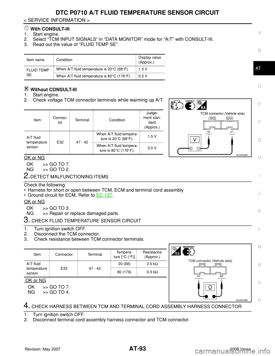
With CONSULT-III
1. Start engine.
2. Select “TCM INPUT SIGNALS” in “DATA MONITOR” mode for “A/T” with CONSULT-III.
3. Read out the value of “FLUID TEMP SE”.
Without CONSULT-III
1. Start engine.
2. Check voltage TCM connector terminals while warming up A/T.
OK or NG
OK >> GO TO 7.
NG >> GO TO 2.
2.DETECT MALFUNCTIONING ITEMS
Check the following.
• Harness for short or open between TCM, ECM and terminal cord assembly
• Ground circuit for ECM, Refer to EC-137
.
OK or NG
OK >> GO TO 3.
NG >> Repair or replace damaged parts.
3. CHECK FLUID TEMPERATURE SENSOR CIRCUIT
1. Turn ignition switch OFF.
2. Disconnect the TCM connector.
3. Check resistance between TCM connector terminals.
OK or NG
OK >> GO TO 7.
NG >> GO TO 4.
4. CHECK HARNESS BETWEEN TCM AND TERMINAL CORD ASSEMBLY HARNESS CONNECTOR
1. Turn ignition switch OFF.
2. Disconnect terminal cord assembly harness connector and TCM connector.
Item name ConditionDisplay value
(Approx.)
FLUID TEMP
SEWhen A/T fluid temperature is 20°C (68°F). 1.5 V
When A/T fluid temperature is 80°C (176°F). 0.5 V
ItemConnec-
torTerminal ConditionJudge-
ment stan-
dard
(Approx.)
A/T fluid
temperature
sensorE32 47 - 42When A/T fluid tempera-
ture is 20°C (68°F).1.5 V
When A/T fluid tempera-
ture is 80°C (176°F).0.5 V
SCIA2658E
Item Connector Terminal Te m p e r a -
ture [°C (°F)]Resistance
(Approx.)
A/T fluid
temperature
sensorE32 47 - 4220 (68) 2.5 kΩ
80 (176) 0.3 kΩ
SCIA2338E
Page 106 of 2771
AT-94
< SERVICE INFORMATION >
DTC P0710 A/T FLUID TEMPERATURE SENSOR CIRCUIT
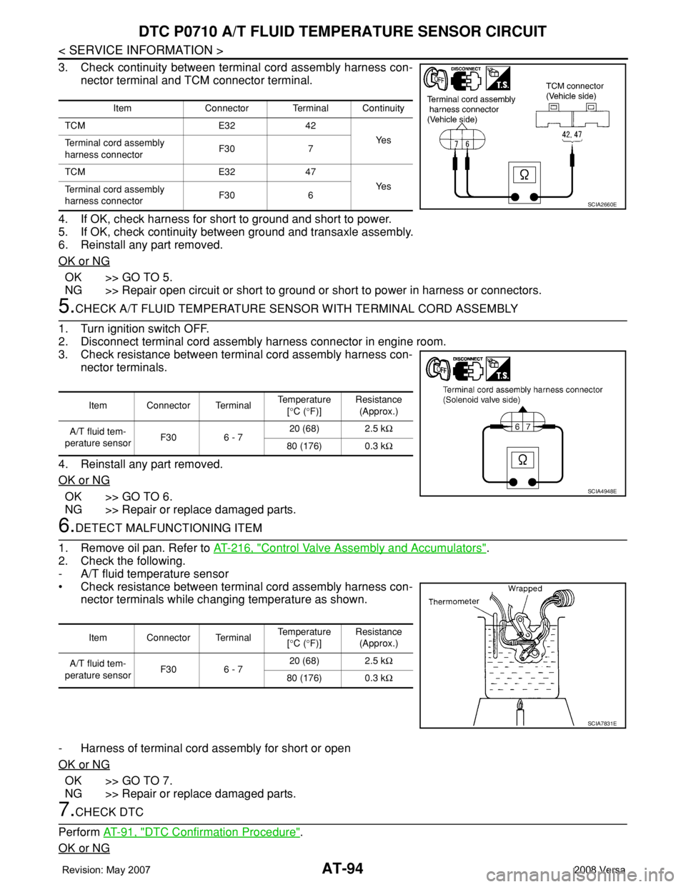
3. Check continuity between terminal cord assembly harness con-
nector terminal and TCM connector terminal.
4. If OK, check harness for short to ground and short to power.
5. If OK, check continuity between ground and transaxle assembly.
6. Reinstall any part removed.
OK or NG
OK >> GO TO 5.
NG >> Repair open circuit or short to ground or short to power in harness or connectors.
5.CHECK A/T FLUID TEMPERATURE SENSOR WITH TERMINAL CORD ASSEMBLY
1. Turn ignition switch OFF.
2. Disconnect terminal cord assembly harness connector in engine room.
3. Check resistance between terminal cord assembly harness con-
nector terminals.
4. Reinstall any part removed.
OK or NG
OK >> GO TO 6.
NG >> Repair or replace damaged parts.
6.DETECT MALFUNCTIONING ITEM
1. Remove oil pan. Refer to AT-216, "
Control Valve Assembly and Accumulators".
2. Check the following.
- A/T fluid temperature sensor
• Check resistance between terminal cord assembly harness con-
nector terminals while changing temperature as shown.
- Harness of terminal cord assembly for short or open
OK or NG
OK >> GO TO 7.
NG >> Repair or replace damaged parts.
7.CHECK DTC
Perform AT-91, "
DTC Confirmation Procedure".
OK or NG
Item Connector Terminal Continuity
TCM E32 42
Ye s
Terminal cord assembly
harness connectorF30 7
TCM E32 47
Ye s
Terminal cord assembly
harness connectorF30 6
SCIA2660E
Item Connector Terminal Temperature
[°C (°F)]Resistance
(Approx.)
A/T fluid tem-
perature sensorF30 6 - 720 (68) 2.5 kΩ
80 (176) 0.3 kΩ
SCIA4948E
Item Connector Terminal Temperature
[°C (°F)]Resistance
(Approx.)
A/T fluid tem-
perature sensorF30 6 - 720 (68) 2.5 kΩ
80 (176) 0.3 kΩ
SCIA7831E