Page 154 of 2771
AT-142
< SERVICE INFORMATION >
DTC P0755 SHIFT SOLENOID VALVE B
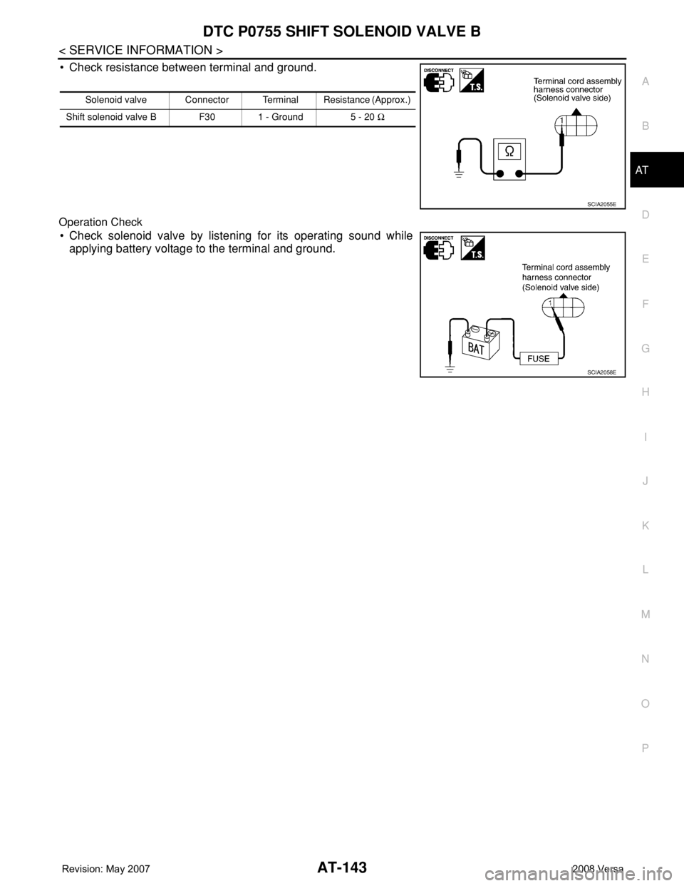
3. Check continuity between terminal cord assembly harness con-
nector terminal and TCM connector terminal.
4. If OK, check harness for short to ground and short to power.
5. If OK, check continuity between ground and transaxle assembly.
6. Reinstall any part removed.
OK or NG
OK >> GO TO 4.
NG >> Repair open circuit or short to ground or short to power in harness or connectors.
4.CHECK VALVE RESISTANCE
1. Turn ignition switch OFF.
2. Disconnect terminal cord assembly connector in engine room.
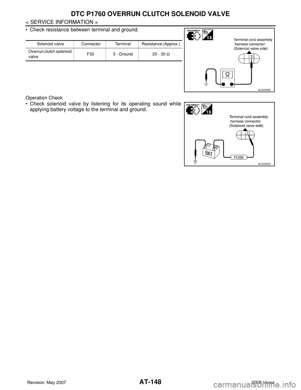
3. Check resistance between terminal cord assembly harness con-
nector terminal and ground.
OK or NG
OK >> GO TO 5.
NG >> Repair or replace damaged parts.
5.CHECK DTC
Perform AT-139, "
DTC Confirmation Procedure" .
OK or NG
OK >>INSPECTION END
NG >> GO TO 6.
6.CHECK TCM
1. Check TCM input/output signal. Refer to AT-71, "
TCM Terminal and Reference Value" .
2. If NG, recheck TCM pin terminals for damage or loose connection with harness connector.
OK or NG
OK >>INSPECTION END
NG >> Repair or replace damaged parts.
Component InspectionINFOID:0000000001703289
SHIFT SOLENOID VALVE B
• For removal, refer to AT-216, "Control Valve Assembly and Accumulators" .
Resistance Check
Item Connector Terminal Continuity
TCM E31 12
Ye s
Terminal cord assembly
harness connectorF30 1
SCIA3255E
Solenoid valve Connector Terminal Resistance (Approx.)
Shift solenoid valve B F30 1 - Ground 5 - 20 Ω
SCIA3454E
Page 155 of 2771
DTC P0755 SHIFT SOLENOID VALVE B
AT-143
< SERVICE INFORMATION >
D
E
F
G
H
I
J
K
L
MA
B
AT
N
O
P
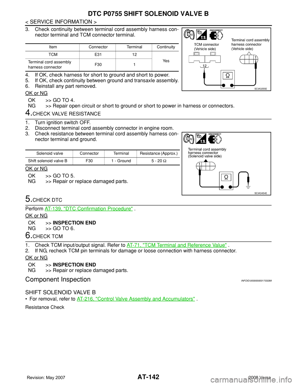
• Check resistance between terminal and ground.
Operation Check
• Check solenoid valve by listening for its operating sound while
applying battery voltage to the terminal and ground.
Solenoid valve Connector Terminal Resistance (Approx.)
Shift solenoid valve B F30 1 - Ground 5 - 20 Ω
SCIA2055E
SCIA2058E
Page 158 of 2771
AT-146
< SERVICE INFORMATION >
DTC P1760 OVERRUN CLUTCH SOLENOID VALVE
Diagnosis Procedure
INFOID:0000000001703296
1.CHECK INPUT SIGNAL
With CONSULT-III
1. Start engine.
2. Select “MAIN SIGNALS” in “DATA MONITOR” mode for “A/T” with CONSULT-III.
3. Read out the value of “OVERRUN/C S/V” while driving.
Check the value changes according to driving speed.
Without CONSULT-III
1. Start engine.
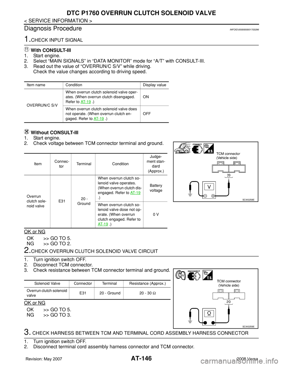
2. Check voltage between TCM connector terminal and ground.
OK or NG
OK >> GO TO 5.
NG >> GO TO 2.
2.CHECK OVERRUN CLUTCH SOLENOID VALVE CIRCUIT
1. Turn ignition switch OFF.
2. Disconnect TCM connector.
3. Check resistance between TCM connector terminal and ground.
OK or NG
OK >> GO TO 5.
NG >> GO TO 3.
3. CHECK HARNESS BETWEEN TCM AND TERMINAL CORD ASSEMBLY HARNESS CONNECTOR
1. Turn ignition switch OFF.
2. Disconnect terminal cord assembly harness connector and TCM connector.
Item name Condition Display value
OVERRUN/C S/VWhen overrun clutch solenoid valve oper-
ates. (When overrun clutch disengaged.
Refer to AT- 1 9
.)ON
When overrun clutch solenoid valve does
not operate. (When overrun clutch en-
gaged. Refer to AT- 1 9
.)OFF
Item Connec-
torTerminal ConditionJudge-
ment stan-
dard
(Approx.)
Overrun
clutch sole-
noid valve E31 20 -
GroundWhen overrun clutch so-
lenoid valve operates.
(When overrun clutch dis-
engaged. Refer to AT- 1 9
.)Battery
voltage
When overrun clutch so-
lenoid valve dose not op-
erate. (When overrun
clutch engaged. Refer to
AT- 1 9
.)0 V
SCIA3258E
Solenoid Valve Connector Terminal Resistance (Approx.)
Overrun clutch solenoid
valve E31 20 - Ground 20 - 30 Ω
SCIA3259E
Page 159 of 2771
DTC P1760 OVERRUN CLUTCH SOLENOID VALVE
AT-147
< SERVICE INFORMATION >
D
E
F
G
H
I
J
K
L
MA
B
AT
N
O
P
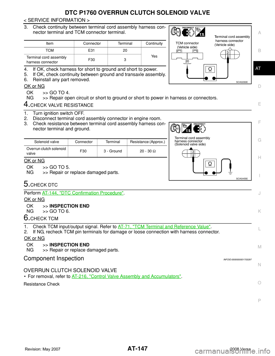
3. Check continuity between terminal cord assembly harness con-
nector terminal and TCM connector terminal.
4. If OK, check harness for short to ground and short to power.
5. If OK, check continuity between ground and transaxle assembly.
6. Reinstall any part removed.
OK or NG
OK >> GO TO 4.
NG >> Repair open circuit or short to ground or short to power in harness or connectors.
4.CHECK VALVE RESISTANCE
1. Turn ignition switch OFF.
2. Disconnect terminal cord assembly connector in engine room.
3. Check resistance between terminal cord assembly harness con-
nector terminal and ground.
OK or NG
OK >> GO TO 5.
NG >> Repair or replace damaged parts.
5.CHECK DTC
Perform AT-144, "
DTC Confirmation Procedure".
OK or NG
OK >>INSPECTION END
NG >> GO TO 6.
6.CHECK TCM
1. Check TCM input/output signal. Refer to AT-71, "
TCM Terminal and Reference Value".
2. If NG, recheck TCM pin terminals for damage or loose connection with harness connector.
OK or NG
OK >>INSPECTION END
NG >> Repair or replace damaged parts.
Component InspectionINFOID:0000000001703297
OVERRUN CLUTCH SOLENOID VALVE
• For removal, refer to AT-216, "Control Valve Assembly and Accumulators".
Resistance Check
Item Connector Terminal Continuity
TCM E31 20
Ye s
Terminal cord assembly
harness connectorF30 3
SCIA3260E
Solenoid valve Connector Terminal Resistance (Approx.)
Overrun clutch solenoid
valveF30 3 - Ground 20 - 30 Ω
SCIA3455E
Page 160 of 2771
AT-148
< SERVICE INFORMATION >
DTC P1760 OVERRUN CLUTCH SOLENOID VALVE
• Check resistance between terminal and ground.
Operation Check
• Check solenoid valve by listening for its operating sound while
applying battery voltage to the terminal and ground.
Solenoid valve Connector Terminal Resistance (Approx.)
Overrun clutch solenoid
valveF30 3 - Ground 20 - 30 Ω
SCIA2059E
SCIA2062E
Page 163 of 2771
DTC VEHICLE SPEED SENSOR MTR
AT-151
< SERVICE INFORMATION >
D
E
F
G
H
I
J
K
L
MA
B
AT
N
O
P
Diagnosis ProcedureINFOID:0000000001703304
1.CHECK INPUT SIGNAL
With CONSULT-III
1. Start engine.
2. Select “TCM INPUT SIGNALS” in “DATA MONITOR” mode for “A/T” with CONSULT-III.
3. Read out the value of “VHCL/S SE-MTR” while driving. Check the value changes according to driving
speed.
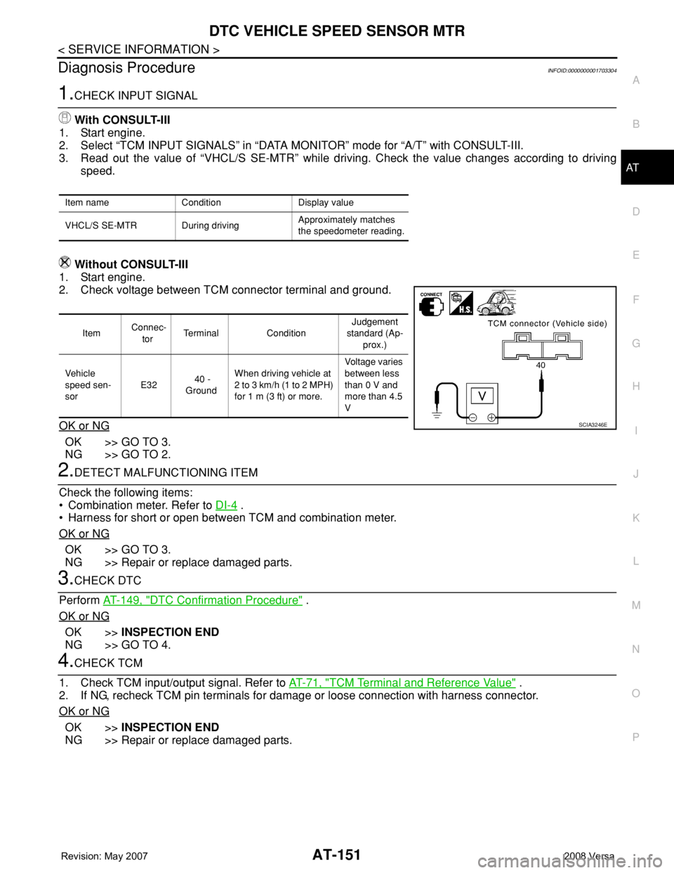
Without CONSULT-III
1. Start engine.
2. Check voltage between TCM connector terminal and ground.
OK or NG
OK >> GO TO 3.
NG >> GO TO 2.
2.DETECT MALFUNCTIONING ITEM
Check the following items:
• Combination meter. Refer to DI-4
.
• Harness for short or open between TCM and combination meter.
OK or NG
OK >> GO TO 3.
NG >> Repair or replace damaged parts.
3.CHECK DTC
Perform AT-149, "
DTC Confirmation Procedure" .
OK or NG
OK >>INSPECTION END
NG >> GO TO 4.
4.CHECK TCM
1. Check TCM input/output signal. Refer to AT-71, "
TCM Terminal and Reference Value" .
2. If NG, recheck TCM pin terminals for damage or loose connection with harness connector.
OK or NG
OK >>INSPECTION END
NG >> Repair or replace damaged parts.
Item name Condition Display value
VHCL/S SE-MTR During drivingApproximately matches
the speedometer reading.
Item Connec-
torTerminal ConditionJudgement
standard (Ap-
prox.)
Vehicle
speed sen-
sor E32 40 -
GroundWhen driving vehicle at
2 to 3 km/h (1 to 2 MPH)
for 1 m (3 ft) or more.Voltage varies
between less
than 0 V and
more than 4.5
V
SCIA3246E
Page 166 of 2771
AT-154
< SERVICE INFORMATION >
DTC BATT/FLUID TEMP SEN (A/T FLUID TEMP SENSOR CIRCUIT AND TCM
POWER SOURCE)
Diagnosis Procedure
INFOID:0000000001703311
1.CHECK TCM POWER SOURCE
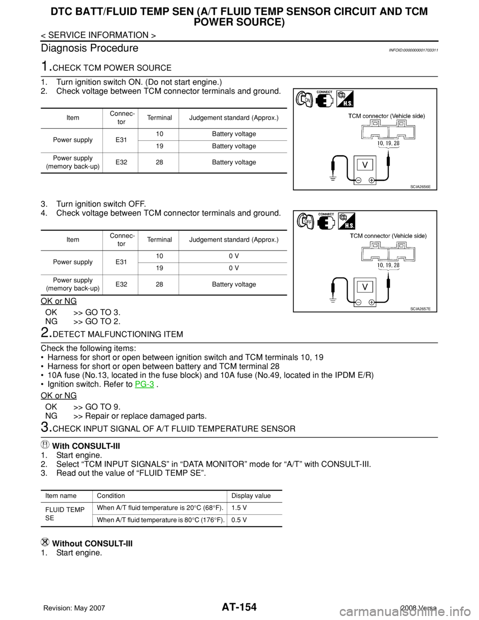
1. Turn ignition switch ON. (Do not start engine.)
2. Check voltage between TCM connector terminals and ground.
3. Turn ignition switch OFF.
4. Check voltage between TCM connector terminals and ground.
OK or NG
OK >> GO TO 3.
NG >> GO TO 2.
2.DETECT MALFUNCTIONING ITEM
Check the following items:
• Harness for short or open between ignition switch and TCM terminals 10, 19
• Harness for short or open between battery and TCM terminal 28
• 10A fuse (No.13, located in the fuse block) and 10A fuse (No.49, located in the IPDM E/R)
• Ignition switch. Refer to PG-3
.
OK or NG
OK >> GO TO 9.
NG >> Repair or replace damaged parts.
3.CHECK INPUT SIGNAL OF A/T FLUID TEMPERATURE SENSOR
With CONSULT-III
1. Start engine.
2. Select “TCM INPUT SIGNALS” in “DATA MONITOR” mode for “A/T” with CONSULT-III.
3. Read out the value of “FLUID TEMP SE”.
Without CONSULT-III
1. Start engine.
Item Connec-
torTerminal Judgement standard (Approx.)
Power supply E3110 Battery voltage
19 Battery voltage
Power supply
(memory back-up)E32 28 Battery voltage
SCIA2656E
Item Connec-
torTerminal Judgement standard (Approx.)
Power supply E3110 0 V
19 0 V
Power supply
(memory back-up)E32 28 Battery voltage
SCIA2657E
Item name Condition Display value
FLUID TEMP
SEWhen A/T fluid temperature is 20°C (68°F). 1.5 V
When A/T fluid temperature is 80°C (176°F). 0.5 V
Page 167 of 2771
DTC BATT/FLUID TEMP SEN (A/T FLUID TEMP SENSOR CIRCUIT AND TCM
POWER SOURCE)
AT-155
< SERVICE INFORMATION >
D
E
F
G
H
I
J
K
L
MA
B
AT
N
O
P
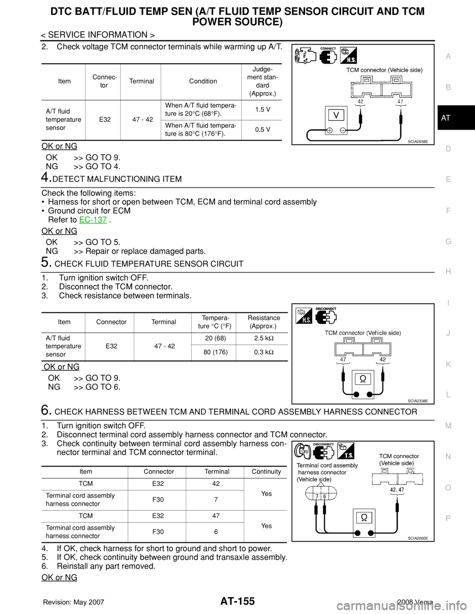
2. Check voltage TCM connector terminals while warming up A/T.
OK or NG
OK >> GO TO 9.
NG >> GO TO 4.
4.DETECT MALFUNCTIONING ITEM
Check the following items:
• Harness for short or open between TCM, ECM and terminal cord assembly
• Ground circuit for ECM
Refer to EC-137
.
OK or NG
OK >> GO TO 5.
NG >> Repair or replace damaged parts.
5. CHECK FLUID TEMPERATURE SENSOR CIRCUIT
1. Turn ignition switch OFF.
2. Disconnect the TCM connector.
3. Check resistance between terminals.
OK or NG
OK >> GO TO 9.
NG >> GO TO 6.
6. CHECK HARNESS BETWEEN TCM AND TERMINAL CORD ASSEMBLY HARNESS CONNECTOR
1. Turn ignition switch OFF.
2. Disconnect terminal cord assembly harness connector and TCM connector.
3. Check continuity between terminal cord assembly harness con-
nector terminal and TCM connector terminal.
4. If OK, check harness for short to ground and short to power.
5. If OK, check continuity between ground and transaxle assembly.
6. Reinstall any part removed.
OK or NG
Item Connec-
torTerminal ConditionJudge-
ment stan-
dard
(Approx.)
A/T fluid
temperature
sensor E32 47 - 42When A/T fluid tempera-
ture is 20°C (68°F).1.5 V
When A/T fluid tempera-
ture is 80°C (176°F).0.5 V
SCIA2658E
Item Connector Terminal Te m p e r a -
ture °C (°F) Resistance
(Approx.)
A/T fluid
temperature
sensor E32 47 - 42 20 (68) 2.5 kΩ
80 (176) 0.3 kΩ
SCIA2338E
Item Connector Terminal Continuity
TCM E32 42
Ye s
Terminal cord assembly
harness connectorF30 7
TCM E32 47
Ye s
Terminal cord assembly
harness connectorF30 6
SCIA2660E