2008 NISSAN TIIDA Supplemental Restraint System
[x] Cancel search: Supplemental Restraint SystemPage 2251 of 2771

LU-1
ENGINE
C
D
E
F
G
H
I
J
K
L
M
SECTION LU
A
LU
N
O
P
CONTENTS
ENGINE LUBRICATION SYSTEM
SERVICE INFORMATION ............................2
PRECAUTIONS ...................................................2
Precaution for Supplemental Restraint System
(SRS) "AIR BAG" and "SEAT BELT PRE-TEN-
SIONER" ...................................................................
2
Precaution for Liquid Gasket .....................................2
PREPARATION ...................................................3
Special Service Tool .................................................3
Commercial Service Tool ..........................................3
LUBRICATION SYSTEM ....................................5
Lubrication Circuit .....................................................5
ENGINE OIL .......................................................6
Inspection .................................................................6
Changing Engine Oil .................................................7
OIL FILTER ........................................................9
Removal and Installation ..........................................9
SERVICE DATA AND SPECIFICATIONS
(SDS) .................................................................
10
Standard and Limit ..................................................10
Page 2252 of 2771

LU-2
< SERVICE INFORMATION >
PRECAUTIONS
SERVICE INFORMATION
PRECAUTIONS
Precaution for Supplemental Restraint System (SRS) "AIR BAG" and "SEAT BELT
PRE-TENSIONER"
INFOID:0000000001790697
The Supplemental Restraint System such as “AIR BAG” and “SEAT BELT PRE-TENSIONER”, used along
with a front seat belt, helps to reduce the risk or severity of injury to the driver and front passenger for certain
types of collision. This system includes seat belt switch inputs and dual stage front air bag modules. The SRS
system uses the seat belt switches to determine the front air bag deployment, and may only deploy one front
air bag, depending on the severity of a collision and whether the front occupants are belted or unbelted.
Information necessary to service the system safely is included in the SRS and SB section of this Service Man-
ual.
WARNING:
• To avoid rendering the SRS inoperative, which could increase the risk of personal injury or death in
the event of a collision which would result in air bag inflation, all maintenance must be performed by
an authorized NISSAN/INFINITI dealer.
• Improper maintenance, including incorrect removal and installation of the SRS, can lead to personal
injury caused by unintentional activation of the system. For removal of Spiral Cable and Air Bag
Module, see the SRS section.
• Do not use electrical test equipment on any circuit related to the SRS unless instructed to in this
Service Manual. SRS wiring harnesses can be identified by yellow and/or orange harnesses or har-
ness connectors.
Precaution for Liquid GasketINFOID:0000000001702514
LIQUID GASKET APPLICATION PROCEDURE
1. Remove old liquid gasket adhering to the liquid gasket application surface and the mating surface.
• Remove liquid gasket completely from the liquid gasket application surface, bolts, and bolt holes.
2. Wipe the liquid gasket application surface and the mating surface with white gasoline (lighting and heating
use) to remove adhering moisture, grease and foreign materials.
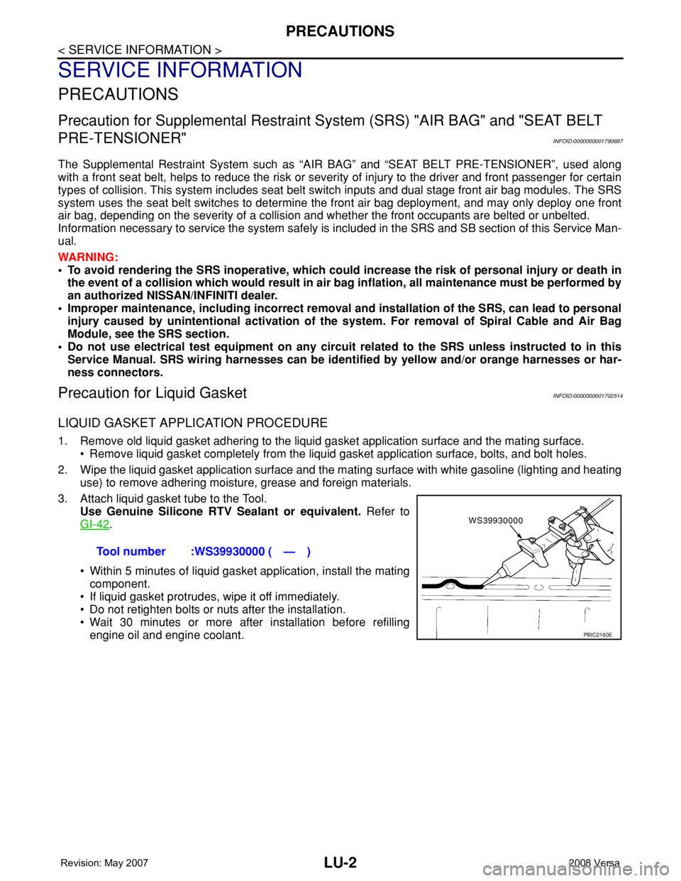
3. Attach liquid gasket tube to the Tool.
Use Genuine Silicone RTV Sealant or equivalent. Refer to
GI-42
.
• Within 5 minutes of liquid gasket application, install the mating
component.
• If liquid gasket protrudes, wipe it off immediately.
• Do not retighten bolts or nuts after the installation.
• Wait 30 minutes or more after installation before refilling
engine oil and engine coolant.Tool number :WS39930000 ( — )
PBIC2160E
Page 2261 of 2771

MA-1
MAINTENANCE
C
D
E
F
G
H
I
J
K
M
SECTION MA
A
B
MA
N
O
P
CONTENTS
MAINTENANCE
SERVICE INFORMATION ............................2
PRECAUTIONS ...................................................2
Precaution for Supplemental Restraint System
(SRS) "AIR BAG" and "SEAT BELT PRE-TEN-
SIONER" ...................................................................
2
PREPARATION ...................................................3
Special Service Tool .................................................3
Commercial Service Tool ..........................................3
GENERAL MAINTENANCE ................................4
Explanation of General Maintenance ........................4
General Maintenance ................................................4
PERIODIC MAINTENANCE ................................6
Introduction of Periodic Maintenance ........................6
Schedule 1 ................................................................6
Schedule 2 ................................................................8
RECOMMENDED FLUIDS AND LUBRI-
CANTS ................................................................
10
Fluids and Lubricants ..............................................10
SAE Viscosity Number ............................................10
Anti-freeze Coolant Mixture Ratio ...........................11
ENGINE MAINTENANCE ...................................12
Drive Belts ...............................................................12
Checking Drive Belts ...............................................12
Tension Adjustment ................................................12
Changing Engine Coolant .......................................12
Inspection ................................................................14
Checking Fuel Line ..................................................14
Changing Air Cleaner Filter .....................................14
Changing Engine Oil ................................................15
Engine Oil Filter .......................................................16
Changing Spark Plugs .............................................17
Checking EVAP Vapor Line .....................................18
CHASSIS AND BODY MAINTENANCE ...........19
Changing In-cabin Microfilter ...................................19
Checking Exhaust System .......................................19
Checking CVT Fluid .................................................19
Changing CVT Fluid ................................................20
Checking Clutch Fluid Level and Leaks ..................21
Checking Clutch System .........................................21
Checking M/T Oil .....................................................21
Changing M/T Oil .....................................................21
Checking A/T Fluid ..................................................22
Changing A/T Fluid ..................................................22
Balancing Wheels ....................................................23
Rotation ...................................................................23
Checking Brake Fluid Level and Leaks ...................23
Checking Brake Line and Cables ............................24
Changing Brake Fluid ..............................................24
Checking Disc Brake ...............................................24
Axle and Suspension Parts .....................................25
Drive Shaft ...............................................................26
Lubricating Locks, Hinges and Hood Latch .............27
Checking Seat Belts, Buckles, Retractors, An-
chors and Adjusters .................................................
27
Page 2262 of 2771

MA-2
< SERVICE INFORMATION >
PRECAUTIONS
SERVICE INFORMATION
PRECAUTIONS
Precaution for Supplemental Restraint System (SRS) "AIR BAG" and "SEAT BELT
PRE-TENSIONER"
INFOID:0000000001704717
The Supplemental Restraint System such as “AIR BAG” and “SEAT BELT PRE-TENSIONER”, used along
with a front seat belt, helps to reduce the risk or severity of injury to the driver and front passenger for certain
types of collision. This system includes seat belt switch inputs and dual stage front air bag modules. The SRS
system uses the seat belt switches to determine the front air bag deployment, and may only deploy one front
air bag, depending on the severity of a collision and whether the front occupants are belted or unbelted.
Information necessary to service the system safely is included in the SR and SB section of this Service Man-
ual.
WARNING:
• To avoid rendering the SRS inoperative, which could increase the risk of personal injury or death in
the event of a collision which would result in air bag inflation, all maintenance must be performed by
an authorized NISSAN/INFINITI dealer.
• Improper maintenance, including incorrect removal and installation of the SRS, can lead to personal
injury caused by unintentional activation of the system. For removal of Spiral Cable and Air Bag
Module, see the SR section.
• Do not use electrical test equipment on any circuit related to the SRS unless instructed to in this
Service Manual. SRS wiring harnesses can be identified by yellow and/or orange harnesses or har-
ness connectors.
Page 2289 of 2771

MT-1
TRANSMISSION/TRANSAXLE
D
E
F
G
H
I
J
K
L
M
SECTION MT
A
B
MT
N
O
P
CONTENTS
MANUAL TRANSAXLE
SERVICE INFORMATION ............................2
PRECAUTIONS ...................................................2
Precaution for Supplemental Restraint System
(SRS) "AIR BAG" and "SEAT BELT PRE-TEN-
SIONER" ...................................................................
2
Precaution for Procedure without Cowl Top Cover ......2
Precaution .................................................................2
PREPARATION ...................................................3
Special Service Tool .................................................3
Commercial Service Tool ..........................................5
NOISE, VIBRATION AND HARSHNESS
(NVH) TROUBLESHOOTING .............................
7
NVH Troubleshooting Chart ......................................7
DESCRIPTION ....................................................8
Cross-Sectional View ................................................8
M/T OIL ...............................................................10
Changing M/T Oil ....................................................10
Checking M/T Oil .....................................................10
SIDE OIL SEAL ..................................................11
Removal and Installation .........................................11
POSITION SWITCH ............................................12
Checking .................................................................12
CONTROL LINKAGE ........................................13
Component of Control Device and Cable ................13
Removal and Installation .........................................13
AIR BREATHER HOSE ....................................15
Removal and Installation .........................................15
TRANSAXLE ASSEMBLY ................................16
Removal and Installation .........................................16
Disassembly and Assembly .....................................17
INPUT SHAFT AND GEARS ............................35
Disassembly and Assembly .....................................35
MAINSHAFT AND GEARS ...............................39
Disassembly and Assembly .....................................39
REVERSE IDLER SHAFT AND GEARS ..........44
Disassembly and Assembly .....................................44
FINAL DRIVE ....................................................46
Disassembly and Assembly .....................................46
SHIFT CONTROL ..............................................49
Inspection ................................................................49
SERVICE DATA AND SPECIFICATIONS
(SDS) .................................................................
50
General Specification ..............................................50
Page 2290 of 2771

MT-2
< SERVICE INFORMATION >
PRECAUTIONS
SERVICE INFORMATION
PRECAUTIONS
Precaution for Supplemental Restraint System (SRS) "AIR BAG" and "SEAT BELT
PRE-TENSIONER"
INFOID:0000000001703128
The Supplemental Restraint System such as “AIR BAG” and “SEAT BELT PRE-TENSIONER”, used along
with a front seat belt, helps to reduce the risk or severity of injury to the driver and front passenger for certain
types of collision. This system includes seat belt switch inputs and dual stage front air bag modules. The SRS
system uses the seat belt switches to determine the front air bag deployment, and may only deploy one front
air bag, depending on the severity of a collision and whether the front occupants are belted or unbelted.
Information necessary to service the system safely is included in the SRS and SB section of this Service Man-
ual.
WARNING:
• To avoid rendering the SRS inoperative, which could increase the risk of personal injury or death in
the event of a collision which would result in air bag inflation, all maintenance must be performed by
an authorized NISSAN/INFINITI dealer.
• Improper maintenance, including incorrect removal and installation of the SRS, can lead to personal
injury caused by unintentional activation of the system. For removal of Spiral Cable and Air Bag
Module, see the SRS section.
• Do not use electrical test equipment on any circuit related to the SRS unless instructed to in this
Service Manual. SRS wiring harnesses can be identified by yellow and/or orange harnesses or har-
ness connectors.
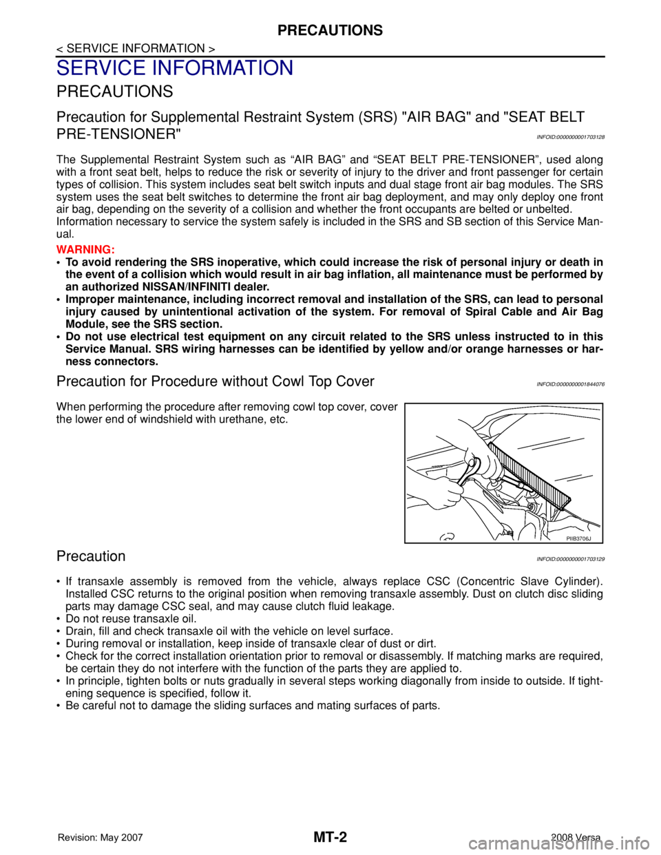
Precaution for Procedure without Cowl Top CoverINFOID:0000000001844076
When performing the procedure after removing cowl top cover, cover
the lower end of windshield with urethane, etc.
PrecautionINFOID:0000000001703129
• If transaxle assembly is removed from the vehicle, always replace CSC (Concentric Slave Cylinder).
Installed CSC returns to the original position when removing transaxle assembly. Dust on clutch disc sliding
parts may damage CSC seal, and may cause clutch fluid leakage.
• Do not reuse transaxle oil.
• Drain, fill and check transaxle oil with the vehicle on level surface.
• During removal or installation, keep inside of transaxle clear of dust or dirt.
• Check for the correct installation orientation prior to removal or disassembly. If matching marks are required,
be certain they do not interfere with the function of the parts they are applied to.
• In principle, tighten bolts or nuts gradually in several steps working diagonally from inside to outside. If tight-
ening sequence is specified, follow it.
• Be careful not to damage the sliding surfaces and mating surfaces of parts.
PIIB3706J
Page 2339 of 2771

MTC-1
AIR CONDITIONER
C
D
E
F
G
H
I
K
L
M
SECTION MTC
A
B
MTC
N
O
P
CONTENTS
MANUAL AIR CONDITIONER
SERVICE INFORMATION ............................3
PRECAUTIONS ...................................................3
Precaution for Supplemental Restraint System
(SRS) "AIR BAG" and "SEAT BELT PRE-TEN-
SIONER" ...................................................................
3
Precaution for Procedure without Cowl Top Cover ......3
Precaution for Working with HFC-134a (R-134a) ......3
General Refrigerant Precaution ................................4
Oil Precaution ............................................................4
Precaution for Refrigerant Connection ......................4
Precaution for Service of Compressor ......................7
Precaution for Service Equipment .............................7
Precaution for Leak Detection Dye ...........................9
PREPARATION ..................................................10
Special Service Tool ...............................................10
HFC-134a (R-134a) Service Tool and Equipment ....10
Commercial Service Tool ........................................13
REFRIGERATION SYSTEM ..............................14
Refrigerant Cycle ....................................................14
Refrigerant System Protection ................................14
Component Part Location .......................................15
OIL ......................................................................16
Maintenance of Oil Quantity in Compressor ...........16
AIR CONDITIONER CONTROL .........................19
Control Operation ....................................................19
Discharge Air Flow ..................................................20
System Description .................................................20
CAN Communication System Description ...............21
TROUBLE DIAGNOSIS .....................................22
CONSULT-III Function (BCM) .................................22
How to Perform Trouble Diagnosis for Quick and
Accurate Repair ......................................................
22
Component Parts and Harness Connector Loca-
tion ..........................................................................
23
Schematic ...............................................................25
Wiring Diagram - Heater - .......................................26
Wiring Diagram - A/C,M - ........................................27
Operational Check ...................................................30
Mode Door ...............................................................31
Air Mix Door .............................................................32
Intake Door ..............................................................33
Front Blower Motor Circuit .......................................33
Magnet Clutch Circuit (If Equipped) .........................37
Insufficient Cooling ..................................................45
Insufficient Heating ..................................................52
Noise .......................................................................53
CONTROLLER ..................................................55
Removal and Installation .........................................55
Disassembly and Assembly .....................................56
THERMO CONTROL AMPLIFIER ....................57
Removal and Installation .........................................57
A/C UNIT ASSEMBLY ......................................58
Removal and Installation .........................................58
Disassembly and Assembly .....................................60
BLOWER MOTOR ............................................62
Removal and Installation .........................................62
INTAKE DOOR ..................................................63
Intake Door Cable Adjustment .................................63
AIR MIX DOOR .................................................64
Air Mix Door Cable Adjustment ...............................64
MODE DOOR ....................................................65
Mode Door Cable Adjustment .................................65
BLOWER FAN RESISTOR ...............................66
Removal and Installation .........................................66
HEATER CORE .................................................67
Removal and Installation .........................................67
AIR CONDITIONER FILTER .............................68
Removal and Installation .........................................68
Page 2341 of 2771

PRECAUTIONS
MTC-3
< SERVICE INFORMATION >
C
D
E
F
G
H
I
K
L
MA
B
MTC
N
O
P
SERVICE INFORMATION
PRECAUTIONS
Precaution for Supplemental Restraint System (SRS) "AIR BAG" and "SEAT BELT
PRE-TENSIONER"
INFOID:0000000001704274
The Supplemental Restraint System such as “AIR BAG” and “SEAT BELT PRE-TENSIONER”, used along
with a front seat belt, helps to reduce the risk or severity of injury to the driver and front passenger for certain
types of collision. This system includes seat belt switch inputs and dual stage front air bag modules. The SRS
system uses the seat belt switches to determine the front air bag deployment, and may only deploy one front
air bag, depending on the severity of a collision and whether the front occupants are belted or unbelted.
Information necessary to service the system safely is included in the SRS and SB section of this Service Man-
ual.
WARNING:
• To avoid rendering the SRS inoperative, which could increase the risk of personal injury or death in
the event of a collision which would result in air bag inflation, all maintenance must be performed by
an authorized NISSAN/INFINITI dealer.
• Improper maintenance, including incorrect removal and installation of the SRS, can lead to personal
injury caused by unintentional activation of the system. For removal of Spiral Cable and Air Bag
Module, see the SRS section.
• Do not use electrical test equipment on any circuit related to the SRS unless instructed to in this
Service Manual. SRS wiring harnesses can be identified by yellow and/or orange harnesses or har-
ness connectors.
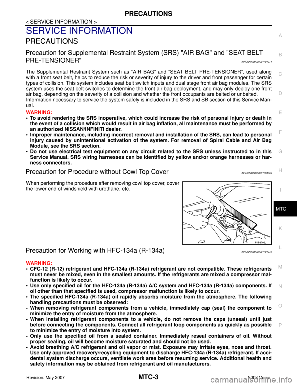
Precaution for Procedure without Cowl Top CoverINFOID:0000000001704275
When performing the procedure after removing cowl top cover, cover
the lower end of windshield with urethane, etc.
Precaution for Working with HFC-134a (R-134a)INFOID:0000000001704276
WARNING:
• CFC-12 (R-12) refrigerant and HFC-134a (R-134a) refrigerant are not compatible. These refrigerants
must never be mixed, even in the smallest amounts. If the refrigerants are mixed a compressor mal-
function is likely to occur.
• Use only specified oil for the HFC-134a (R-134a) A/C system and HFC-134a (R-134a) components. If
oil other than that specified is used, compressor malfunction is likely to occur.
• The specified HFC-134a (R-134a) oil rapidly absorbs moisture from the atmosphere. The following
handling precautions must be observed:
- When removing refrigerant components from a vehicle, immediately cap (seal) the component to
minimize the entry of moisture from the atmosphere.
- When installing refrigerant components to a vehicle, do not remove the caps (unseal) until just
before connecting the components. Connect all refrigerant loop components as quickly as possible
to minimize the entry of moisture into system.
- Only use the specified oil from a sealed container. Immediately reseal containers of oil. Without
proper sealing, oil will become moisture saturated and should not be used.
- Avoid breathing A/C refrigerant and oil vapor or mist. Exposure may irritate eyes, nose and throat.
Use only approved recovery/recycling equipment to discharge HFC-134a (R-134a) refrigerant. If acci-
dental system discharge occurs, ventilate work area before resuming service. Additional health and
safety information may be obtained from refrigerant and oil manufacturers.
PIIB3706J