2008 NISSAN TIIDA Supplemental Restraint System
[x] Cancel search: Supplemental Restraint SystemPage 1902 of 2771

GW-1
BODY
C
D
E
F
G
H
J
K
L
M
SECTION GW
A
B
GW
N
O
P
CONTENTS
GLASSES, WINDOW SYSTEM & MIRRORS
SERVICE INFORMATION ............................3
PRECAUTIONS ...................................................3
Precaution for Supplemental Restraint System
(SRS) "AIR BAG" and "SEAT BELT PRE-TEN-
SIONER" ...................................................................
3
Precaution for Procedure without Cowl Top Cover ......3
Handling for Adhesive and Primer ............................3
PREPARATION ...................................................4
Commercial Service Tool ..........................................4
SQUEAK AND RATTLE TROUBLE DIAG-
NOSES ................................................................
5
Work Flow .................................................................5
Generic Squeak and Rattle Troubleshooting ............7
Diagnostic Worksheet ...............................................9
WINDSHIELD GLASS ........................................11
Removal and Installation .........................................11
OPERA WINDOW GLASS .................................13
Removal and Installation .........................................13
REAR WINDOW GLASS AND MOLDING .........15
Removal and Installation .........................................15
POWER WINDOW SYSTEM ..............................18
Component Parts and Harness Connector Loca-
tion ..........................................................................
18
System Description .................................................18
CAN Communication System Description ...............22
Schematic ...............................................................22
Wiring Diagram - WINDOW- ...................................23
Main Power Window and Door Lock/Unlock
Switch Harness Connector Terminal Layout ...........
26
Terminal and Reference Value for Main Power
Window and Door Lock/Unlock Switch ...................
27
Terminal and Reference Value for BCM .................28
Work Flow ...............................................................28
CONSULT-III Function (BCM) .................................28
Power Window Auto Operation Initialization ...........29
Trouble Diagnosis Symptom Chart ..........................29
BCM Power Supply and Ground Circuit Inspection
....
30
Main Power Window and Door Lock/Unlock
Switch Power Supply and Ground Circuit Inspec-
tion ...........................................................................
30
Front Power Window Motor LH Circuit Inspection ....31
Front Power Window RH Circuit Inspection (Pow-
er Window and Door Lock/Unlock Switch RH Op-
eration) ....................................................................
32
Front Power Window Motor RH Circuit Inspection ....32
Encoder Circuit Inspection .......................................34
Door Switch Check ..................................................36
Rear Power Window LH Circuit Inspection (Rear
Power Window Switch LH Operation) .....................
37
Rear Power Window RH Circuit Inspection (Rear
Power Window Switch RH Operation) .....................
38
Rear Power Window Motor LH Circuit Inspection ....38
Rear Power Window Motor RH Circuit Inspection ....40
FRONT DOOR GLASS AND REGULATOR .....42
Removal and Installation .........................................42
Disassembly and Assembly .....................................44
Inspection after Installation ......................................44
REAR DOOR GLASS AND REGULATOR .......46
Removal and Installation .........................................46
Disassembly and Assembly .....................................48
Inspection after Installation ......................................48
REAR WINDOW DEFOGGER ..........................49
Component Parts and Harness Connector Loca-
tion ...........................................................................
49
System Description ..................................................49
CAN Communication System Description ...............50
Wiring Diagram - DEF - ...........................................51
Terminal and Reference Value for BCM ..................52
Terminal and Reference Value for IPDM E/R ..........52
Work Flow ................................................................53
CONSULT-III Function (BCM) .................................53
Trouble Diagnosis Symptom Chart ..........................53
Page 1904 of 2771
 \"AIR BAG\" and \"SEAT BELT
PRE-TE")
PRECAUTIONS
GW-3
< SERVICE INFORMATION >
C
D
E
F
G
H
J
K
L
MA
B
GW
N
O
P
SERVICE INFORMATION
PRECAUTIONS
Precaution for Supplemental Restraint System (SRS) "AIR BAG" and "SEAT BELT
PRE-TENSIONER"
INFOID:0000000001704128
The Supplemental Restraint System such as “AIR BAG” and “SEAT BELT PRE-TENSIONER”, used along
with a front seat belt, helps to reduce the risk or severity of injury to the driver and front passenger for certain
types of collision. This system includes seat belt switch inputs and dual stage front air bag modules. The SRS
system uses the seat belt switches to determine the front air bag deployment, and may only deploy one front
air bag, depending on the severity of a collision and whether the front occupants are belted or unbelted.
Information necessary to service the system safely is included in the SRS and SB section of this Service Man-
ual.
WARNING:
• To avoid rendering the SRS inoperative, which could increase the risk of personal injury or death in
the event of a collision which would result in air bag inflation, all maintenance must be performed by
an authorized NISSAN/INFINITI dealer.
• Improper maintenance, including incorrect removal and installation of the SRS, can lead to personal
injury caused by unintentional activation of the system. For removal of Spiral Cable and Air Bag
Module, see the SRS section.
• Do not use electrical test equipment on any circuit related to the SRS unless instructed to in this
Service Manual. SRS wiring harnesses can be identified by yellow and/or orange harnesses or har-
ness connectors.
Precaution for Procedure without Cowl Top CoverINFOID:0000000001704129
When performing the procedure after removing cowl top cover, cover
the lower end of windshield.
Handling for Adhesive and PrimerINFOID:0000000001704130
• Do not use an adhesive which is past its usable date. Shelf life of the adhesive is limited to six months after
the date of manufacture. Carefully adhere to the expiration or manufacture date printed on the box.
• Keep primers and adhesive in a cool, dry place. Ideally, they should be stored in a refrigerator.
• Open the seal of the primer and adhesive just before application. Discard the remainder after application.
• Before application, be sure to shake the primer container to stir the contents. If any floating material is found,
do not use it.
• If any primer or adhesive contacts the skin, wipe it off with gasoline or equivalent and wash the skin with
soap.
• When using primer and adhesive, always observe the precautions in the instruction manual.
PIIB3706J
Page 1967 of 2771

IP-1
BODY
C
D
E
F
G
H
J
K
L
M
SECTION IP
A
B
IP
N
O
P
CONTENTS
INSTRUMENT PANEL
PRECAUTION ...............................................2
PRECAUTIONS ...................................................2
Precaution for Supplemental Restraint System
(SRS) "AIR BAG" and "SEAT BELT PRE-TEN-
SIONER" ...................................................................
2
Precaution .................................................................2
PREPARATION ............................................3
PREPARATION ...................................................3
Special Service Tool .................................................3
Commercial Service Tool ..........................................3
SYMPTOM DIAGNOSIS ...............................4
SQUEAK AND RATTLE TROUBLE DIAG-
NOSES ...............................................................
4
Work Flow .................................................................4
Generic Squeak and Rattle Troubleshooting ............6
Diagnostic Worksheet ...............................................8
ON-VEHICLE REPAIR .................................10
INSTRUMENT PANEL ASSEMBLY .................10
Component Parts .....................................................10
Removal and Installation .........................................11
Disassembly and Assembly .....................................23
Page 1968 of 2771
 \"AIR BAG\" and \"SEAT BELT
PRE-TENSIONER\"
INFOID:0000000001704244
The Supplemen")
IP-2
< PRECAUTION >
PRECAUTIONS
PRECAUTION
PRECAUTIONS
Precaution for Supplemental Restraint System (SRS) "AIR BAG" and "SEAT BELT
PRE-TENSIONER"
INFOID:0000000001704244
The Supplemental Restraint System such as “AIR BAG” and “SEAT BELT PRE-TENSIONER”, used along
with a front seat belt, helps to reduce the risk or severity of injury to the driver and front passenger for certain
types of collision. This system includes seat belt switch inputs and dual stage front air bag modules. The SRS
system uses the seat belt switches to determine the front air bag deployment, and may only deploy one front
air bag, depending on the severity of a collision and whether the front occupants are belted or unbelted.
Information necessary to service the system safely is included in the SR and SB section of this Service Man-
ual.
WARNING:
• To avoid rendering the SRS inoperative, which could increase the risk of personal injury or death in
the event of a collision which would result in air bag inflation, all maintenance must be performed by
an authorized NISSAN/INFINITI dealer.
• Improper maintenance, including incorrect removal and installation of the SRS, can lead to personal
injury caused by unintentional activation of the system. For removal of Spiral Cable and Air Bag
Module, see the SR section.
• Do not use electrical test equipment on any circuit related to the SRS unless instructed to in this
Service Manual. SRS wiring harnesses can be identified by yellow and/or orange harnesses or har-
ness connectors.
PrecautionINFOID:0000000001704245
• Disconnect both battery terminals in advance.
• Disconnect air bag system line in advance.
• Never tamper with or force air bag lid open, as this may adversely affect air bag performance.
• Be careful not to scratch pad and other parts.
• When removing or disassembling any part, be careful not to damage or deform it. Protect parts which may
get in the way with cloth.
• When removing parts, protect parts by wrapping tools with vinyl or tape.
• Keep removed parts protected with cloth.
• If a clip is deformed or damaged, replace it.
• If an non-reusable part is removed, replace it with a new one.
• Tighten bolts and nuts firmly to the specified torque.
• After re-assembly has been completed, make sure each part functions correctly.
• Remove stains in the following way.
Water-soluble stains:
Dip a soft cloth in warm water, and then squeeze it tightly. After wiping the stain, wipe with a soft dry cloth.
Oil stain:
Dissolve a synthetic detergent in warm water (density of 2 to 3% or less), dip the cloth, then clean off the stain
with the cloth. Next, dip the cloth in fresh water and squeeze it tightly. Then clean off the detergent completely.
Then wipe the area with a soft dry cloth.
• Do not use any organic solvent, such as thinner or benzine.
Page 1992 of 2771

LAN-1
ELECTRICAL
C
D
E
F
G
H
I
J
L
M
SECTION LAN
A
B
LAN
N
O
P
CONTENTS
LAN SYSTEM
CAN FUNDAMENTAL
PRECAUTION ...............................................
5
PRECAUTIONS ...................................................5
Precautions for Trouble Diagnosis ............................5
Precautions for Harness Repair ................................5
FUNCTION DIAGNOSIS ...............................6
CAN COMMUNICATION SYSTEM .....................6
System Description ...................................................6
System Diagram ........................................................6
CAN Communication Control Circuit .........................7
DIAG ON CAN .....................................................8
Description ................................................................8
System Diagram ........................................................8
TROUBLE DIAGNOSIS ......................................9
Condition of Error Detection ......................................9
Symptom When Error Occurs in CAN Communi-
cation System ............................................................
9
CAN Diagnosis with CONSULT-III ..........................12
Self-Diagnosis .........................................................12
CAN Diagnostic Support Monitor ............................12
How to Use CAN Communication Signal Chart ......14
BASIC INSPECTION ...................................15
DIAGNOSIS AND REPAIR WORKFLOW .........15
Trouble Diagnosis Flow Chart .................................15
Trouble Diagnosis Procedure ..................................15
CAN
HOW TO USE THIS MANUAL .....................
20
HOW TO USE THIS SECTION ...........................20
Caution ....................................................................20
Abbreviation List ......................................................20
PRECAUTION ..............................................21
PRECAUTIONS .................................................21
Precaution for Supplemental Restraint System
(SRS) "AIR BAG" and "SEAT BELT PRE-TEN-
SIONER" .................................................................
21
Precautions for Trouble Diagnosis ..........................21
Precautions for Harness Repair ..............................21
BASIC INSPECTION ...................................22
DIAGNOSIS AND REPAIR WORKFLOW ........22
Interview Sheet ........................................................22
FUNCTION DIAGNOSIS ..............................23
CAN COMMUNICATION SYSTEM ...................23
CAN System Specification Chart .............................23
CAN Communication Signal Chart ..........................23
COMPONENT DIAGNOSIS .........................26
CAN COMMUNICATION SYSTEM ...................26
Component Parts Location ......................................26
Schematic ................................................................27
Wiring Diagram - CAN - ...........................................28
MALFUNCTION AREA CHART ........................30
Main Line .................................................................30
Branch Line .............................................................30
Short Circuit .............................................................30
MAIN LINE BETWEEN DLC AND ABS CIR-
CUIT ..................................................................
31
Diagnosis Procedure ...............................................31
MAIN LINE BETWEEN DLC AND TCM CIR-
CUIT ..................................................................
32
Diagnosis Procedure ...............................................32
ECM BRANCH LINE CIRCUIT .........................33
Diagnosis Procedure ...............................................33
BCM BRANCH LINE CIRCUIT .........................34
Diagnosis Procedure ...............................................34
Page 2012 of 2771
PRECAUTIONS
LAN-21
< PRECAUTION >[CAN]
C
D
E
F
G
H
I
J
L
MA
B
LAN
N
O
P
PRECAUTION
PRECAUTIONS
Precaution for Supplemental Restraint System (SRS) "AIR BAG" and "SEAT BELT
PRE-TENSIONER"
INFOID:0000000001711215
The Supplemental Restraint System such as “AIR BAG” and “SEAT BELT PRE-TENSIONER”, used along
with a front seat belt, helps to reduce the risk or severity of injury to the driver and front passenger for certain
types of collision. Information necessary to service the system safely is included in the “SRS AIRBAG” and
“SEAT BELT” of this Service Manual.
WARNING:
• To avoid rendering the SRS inoperative, which could increase the risk of personal injury or death in
the event of a collision which would result in air bag inflation, all maintenance must be performed by
an authorized NISSAN/INFINITI dealer.
• Improper maintenance, including incorrect removal and installation of the SRS, can lead to personal
injury caused by unintentional activation of the system. For removal of Spiral Cable and Air Bag
Module, see the “SRS AIRBAG”.
• Do not use electrical test equipment on any circuit related to the SRS unless instructed to in this
Service Manual. SRS wiring harnesses can be identified by yellow and/or orange harnesses or har-
ness connectors.
Precautions for Trouble DiagnosisINFOID:0000000001711216
CAUTION:
• Never apply 7.0 V or more to the measurement terminal.
• Use a tester with open terminal voltage of 7.0 V or less.
• Turn the ignition switch OFF and disconnect the battery cable from the negative terminal when
checking the harness.
Precautions for Harness RepairINFOID:0000000001711217
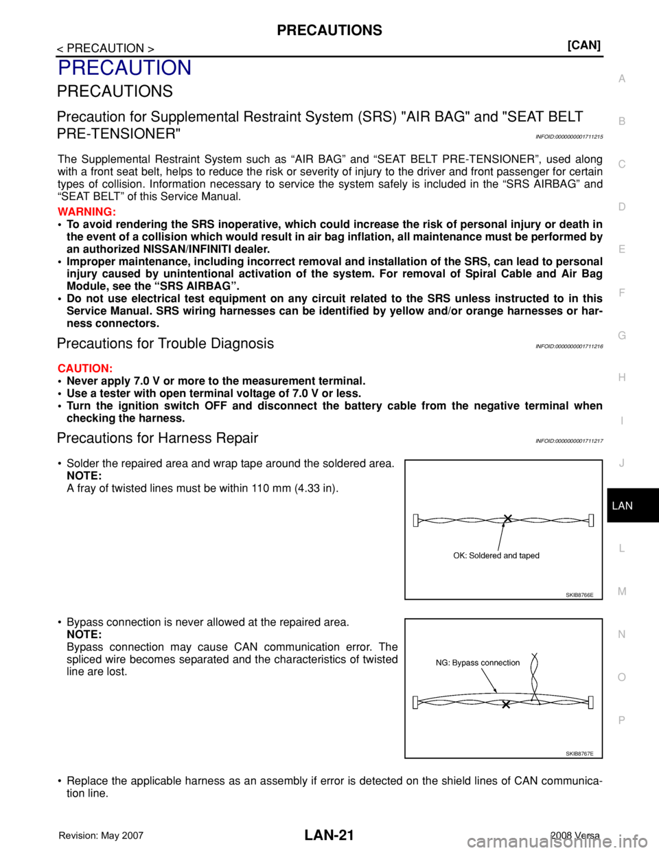
• Solder the repaired area and wrap tape around the soldered area.
NOTE:
A fray of twisted lines must be within 110 mm (4.33 in).
• Bypass connection is never allowed at the repaired area.
NOTE:
Bypass connection may cause CAN communication error. The
spliced wire becomes separated and the characteristics of twisted
line are lost.
• Replace the applicable harness as an assembly if error is detected on the shield lines of CAN communica-
tion line.
SKIB8766E
SKIB8767E
Page 2138 of 2771

LT-1
ELECTRICAL
C
D
E
F
G
H
I
J
L
M
SECTION LT
A
B
LT
N
O
P
CONTENTS
LIGHTING SYSTEM
SERVICE INFORMATION ............................3
PRECAUTIONS ...................................................3
Precaution for Supplemental Restraint System
(SRS) "AIR BAG" and "SEAT BELT PRE-TEN-
SIONER" ...................................................................
3
HEADLAMP (FOR USA) .....................................4
Component Parts and Harness Connector Loca-
tion ............................................................................
4
System Description ...................................................4
CAN COMMUNICATION SYSTEM DESCRIP-
TION ..........................................................................
5
Schematic .................................................................6
Wiring Diagram .........................................................7
Terminal and Reference Value for BCM .................10
Terminal and Reference Value for IPDM E/R .........10
How to Perform Trouble Diagnosis .........................11
Preliminary Check ...................................................11
CONSULT-III Function (BCM) .................................11
CONSULT-III Function (IPDM E/R) .........................12
Headlamp High Beam Does Not Illuminate (Both
Sides) ......................................................................
13
Headlamp High Beam Does Not Illuminate (One
Side) ........................................................................
15
High Beam Indicator Lamp Does Not Illuminate .....16
Headlamp Low Beam Does Not Illuminate (Both
Sides) ......................................................................
16
Headlamp Low Beam Does Not Illuminate (One
Side) ........................................................................
19
Headlamps Do Not Turn OFF .................................20
Aiming Adjustment ..................................................21
Bulb Replacement ...................................................22
Removal and Installation .........................................23
Disassembly and Assembly ....................................23
HEADLAMP (FOR CANADA) - DAYTIME
LIGHT SYSTEM - ...............................................
25
Component Parts and Harness Connector Loca-
tion ..........................................................................
25
System Description .................................................25
CAN Communication System Description ...............27
Schematic ................................................................28
Wiring Diagram - DTRL - .........................................29
Terminal and Reference Value for BCM ..................32
Terminal and Reference Value for IPDM E/R ..........32
How to Perform Trouble Diagnosis ..........................33
Preliminary Check ...................................................33
CONSULT-III Function (BCM) .................................33
CONSULT-III Function (IPDM E/R) .........................33
Daytime Light Control Does Not Operate Properly
(High Beam Headlamps Operate Properly) .............
33
Aiming Adjustment ...................................................35
Bulb Replacement ...................................................36
Removal and Installation .........................................37
Disassembly and Assembly .....................................37
FRONT FOG LAMP ..........................................39
Component Parts and Harness Connector Loca-
tion ...........................................................................
39
System Description ..................................................39
CAN Communication System Description ...............40
Wiring Diagram - F/FOG - .......................................41
Terminal and Reference Value for BCM ..................42
Terminal and Reference Value for IPDM E/R ..........42
How to Proceed with Trouble Diagnosis ..................43
Preliminary Check ...................................................43
CONSULT-III Function (BCM) .................................43
CONSULT-III Function (IPDM E/R) .........................43
Front Fog lamps Do Not Illuminate (Both Sides) .....43
Front Fog Lamp Does Not Illuminate (One Side) ....45
Aiming Adjustment ...................................................46
Bulb Replacement ...................................................47
Removal and Installation .........................................47
TURN SIGNAL AND HAZARD WARNING
LAMPS ..............................................................
48
Component Parts and Harness Connector Loca-
tion ...........................................................................
48
System Description ..................................................48
CAN Communication System Description ...............50
Schematic ................................................................51
Page 2140 of 2771
 \"AIR BAG\" and \"SEAT BELT
PRE-TE")
PRECAUTIONS
LT-3
< SERVICE INFORMATION >
C
D
E
F
G
H
I
J
L
MA
B
LT
N
O
P
SERVICE INFORMATION
PRECAUTIONS
Precaution for Supplemental Restraint System (SRS) "AIR BAG" and "SEAT BELT
PRE-TENSIONER"
INFOID:0000000001704359
The Supplemental Restraint System such as “AIR BAG” and “SEAT BELT PRE-TENSIONER”, used along
with a front seat belt, helps to reduce the risk or severity of injury to the driver and front passenger for certain
types of collision. This system includes seat belt switch inputs and dual stage front air bag modules. The SRS
system uses the seat belt switches to determine the front air bag deployment, and may only deploy one front
air bag, depending on the severity of a collision and whether the front occupants are belted or unbelted.
Information necessary to service the system safely is included in the SRS and SB section of this Service Man-
ual.
WARNING:
• To avoid rendering the SRS inoperative, which could increase the risk of personal injury or death in
the event of a collision which would result in air bag inflation, all maintenance must be performed by
an authorized NISSAN/INFINITI dealer.
• Improper maintenance, including incorrect removal and installation of the SRS, can lead to personal
injury caused by unintentional activation of the system. For removal of Spiral Cable and Air Bag
Module, see the SRS section.
• Do not use electrical test equipment on any circuit related to the SRS unless instructed to in this
Service Manual. SRS wiring harnesses can be identified by yellow and/or orange harnesses or har-
ness connectors.