2008 NISSAN TIIDA PN switch
[x] Cancel search: PN switchPage 1197 of 2771

TROUBLE DIAGNOSIS
EC-123
< SERVICE INFORMATION >
C
D
E
F
G
H
I
J
K
L
MA
EC
N
P O
INT/V SOL (B1)• Engine: After warming up
• Air conditioner switch: OFF
• Shift lever: P or N (A/T, CVT),
Neutral (M/T)
•No loadIdle 0% - 2%
When revving engine up to 2,000 rpm
quicklyApprox. 0% - 90%
AIR COND RLY• Engine: After warming up, idle the
engineAir conditioner switch: OFF OFF
Air conditioner switch: ON
(Compressor operates)ON
FUEL PUMP RLY• For 1 second after turning ignition switch ON
• Engine running or crankingON
• Except above conditions OFF
VENT CONT/V • Ignition switch: ON OFF
THRTL RELAY • Ignition switch: ON ON
COOLING FAN• Engine: After warming up, idle the
engine
• Air conditioner switch: OFFEngine coolant temperature: 97°C
(207°F) or lessOFF
Engine coolant temperature: Between
98°C (208°F) and 99°C (210°F)LOW
Engine coolant temperature: 100°C
(212°F) or moreHIGH
HO2S2 HTR (B1)• Below 3,600 rpm after the following conditions are met.
- Engine: After warming up
- Keeping the engine speed between 3,500 and 4,000 rpm for 1 minute and
at idle for 1 minute under no loadON
• Engine speed: Above 3,600 rpm OFF
I/P PULLY SPD • Vehicle speed: More than 20 km/h (12 MPH)Almost the same speed as the
tachometer indication
VEHICLE SPEED• Turn drive wheels and compare CONSULT-II value with the speedometer
indication.Almost the same speed as the
speedometer indication
TRVL AFTER MIL • Ignition switch: ONVehicle has traveled after MIL has
turned ON.0 - 65,535 km
(0 - 40,723 mile)
A/F S1 HTR (B1)• Engine: After warming up, idle the engine
(More than 140 seconds after starting engine.)4 - 100%
AC PRESS SEN• Engine: Idle
• Air conditioner switch: ON (Compressor operates)1.0 - 4.0V
VHCL SPEED SE• Turn drive wheels and compare speedometer indication with the CONSULT-
II value.Almost the same speed as the
speedometer indication
SET VHCL SPD • Engine: Running ASCD: OperatingThe preset vehicle speed is
displayed.
MAIN SW • Ignition switch: ONMAIN switch: Pressed ON
MAIN switch: Released OFF
CANCEL SW • Ignition switch: ONCANCEL switch: Pressed ON
CANCEL switch: Released OFF
RESUME/ACC SW • Ignition switch: ONRESUME/ACCELERATE switch:
PressedON
RESUME/ACCELERATE switch: Re-
leased
OFF
SET SW • Ignition switch: ONSET/COAST switch: Pressed ON
SET/COAST switch: Released OFF MONITOR ITEM CONDITION SPECIFICATION
Page 1198 of 2771
EC-124
< SERVICE INFORMATION >
TROUBLE DIAGNOSIS
*: Accelerator pedal position sensor 2 signal and throttle position sensor 2 signal are converted by ECM internally. Thus, they differ from
ECM terminals voltage signal.
Major Sensor Reference Graph in Data Monitor ModeINFOID:0000000001702598
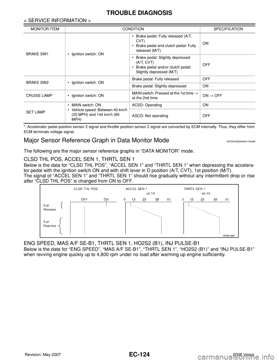
The following are the major sensor reference graphs in “DATA MONITOR” mode.
CLSD THL POS, ACCEL SEN 1, THRTL SEN 1
Below is the data for “CLSD THL POS”, “ACCEL SEN 1” and “THRTL SEN 1” when depressing the accelera-
tor pedal with the ignition switch ON and with shift lever in D position (A/T, CVT), 1st position (M/T).
The signal of “ACCEL SEN 1” and “THRTL SEN 1” should rise gradually without any intermittent drop or rise
after “CLSD THL POS” is changed from ON to OFF.
ENG SPEED, MAS A/F SE-B1, THRTL SEN 1, HO2S2 (B1), INJ PULSE-B1
Below is the data for “ENG SPEED”, “MAS A/F SE-B1”, “THRTL SEN 1”, “HO2S2 (B1)” and “INJ PULSE-B1”
when revving engine quickly up to 4,800 rpm under no load after warming up engine sufficiently.
BRAKE SW1 • Ignition switch: ON• Brake pedal: Fully released (A/T,
CVT)
• Brake pedal and clutch pedal: Fully
released (M/T)ON
• Brake pedal: Slightly depressed
(A/T, CVT)
• Brake pedal and/or clutch pedal:
Slightly depressed (M/T)OFF
BRAKE SW2 • Ignition switch: ONBrake pedal: Fully released OFF
Brake pedal: Slightly depressed ON
CRUISE LAMP • Ignition switch: ONMAIN switch: Pressed at the 1st time →
at the 2nd timeON → OFF
SET LAMP• MAIN switch: ON
• Vehicle speed: Between 40 km/h
(25 MPH) and 144 km/h (89
MPH)ACSD: Operating ON
ASCD: Not operating OFF MONITOR ITEM CONDITION SPECIFICATION
PBIB0198E
Page 1201 of 2771
TROUBLE DIAGNOSIS - SPECIFICATION VALUE
EC-127
< SERVICE INFORMATION >
C
D
E
F
G
H
I
J
K
L
MA
EC
N
P O
TROUBLE DIAGNOSIS - SPECIFICATION VALUE
DescriptionINFOID:0000000001702599
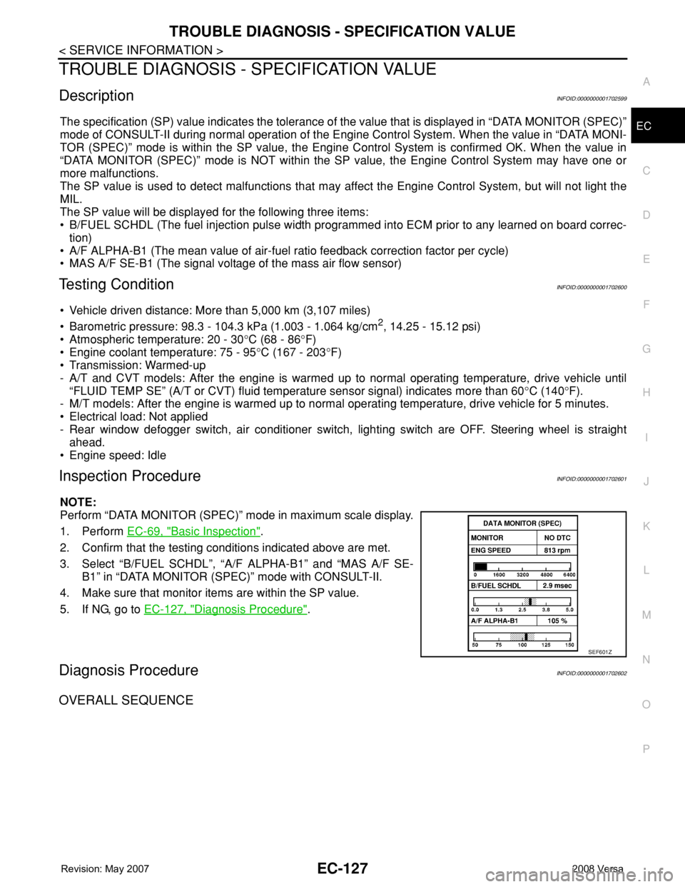
The specification (SP) value indicates the tolerance of the value that is displayed in “DATA MONITOR (SPEC)”
mode of CONSULT-II during normal operation of the Engine Control System. When the value in “DATA MONI-
TOR (SPEC)” mode is within the SP value, the Engine Control System is confirmed OK. When the value in
“DATA MONITOR (SPEC)” mode is NOT within the SP value, the Engine Control System may have one or
more malfunctions.
The SP value is used to detect malfunctions that may affect the Engine Control System, but will not light the
MIL.
The SP value will be displayed for the following three items:
• B/FUEL SCHDL (The fuel injection pulse width programmed into ECM prior to any learned on board correc-
tion)
• A/F ALPHA-B1 (The mean value of air-fuel ratio feedback correction factor per cycle)
• MAS A/F SE-B1 (The signal voltage of the mass air flow sensor)
Testing ConditionINFOID:0000000001702600
• Vehicle driven distance: More than 5,000 km (3,107 miles)
• Barometric pressure: 98.3 - 104.3 kPa (1.003 - 1.064 kg/cm
2, 14.25 - 15.12 psi)
• Atmospheric temperature: 20 - 30°C (68 - 86°F)
• Engine coolant temperature: 75 - 95°C (167 - 203°F)
• Transmission: Warmed-up
- A/T and CVT models: After the engine is warmed up to normal operating temperature, drive vehicle until
“FLUID TEMP SE” (A/T or CVT) fluid temperature sensor signal) indicates more than 60°C (140°F).
- M/T models: After the engine is warmed up to normal operating temperature, drive vehicle for 5 minutes.
• Electrical load: Not applied
- Rear window defogger switch, air conditioner switch, lighting switch are OFF. Steering wheel is straight
ahead.
• Engine speed: Idle
Inspection ProcedureINFOID:0000000001702601
NOTE:
Perform “DATA MONITOR (SPEC)” mode in maximum scale display.
1. Perform EC-69, "
Basic Inspection".
2. Confirm that the testing conditions indicated above are met.
3. Select “B/FUEL SCHDL”, “A/F ALPHA-B1” and “MAS A/F SE-
B1” in “DATA MONITOR (SPEC)” mode with CONSULT-II.
4. Make sure that monitor items are within the SP value.
5. If NG, go to EC-127, "
Diagnosis Procedure".
Diagnosis ProcedureINFOID:0000000001702602
OVERALL SEQUENCE
SEF601Z
Page 1212 of 2771
EC-138
< SERVICE INFORMATION >
POWER SUPPLY AND GROUND CIRCUIT
Diagnosis Procedure
INFOID:0000000001702606
1.INSPECTION START
Start engine.
Is engine running?
Ye s o r N o
Ye s > > G O T O 8 .
No >> GO TO 2.
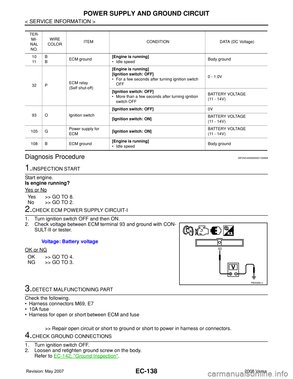
2.CHECK ECM POWER SUPPLY CIRCUIT-I
1. Turn ignition switch OFF and then ON.
2. Check voltage between ECM terminal 93 and ground with CON-
SULT-II or tester.
OK or NG
OK >> GO TO 4.
NG >> GO TO 3.
3.DETECT MALFUNCTIONING PART
Check the following.
• Harness connectors M69, E7
• 10A fuse
• Harness for open or short between ECM and fuse
>> Repair open circuit or short to ground or short to power in harness or connectors.
4.CHECK GROUND CONNECTIONS
1. Turn ignition switch OFF.
2. Loosen and retighten ground screw on the body.
Refer to EC-142, "
Ground Inspection".
TER-
MI-
NAL
NO.WIRE
COLORITEM CONDITION DATA (DC Voltage)
10
11B
BECM ground[Engine is running]
• Idle speedBody ground
32 PECM relay
(Self shut-off)[Engine is running]
[Ignition switch: OFF]
• For a few seconds after turning ignition switch
OFF0 - 1.0V
[Ignition switch: OFF]
• More than a few seconds after turning ignition
switch OFFBATTERY VOLTAGE
(11 - 14V)
93 O Ignition switch[Ignition switch: OFF]0V
[Ignition switch: ON]BATTERY VOLTAGE
(11 - 14V)
105 GPower supply for
ECM[Ignition switch: ON]BATTERY VOLTAGE
(11 - 14V)
108 B ECM ground[Engine is running]
• Idle speedBody ground
Voltage: Battery voltage
PBIA9561J
Page 1213 of 2771
POWER SUPPLY AND GROUND CIRCUIT
EC-139
< SERVICE INFORMATION >
C
D
E
F
G
H
I
J
K
L
MA
EC
N
P O
OK or NG
OK >> GO TO 5.
NG >> Repair or replace ground connections.
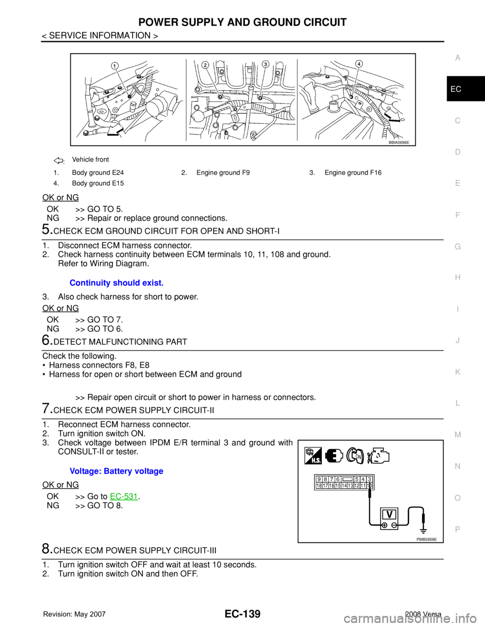
5.CHECK ECM GROUND CIRCUIT FOR OPEN AND SHORT-I
1. Disconnect ECM harness connector.
2. Check harness continuity between ECM terminals 10, 11, 108 and ground.
Refer to Wiring Diagram.
3. Also check harness for short to power.
OK or NG
OK >> GO TO 7.
NG >> GO TO 6.
6.DETECT MALFUNCTIONING PART
Check the following.
• Harness connectors F8, E8
• Harness for open or short between ECM and ground
>> Repair open circuit or short to power in harness or connectors.
7.CHECK ECM POWER SUPPLY CIRCUIT-II
1. Reconnect ECM harness connector.
2. Turn ignition switch ON.
3. Check voltage between IPDM E/R terminal 3 and ground with
CONSULT-II or tester.
OK or NG
OK >> Go to EC-531.
NG >> GO TO 8.
8.CHECK ECM POWER SUPPLY CIRCUIT-III
1. Turn ignition switch OFF and wait at least 10 seconds.
2. Turn ignition switch ON and then OFF.
:Vehicle front
1. Body ground E24 2. Engine ground F9 3. Engine ground F16
4. Body ground E15
BBIA0698E
Continuity should exist.
Voltage: Battery voltage
PBIB2658E
Page 1214 of 2771
EC-140
< SERVICE INFORMATION >
POWER SUPPLY AND GROUND CIRCUIT
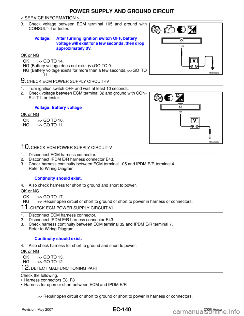
3. Check voltage between ECM terminal 105 and ground with
CONSULT-II or tester.
OK or NG
OK >> GO TO 14.
NG (Battery voltage does not exist.)>>GO TO 9.
NG (Battery voltage exists for more than a few seconds.)>>GO TO
11 .
9.CHECK ECM POWER SUPPLY CIRCUIT-IV
1. Turn ignition switch OFF and wait at least 10 seconds.
2. Check voltage between ECM terminal 32 and ground with CON-
SULT-II or tester.
OK or NG
OK >> GO TO 10.
NG >> GO TO 11.
10.CHECK ECM POWER SUPPLY CIRCUIT-V
1. Disconnect ECM harness connector.
2. Disconnect IPDM E/R harness connector E43.
3. Check harness continuity between ECM terminal 105 and IPDM E/R terminal 4.
Refer to Wiring Diagram.
4. Also check harness for short to ground and short to power.
OK or NG
OK >> GO TO 17.
NG >> Repair open circuit or short to ground or short to power in harness or connectors.
11 .CHECK ECM POWER SUPPLY CIRCUIT-VI
1. Disconnect ECM harness connector.
2. Disconnect IPDM E/R harness connector E43.
3. Check harness continuity between ECM terminal 32 and IPDM E/R terminal 7.
Refer to Wiring Diagram.
4. Also check harness for short to ground and short to power.
OK or NG
OK >> GO TO 13.
NG >> GO TO 12.
12.DETECT MALFUNCTIONING PART
Check the following.
• Harness connectors E8, F8
• Harness for open or short between ECM and IPDM E/R
>> Repair open circuit or short to ground or short to power in harness or connectors. Voltage: After turning ignition switch OFF, battery
voltage will exist for a few seconds, then drop
approximately 0V.
PBIB3037E
Voltage: Battery voltage
PBIA9562J
Continuity should exist.
Continuity should exist.
Page 1217 of 2771

DTC U1000, U1001 CAN COMMUNICATION LINE
EC-143
< SERVICE INFORMATION >
C
D
E
F
G
H
I
J
K
L
MA
EC
N
P O
DTC U1000, U1001 CAN COMMUNICATION LINE
DescriptionINFOID:0000000001702608
CAN (Controller Area Network) is a serial communication line for real time application. It is an on-vehicle mul-
tiplex communication line with high data communication speed and excellent error detection ability. Many elec-
tronic control units are equipped onto a vehicle, and each control unit shares information and links with other
control units during operation (not independent). In CAN communication, control units are connected with 2
communication lines (CAN H line, CAN L line) allowing a high rate of information transmission with less wiring.
Each control unit transmits/receives data but selectively reads required data only.
On Board Diagnosis LogicINFOID:0000000001702609
*1: This self-diagnosis has the one trip detection logic (A/T, CVT).
The MIL will not light up for this self-diagnosis (M/T).
*2: The MIL will not light up for this self-diagnosis.
DTC Confirmation ProcedureINFOID:0000000001702610
1. Turn ignition switch ON and wait at least 3 seconds.
2. Select “DATA MONITOR” mode with CONSULT-II.
3. If 1st trip DTC is detected, go to EC-144, "
Diagnosis Procedure".
DTC No.Trouble diagnosis
nameDTC detecting condition Possible cause
U1000*
1
1000*1CAN communication
lineWhen ECM is not transmitting or receiving CAN
communication signal of OBD (emission related
diagnosis) for 2 seconds or more.• Harness or connectors
(CAN communication line is open or
shorted.)
U1001*
2
1001*2
When ECM is not transmitting or receiving CAN
communication signal other than OBD (emission-
related diagnosis) for 2 seconds or more.
Page 1219 of 2771
DTC U1010 CAN COMMUNICATION
EC-145
< SERVICE INFORMATION >
C
D
E
F
G
H
I
J
K
L
MA
EC
N
P O
DTC U1010 CAN COMMUNICATION
DescriptionINFOID:0000000001702613
CAN (Controller Area Network) is a serial communication line for real time application. It is an on-vehicle mul-
tiplex communication line with high data communication speed and excellent error detection ability. Many elec-
tronic control units are equipped onto a vehicle, and each control unit shares information and links with other
control units during operation (not independent). In CAN communication, control units are connected with 2
communication lines (CAN H line, CAN L line) allowing a high rate of information transmission with less wiring.
Each control unit transmits/receives data but selectively reads required data only.
On Board Diagnosis LogicINFOID:0000000001702614
This self-diagnosis has the one trip detection logic (A/T, CVT).
The MIL will not light up for this self-diagnosis (M/T).
DTC Confirmation ProcedureINFOID:0000000001702615
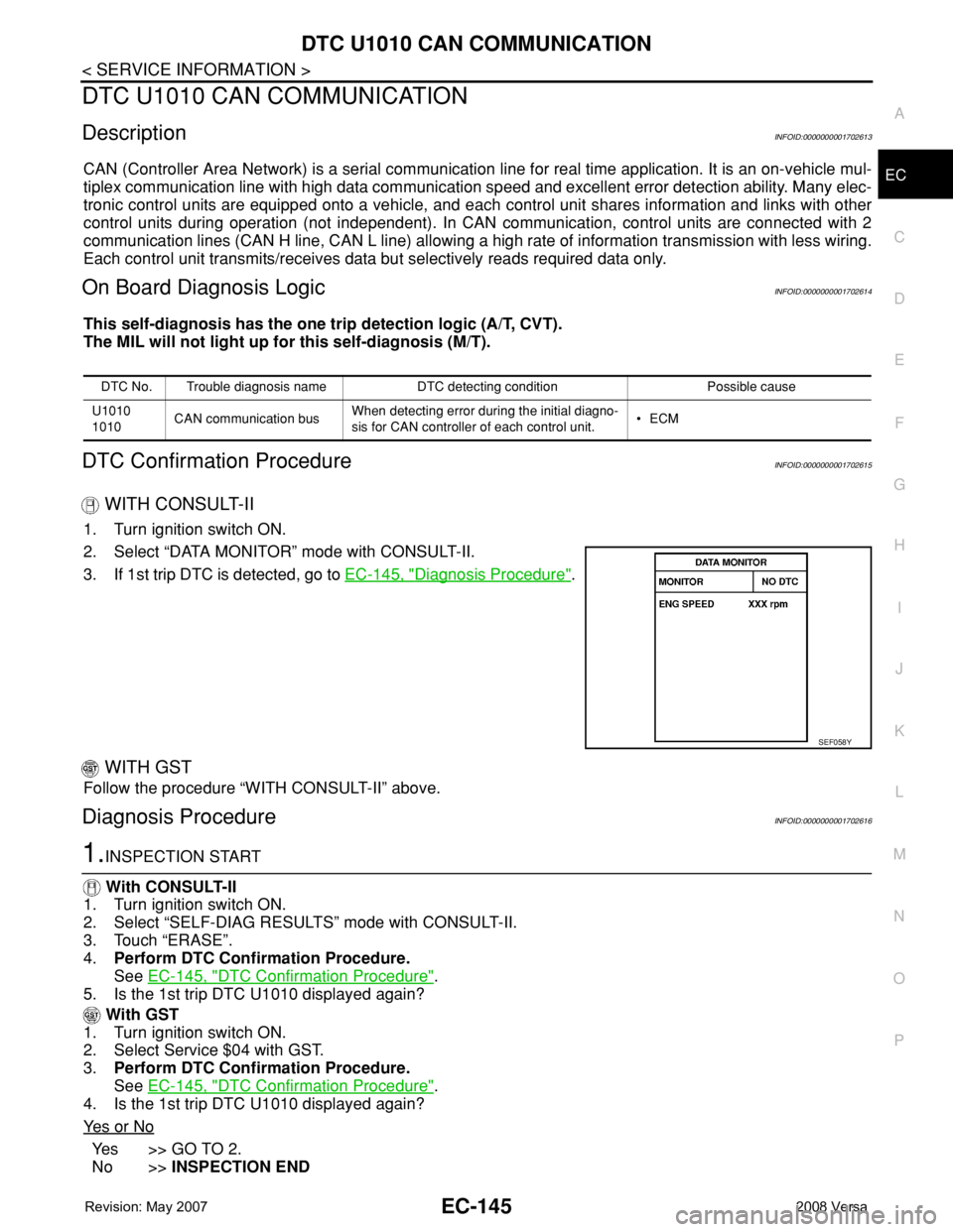
WITH CONSULT-II
1. Turn ignition switch ON.
2. Select “DATA MONITOR” mode with CONSULT-II.
3. If 1st trip DTC is detected, go to EC-145, "
Diagnosis Procedure".
WITH GST
Follow the procedure “WITH CONSULT-II” above.
Diagnosis ProcedureINFOID:0000000001702616
1.INSPECTION START
With CONSULT-II
1. Turn ignition switch ON.
2. Select “SELF-DIAG RESULTS” mode with CONSULT-II.
3. Touch “ERASE”.
4.Perform DTC Confirmation Procedure.
See EC-145, "
DTC Confirmation Procedure".
5. Is the 1st trip DTC U1010 displayed again?
With GST
1. Turn ignition switch ON.
2. Select Service $04 with GST.
3.Perform DTC Confirmation Procedure.
See EC-145, "
DTC Confirmation Procedure".
4. Is the 1st trip DTC U1010 displayed again?
Ye s o r N o
Yes >> GO TO 2.
No >>INSPECTION END
DTC No. Trouble diagnosis name DTC detecting condition Possible cause
U1010
1010CAN communication busWhen detecting error during the initial diagno-
sis for CAN controller of each control unit.•ECM
SEF058Y