2008 NISSAN TIIDA brake light
[x] Cancel search: brake lightPage 1752 of 2771
ENGINE ASSEMBLY
EM-75
< SERVICE INFORMATION >
C
D
E
F
G
H
I
J
K
L
MA
EM
N
P O
• When installation directions are specified, install parts according to the directions. Refer to EM-72, "Compo-
nent".
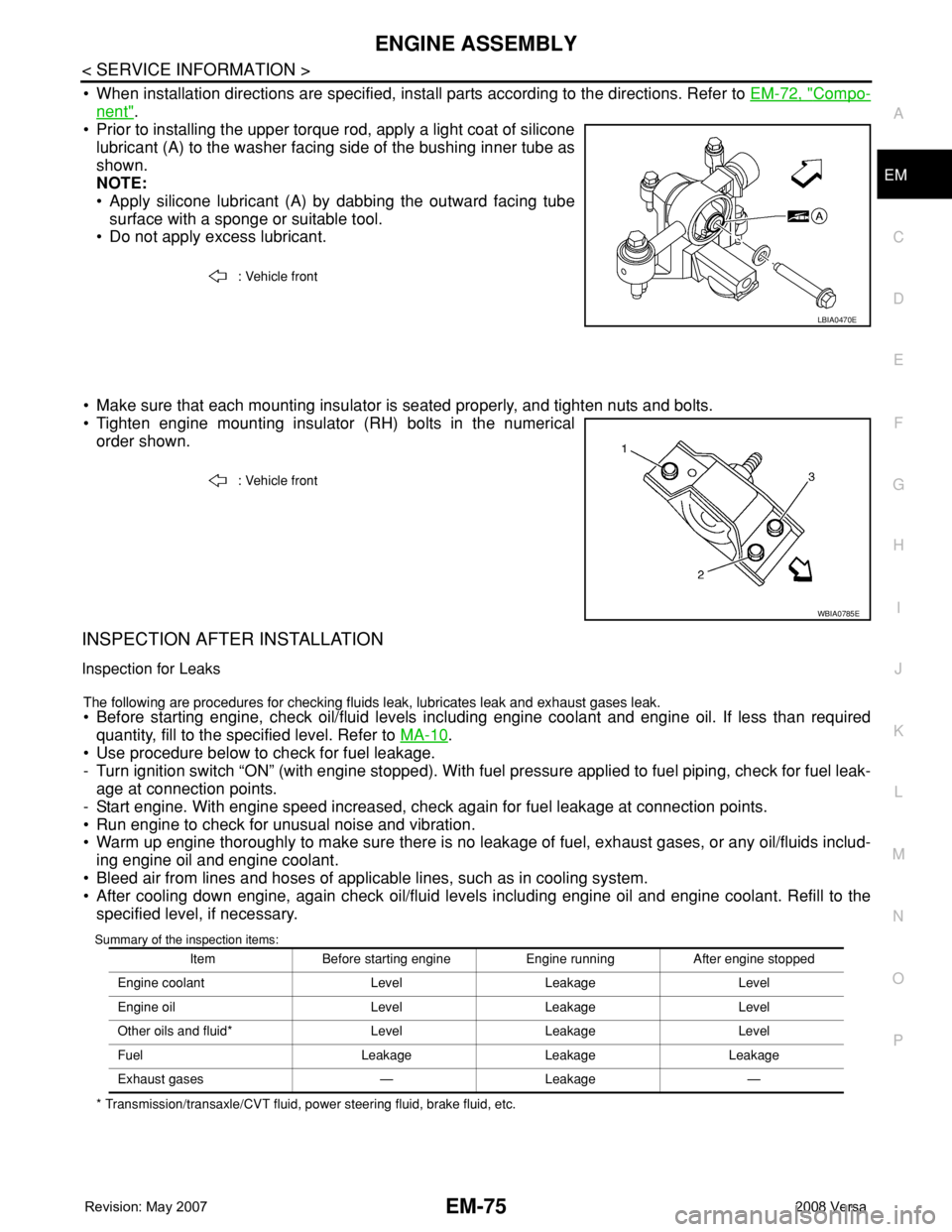
• Prior to installing the upper torque rod, apply a light coat of silicone
lubricant (A) to the washer facing side of the bushing inner tube as
shown.
NOTE:
• Apply silicone lubricant (A) by dabbing the outward facing tube
surface with a sponge or suitable tool.
• Do not apply excess lubricant.
• Make sure that each mounting insulator is seated properly, and tighten nuts and bolts.
• Tighten engine mounting insulator (RH) bolts in the numerical
order shown.
INSPECTION AFTER INSTALLATION
Inspection for Leaks
The following are procedures for checking fluids leak, lubricates leak and exhaust gases leak.
• Before starting engine, check oil/fluid levels including engine coolant and engine oil. If less than required
quantity, fill to the specified level. Refer to MA-10
.
• Use procedure below to check for fuel leakage.
- Turn ignition switch “ON” (with engine stopped). With fuel pressure applied to fuel piping, check for fuel leak-
age at connection points.
- Start engine. With engine speed increased, check again for fuel leakage at connection points.
• Run engine to check for unusual noise and vibration.
• Warm up engine thoroughly to make sure there is no leakage of fuel, exhaust gases, or any oil/fluids includ-
ing engine oil and engine coolant.
• Bleed air from lines and hoses of applicable lines, such as in cooling system.
• After cooling down engine, again check oil/fluid levels including engine oil and engine coolant. Refill to the
specified level, if necessary.
Summary of the inspection items:
* Transmission/transaxle/CVT fluid, power steering fluid, brake fluid, etc.: Vehicle front
LBIA0470E
: Vehicle front
WBIA0785E
Item Before starting engine Engine running After engine stopped
Engine coolant Level Leakage Level
Engine oil Level Leakage Level
Other oils and fluid* Level Leakage Level
Fuel Leakage Leakage Leakage
Exhaust gases — Leakage —
Page 1802 of 2771
FAX-6
< SERVICE INFORMATION >
FRONT WHEEL HUB AND KNUCKLE
2. Without disassembling the hydraulic lines, remove the torque member bolts using power tool. Then repo-
sition the torque member and brake caliper assembly aside with wire. Refer to BR-23
.
CAUTION:
Do not depress brake pedal while brake caliper is removed.
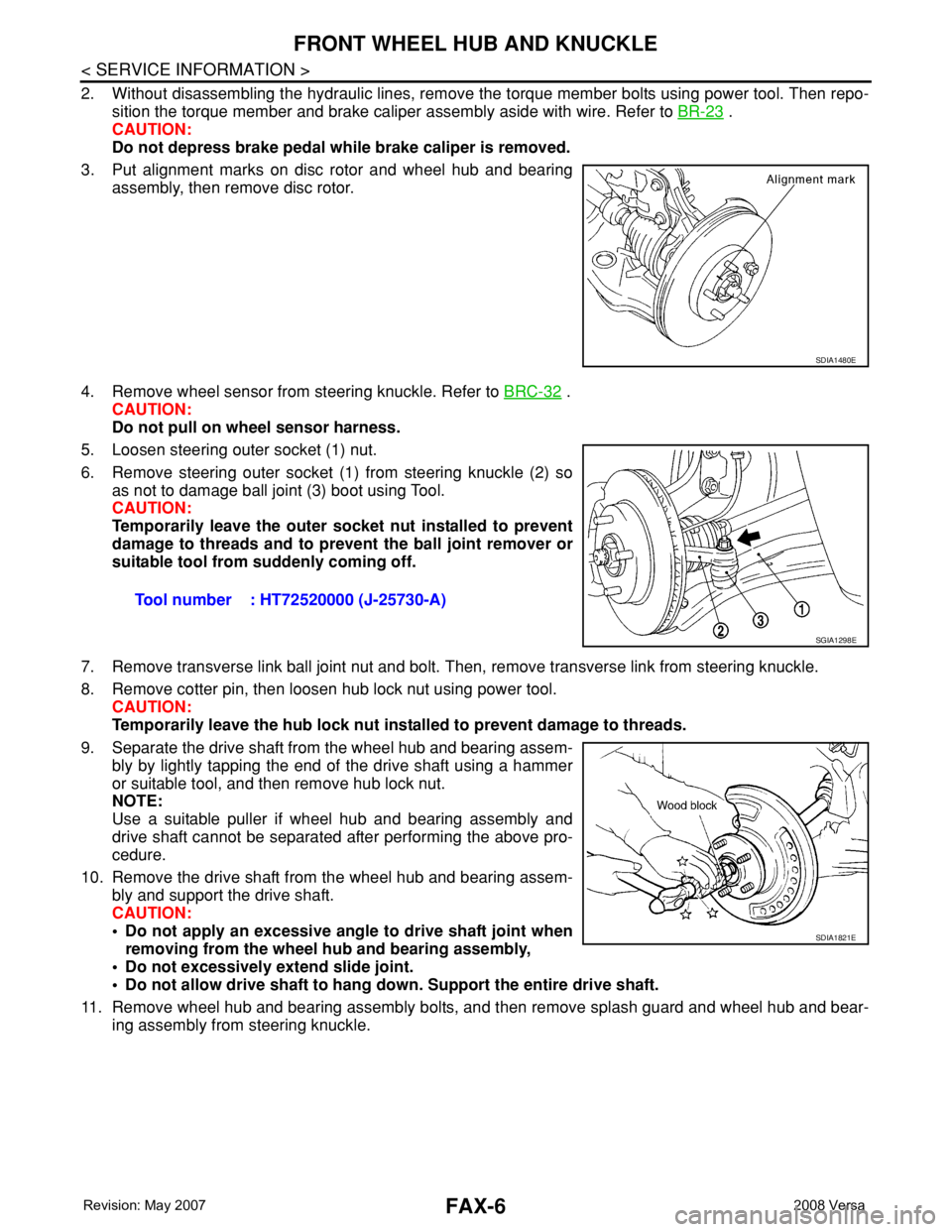
3. Put alignment marks on disc rotor and wheel hub and bearing
assembly, then remove disc rotor.
4. Remove wheel sensor from steering knuckle. Refer to BRC-32
.
CAUTION:
Do not pull on wheel sensor harness.
5. Loosen steering outer socket (1) nut.
6. Remove steering outer socket (1) from steering knuckle (2) so
as not to damage ball joint (3) boot using Tool.
CAUTION:
Temporarily leave the outer socket nut installed to prevent
damage to threads and to prevent the ball joint remover or
suitable tool from suddenly coming off.
7. Remove transverse link ball joint nut and bolt. Then, remove transverse link from steering knuckle.
8. Remove cotter pin, then loosen hub lock nut using power tool.
CAUTION:
Temporarily leave the hub lock nut installed to prevent damage to threads.
9. Separate the drive shaft from the wheel hub and bearing assem-
bly by lightly tapping the end of the drive shaft using a hammer
or suitable tool, and then remove hub lock nut.
NOTE:
Use a suitable puller if wheel hub and bearing assembly and
drive shaft cannot be separated after performing the above pro-
cedure.
10. Remove the drive shaft from the wheel hub and bearing assem-
bly and support the drive shaft.
CAUTION:
• Do not apply an excessive angle to drive shaft joint when
removing from the wheel hub and bearing assembly,
• Do not excessively extend slide joint.
• Do not allow drive shaft to hang down. Support the entire drive shaft.
11. Remove wheel hub and bearing assembly bolts, and then remove splash guard and wheel hub and bear-
ing assembly from steering knuckle.
SDIA1480E
Tool number : HT72520000 (J-25730-A)
SGIA1298E
SDIA1821E
Page 2149 of 2771

LT-12
< SERVICE INFORMATION >
HEADLAMP (FOR USA)
Note 1: Vehicles without daytime light system may display this item, but cannot monitor it.
ACTIVE TEST
Display Item List
SELF-DIAGNOSTIC RESULTS
Display Item List
CONSULT-III Function (IPDM E/R)INFOID:0000000001704370
CONSULT-III can display each diagnostic item using the diagnostic test modes shown following.
DATA MONITOR
All Items, Main Items, Select Item Menu
LIGHT SW 1ST "ON/OFF"Displays status (lighting switch 1st position: ON/Others: OFF) of lighting switch judged from lighting
switch signal.
PASSING SW "ON/OFF"Displays status (flash-to-pass switch: ON/Others: OFF) of flash-to-pass switch judged from lighting
switch signal.
FR FOG SW "ON/OFF"Displays status (front fog lamp switch: ON/Others: OFF) of front fog lamp switch judged from light-
ing switch signal.
DOOR SW - DR "ON/OFF"Displays status of the front door LH as judged from the front door switch LH signal. (Door is open:
ON/Door is closed: OFF)
DOOR SW - AS "ON/OFF"Displays status of the front door RH as judged from the front door switch RH signal. (Door is open:
ON/Door is closed: OFF)
DOOR SW - RR "ON/OFF"Displays status of the rear door as judged from the rear door switch (RH) signal. (Door is open:
ON/Door is closed: OFF)
DOOR SW - RL "ON/OFF"Displays status of the rear door as judged from the rear door switch (LH) signal. (Door is open: ON/
Door is closed: OFF)
BACK DOOR SW "ON/OFF"Displays status of the back door as judged from the back door switch signal. (Door is open: ON/
Door is closed: OFF)
TURN SIGNAL R "ON/OFF" Displays status (Turn right: ON/Others: OFF) as judged from lighting switch signal.
TURN SIGNAL L "ON/OFF" Displays status (Turn left: ON/Others: OFF) as judged from lighting switch signal.
ENGINE RUN
Note 1"ON/OFF" Displays status (Engine running: ON/Others: OFF) as judged from engine status signal.
PKB SW
Note 1"ON/OFF"Displays status (Parking brake switch: ON/Others: OFF) as judged from parking brake switch sig-
nal. Monitor item Contents
Test item Description
TAIL LAMP Allows tail lamp relay to operate by switching ON-OFF.
HEAD LAMP Allows headlamp relay (HI, LO) to operate by switching ON-OFF.
FR FOG LAMP Allows fog lamp relay to operate by switching ON-OFF.
Monitored item CONSULT-llI display Description
CAN communication CAN communication [U1000] Malfunction is detected in CAN communication.
CAN communication system CAN communication system 1 to 6 [U1000] Malfunction is detected in CAN system.
IPDM E/R diagnostic Mode Description
SELF-DIAG RESULTS Displays IPDM E/R self-diagnosis results.
DATA MONITOR Displays IPDM E/R input/output data in real time.
CAN DIAG SUPPORT MNTR The result of transmit/receive diagnosis of CAN communication can be read.
ACTIVE TEST Operation of electrical loads can be checked by sending drive signal to them.
Page 2162 of 2771
HEADLAMP (FOR CANADA) - DAYTIME LIGHT SYSTEM -
LT-25
< SERVICE INFORMATION >
C
D
E
F
G
H
I
J
L
MA
B
LT
N
O
P
HEADLAMP (FOR CANADA) - DAYTIME LIGHT SYSTEM -
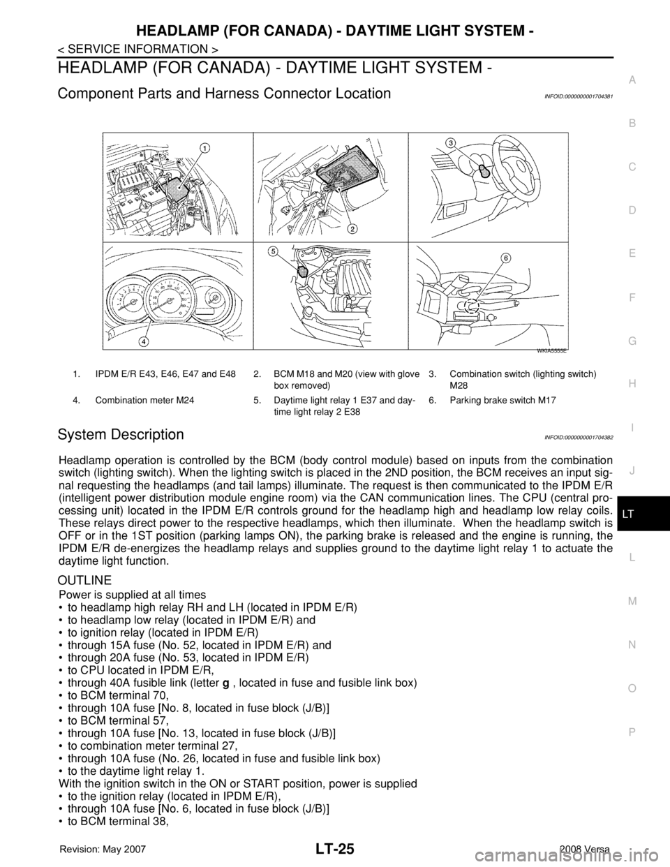
Component Parts and Harness Connector LocationINFOID:0000000001704381
System DescriptionINFOID:0000000001704382
Headlamp operation is controlled by the BCM (body control module) based on inputs from the combination
switch (lighting switch). When the lighting switch is placed in the 2ND position, the BCM receives an input sig-
nal requesting the headlamps (and tail lamps) illuminate. The request is then communicated to the IPDM E/R
(intelligent power distribution module engine room) via the CAN communication lines. The CPU (central pro-
cessing unit) located in the IPDM E/R controls ground for the headlamp high and headlamp low relay coils.
These relays direct power to the respective headlamps, which then illuminate. When the headlamp switch is
OFF or in the 1ST position (parking lamps ON), the parking brake is released and the engine is running, the
IPDM E/R de-energizes the headlamp relays and supplies ground to the daytime light relay 1 to actuate the
daytime light function.
OUTLINE
Power is supplied at all times
• to headlamp high relay RH and LH (located in IPDM E/R)
• to headlamp low relay (located in IPDM E/R) and
• to ignition relay (located in IPDM E/R)
• through 15A fuse (No. 52, located in IPDM E/R) and
• through 20A fuse (No. 53, located in IPDM E/R)
• to CPU located in IPDM E/R,
• through 40A fusible link (letter g , located in fuse and fusible link box)
• to BCM terminal 70,
• through 10A fuse [No. 8, located in fuse block (J/B)]
• to BCM terminal 57,
• through 10A fuse [No. 13, located in fuse block (J/B)]
• to combination meter terminal 27,
• through 10A fuse (No. 26, located in fuse and fusible link box)
• to the daytime light relay 1.
With the ignition switch in the ON or START position, power is supplied
• to the ignition relay (located in IPDM E/R),
• through 10A fuse [No. 6, located in fuse block (J/B)]
• to BCM terminal 38,
1. IPDM E/R E43, E46, E47 and E48 2. BCM M18 and M20 (view with glove
box removed)3. Combination switch (lighting switch)
M28
4. Combination meter M24 5. Daytime light relay 1 E37 and day-
time light relay 2 E386. Parking brake switch M17
WKIA5555E
Page 2163 of 2771
![NISSAN TIIDA 2008 Service Repair Manual LT-26
< SERVICE INFORMATION >
HEADLAMP (FOR CANADA) - DAYTIME LIGHT SYSTEM -
• through 10A fuse [No. 3, located in fuse block (J/B)]
• to combination meter terminal 28.
With the ignition switch in](/manual-img/5/57399/w960_57399-2162.png "NISSAN TIIDA 2008 Service Repair Manual LT-26
< SERVICE INFORMATION >
HEADLAMP (FOR CANADA) - DAYTIME LIGHT SYSTEM -
• through 10A fuse [No. 3, located in fuse block (J/B)]
• to combination meter terminal 28.
With the ignition switch in")
LT-26
< SERVICE INFORMATION >
HEADLAMP (FOR CANADA) - DAYTIME LIGHT SYSTEM -
• through 10A fuse [No. 3, located in fuse block (J/B)]
• to combination meter terminal 28.
With the ignition switch in the ACC or ON position, power is supplied
• through 10A fuse [No. 20, located in fuse block (J/B)]
• to BCM terminal 11.
Ground is supplied
• to BCM terminal 67 and
• to combination meter terminals 21, 22 and 23
• through grounds M57 and M61,
• to IPDM E/R terminals 39 and 59
• through grounds E15 and E24,
HEADLAMP OPERATION
Low Beam Operation
With the lighting switch in 2ND position, the BCM receives an input signal requesting the headlamps to illumi-
nate. This input signal is communicated to the IPDM E/R via the CAN communication lines. The CPU located
in the IPDM E/R controls the headlamp low relay coil, which when energized, directs power
• through 15A fuse (No. 41, located in IPDM E/R)
• through IPDM E/R terminal 54
• to daytime light relay 2 terminals 1 and 5 (energizing the relay),
• through daytime light relay 2 terminal 3
• to front combination lamp RH terminal 3, and
• through 15A fuse (No. 40, located in IPDM E/R)
• through IPDM E/R terminal 52
• to front combination lamp LH terminal 3.
Ground is supplied
• to front combination lamp LH terminal 2
• through grounds E15 and E24,
• to headlamp RH terminal 2 via
• daytime light relay 1 terminals 3 and 4
• through grounds E15 and E24.
With power and ground supplied, low beam headlamps illuminate.
High Beam/Flash-to-Pass Operation
With the lighting switch in 2ND position and high beam switch in the HIGH position, the BCM receives input
signal requesting the headlamp high beams to illuminate. The flash-to-pass feature can be used any time and
also sends a signal to the BCM. This input signal is communicated to the IPDM E/R and the combination
meter via the CAN communication lines. The CPU located in the IPDM E/R controls the headlamp high relay
coil, which when energized, directs power
• through 10A fuse (No. 34, located in IPDM E/R)
• through IPDM E/R terminal 56
• to front combination lamp RH terminal 1, and
• through 10A fuse (No. 35, located in IPDM E/R)
• through IPDM E/R terminal 55
• to front combination lamp LH terminal 1.
Ground is supplied
• to front combination lamp LH terminal 2
• through grounds E15 and E24, and
• to front combination lamp RH terminal 2 via
• daytime light relay 1 terminals 3 and 4
• through grounds E15 and E24.
With power and ground supplied, the high beam headlamps illuminate.
The BCM sends a signal to the combination meter requesting the high beam indicator lamp to turn ON.
Daytime Light System Operation
With the lighting switch in the OFF or 1ST position (parking lamps ON), the BCM receives inputs requesting
the headlights off. If the parking brake is released and the engine is running, the BCM then sends a signal, via
the CAN communication lines, requesting the IPDM E/R to activate the daytime light system. The CPU located
in the IPDM E/R controls the daytime light relay 1 coil, which when energized, directs power
• from daytime light relay 1 terminal 3
• to front combination lamp RH terminal 2,
• through front combination lamp RH high beam terminal 1
Page 2171 of 2771
LT-34
< SERVICE INFORMATION >
HEADLAMP (FOR CANADA) - DAYTIME LIGHT SYSTEM -
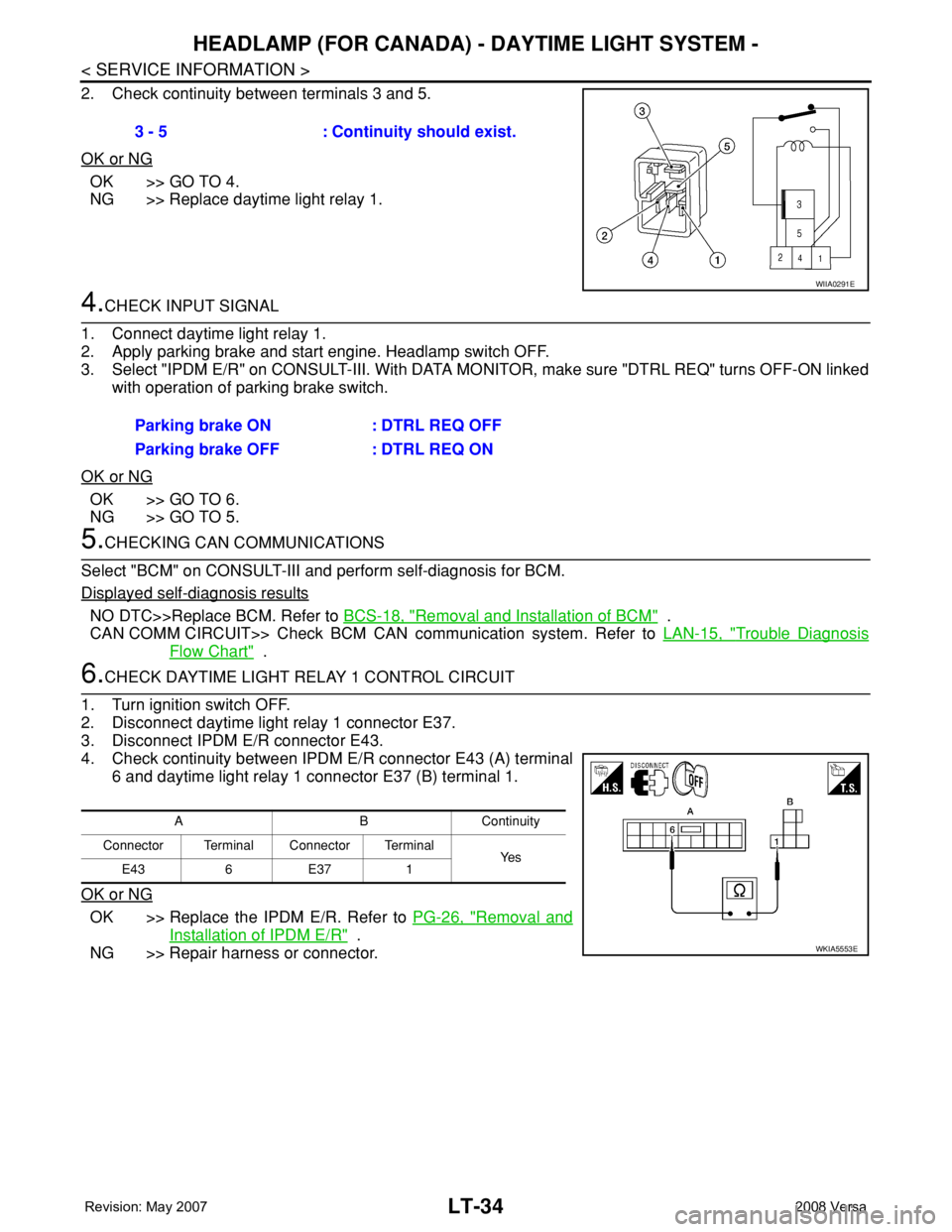
2. Check continuity between terminals 3 and 5.
OK or NG
OK >> GO TO 4.
NG >> Replace daytime light relay 1.
4.CHECK INPUT SIGNAL
1. Connect daytime light relay 1.
2. Apply parking brake and start engine. Headlamp switch OFF.
3. Select "IPDM E/R" on CONSULT-III. With DATA MONITOR, make sure "DTRL REQ" turns OFF-ON linked
with operation of parking brake switch.
OK or NG
OK >> GO TO 6.
NG >> GO TO 5.
5.CHECKING CAN COMMUNICATIONS
Select "BCM" on CONSULT-III and perform self-diagnosis for BCM.
Displayed self-diagnosis results
NO DTC>>Replace BCM. Refer to BCS-18, "Removal and Installation of BCM" .
CAN COMM CIRCUIT>> Check BCM CAN communication system. Refer to LAN-15, "
Trouble Diagnosis
Flow Chart" .
6.CHECK DAYTIME LIGHT RELAY 1 CONTROL CIRCUIT
1. Turn ignition switch OFF.
2. Disconnect daytime light relay 1 connector E37.
3. Disconnect IPDM E/R connector E43.
4. Check continuity between IPDM E/R connector E43 (A) terminal
6 and daytime light relay 1 connector E37 (B) terminal 1.
OK or NG
OK >> Replace the IPDM E/R. Refer to PG-26, "Removal and
Installation of IPDM E/R" .
NG >> Repair harness or connector. 3 - 5 : Continuity should exist.
WIIA0291E
Parking brake ON : DTRL REQ OFF
Parking brake OFF : DTRL REQ ON
ABContinuity
Connector Terminal Connector Terminal
Ye s
E43 6 E37 1
WKIA5553E
Page 2491 of 2771

PG-58
< SERVICE INFORMATION >
HARNESS
Wiring Diagram Codes (Cell Codes)
INFOID:0000000001704709
Use the chart below to find out what each wiring diagram code stands for.
Refer to the wiring diagram code in the alphabetical index to find the location (page number) of each wiring
diagram.
D3 D404 W/3 : Rear wiper motor
D4 D405 W/4 : Back door lock assembly
D4 D406 W/2 : Back door request switch
E2 D407 W/2 : High mounted stop lamp
D4 D408 BR/2 : Back door opener switch
E4 D409 B/1 : Condenser-1
C2 D410 — : Body ground
E3 D411 B/1 : Condenser-1
E1 D412 B/1 : Rear window defogger (+)
C2 D413 B/1 : Rear window defogger (-)
F3 D414 — : Body ground
Code Section Wiring Diagram Name
ABS BRC Anti-lock Brake System
A/C,M MTC Manual Air Conditioner
APPS1 EC Accelerator Pedal Position Sensor
A/F EC Air Fuel Ratio Sensor 1
A/FH EC Air Fuel Ratio Sensor 1 Heater
APPS2 EC Accelerator Pedal Position Sensor
APPS3 EC Accelerator Pedal Position Sensor
ASC/BS EC ASCD Brake Switch
ASC/SW EC ASCD Steering Switch
ASCBOF EC ASCD Brake Switch
ASCIND EC ASCD Indicator
AT/IND DI A/T Indicator Lamp
AUDIO AV Audio
BACK/L LT Back-up Lamp
BA/FTS AT A/T Fluid Temperature Sensor and TCM Power Supply
B/DOOR BL Back Door Opener
BRK/SW EC Brake Switch
CAN AT CAN Communication Line
CAN CVT CAN Communication Line
CAN EC CAN Communication Line
CAN LAN CAN System
CHARGE SC Charging System
CHIME DI Warning Chime
COOL/F EC Cooling Fan Control
COMBSW LT Combination Switch
CVTIND DI CVT Indicator Lamp
D/LOCK BL Power Door Lock
DEF GW Rear Window Defogger
DTRL LT Headlamp - With Daytime Light System
ECTS EC Engine Coolant Temperature Sensor
ENGSS AT Engine Speed Signal
EPS STC Electronic Controlled Power Steering
ETC1 EC Electric Throttle Control Function
Page 2512 of 2771
PS-6
< SERVICE INFORMATION >
STEERING WHEEL
STEERING WHEEL
On-Vehicle Inspection and ServiceINFOID:0000000001703859
CHECKING CONDITION OF INSTALLATION
• Check installation conditions of steering gear assembly, front suspension assembly, axle and steering col-
umn assembly.
• Check if movement exists when steering wheel is moved up and down, to the left and right and to the axial
direction.
• Check steering gear assembly mounting bolts and nuts for looseness. Refer to PS-12, "
Removal and Instal-
lation" .
CHECKING STEERING WHEEL PLAY
• Turn steering wheel so that front wheels come to the straight-ahead position. Start engine and lightly turn
steering wheel to the left and right until front wheels start to move. Measure steering wheel movement on the
outer circumference.
• When the measurement value is outside the standard value, check backlash for each joint of steering col-
umn assembly and installation condition of steering gear assembly.
CHECKING NEUTRAL POSITION STEERING WHEEL
• Make sure that steering gear assembly, steering column assembly and steering wheel are installed in the
correct position.
• Perform neutral position inspection after wheel alignment. Refer to RSU-2, "
Precaution for Supplemental
Restraint System (SRS) "AIR BAG" and "SEAT BELT PRE-TENSIONER"" .
• Set vehicle to the straight-ahead position and confirm steering wheel is in the neutral position.
• Loosen outer socket lock nut and turn inner socket to left and right equally to make fine adjustments if steer-
ing wheel is not in the neutral position.
CHECKING STEERING WHEEL TURNING FORCE
1. Park vehicle on a level and dry surface, set parking brake.
2. Start engine.
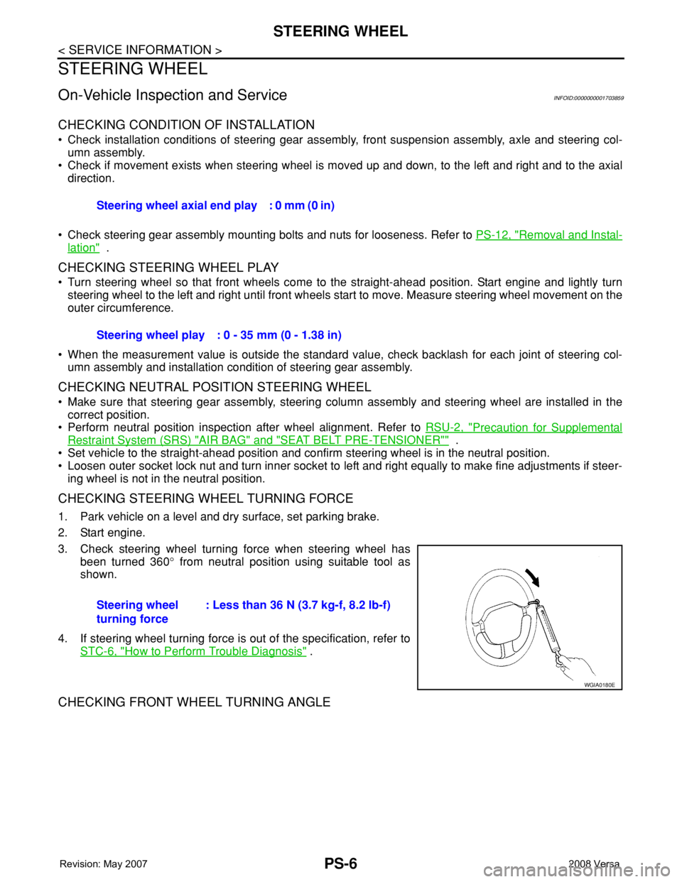
3. Check steering wheel turning force when steering wheel has
been turned 360° from neutral position using suitable tool as
shown.
4. If steering wheel turning force is out of the specification, refer to
STC-6, "
How to Perform Trouble Diagnosis" .
CHECKING FRONT WHEEL TURNING ANGLE
Steering wheel axial end play : 0 mm (0 in)
Steering wheel play : 0 - 35 mm (0 - 1.38 in)
Steering wheel
turning force: Less than 36 N (3.7 kg-f, 8.2 lb-f)
WGIA0180E