2008 NISSAN TIIDA brake light
[x] Cancel search: brake lightPage 770 of 2771
![NISSAN TIIDA 2008 Service Repair Manual SYSTEM DESCRIPTION
BRC-5
< SERVICE INFORMATION >[ABS]
C
D
E
G
H
I
J
K
L
MA
B
BRC
N
O
P
SYSTEM DESCRIPTION
System ComponentINFOID:0000000001703825
ABS FunctionINFOID:0000000001703826
• The Anti-Lock](/manual-img/5/57399/w960_57399-769.png "NISSAN TIIDA 2008 Service Repair Manual SYSTEM DESCRIPTION
BRC-5
< SERVICE INFORMATION >[ABS]
C
D
E
G
H
I
J
K
L
MA
B
BRC
N
O
P
SYSTEM DESCRIPTION
System ComponentINFOID:0000000001703825
ABS FunctionINFOID:0000000001703826
• The Anti-Lock")
SYSTEM DESCRIPTION
BRC-5
< SERVICE INFORMATION >[ABS]
C
D
E
G
H
I
J
K
L
MA
B
BRC
N
O
P
SYSTEM DESCRIPTION
System ComponentINFOID:0000000001703825
ABS FunctionINFOID:0000000001703826
• The Anti-Lock Brake System detects wheel revolution while braking and improves handling stability during
sudden braking by electrically preventing wheel lockup. Maneuverability is also improved for avoiding obsta-
cles during emergency braking.
• If the electrical system malfunctions, the Fail-Safe function is activated, the ABS becomes inoperative and
the ABS warning lamp turns on.
• The electrical system can be diagnosed using CONSULT-III.
• During ABS operation, the brake pedal may vibrate lightly and a mechanical noise may be heard. This is
normal.
• Just after starting the vehicle, the brake pedal may vibrate or motor operating noises may be heard from the
engine compartment. This is normal due to the self check operation.
• Stopping distance may be longer than that of vehicles without ABS when vehicle drives on rough, gravel, or
snow-covered (fresh, deep snow) roads.
EBD FunctionINFOID:0000000001703827
• Electronic Brake Distribution is a function that detects subtle slippages between the front and rear wheels
during braking, and it improves handling stability by electronically controlling the brake fluid pressure which
results in reduced rear wheel slippage.
• If the electrical system malfunctions, the Fail-Safe function is activated, the EBD and ABS become inopera-
tive, and the ABS warning lamp and brake warning lamp are turned on.
• The electrical system can be diagnosed using CONSULT-III.
• During EBD operation, the brake pedal may vibrate lightly and a mechanical noise may be heard. This is
normal.
• Just after starting the vehicle, the brake pedal may vibrate or motor operating noises may be heard from the
engine compartment. This is normal due to the self check operation.
Fail-Safe FunctionINFOID:0000000001703828
CAUTION:
If the Fail-Safe function is activated, perform the Self Diagnosis for ABS system.
ABS/EBD SYSTEM
In case of an electrical malfunction with the ABS, the ABS warning lamp will turn on. In case of an electrical
malfunction with the EBD system, the brake warning lamp and the ABS warning lamp will turn on.
The system will revert to one of the following conditions of the Fail-Safe function.
1. For ABS malfunction, only the EBD is operative and the condition of the vehicle is the same condition of
vehicles without ABS system.
WFIA0118E
Page 847 of 2771

CVT-8
< SERVICE INFORMATION >
PRECAUTIONS
• Be sure to turn the ignition switch OFF and disconnect the battery cable from the negative terminal
before any repair or inspection work. The open/short circuit of related switches, sensors, solenoid
valves, etc. will cause the MIL to light up.
• Be sure to connect and lock the connectors securely after work. A loose (unlocked) connector will
cause the MIL to light up due to an open circuit. (Be sure the connector is free from water, grease,
dirt, bent terminals, etc.)
• Be sure to route and secure the harnesses properly after work. Interference of the harness with a
bracket, etc. may cause the MIL to light up due to a short circuit.
• Be sure to connect rubber tubes properly after work. A misconnected or disconnected rubber tube
may cause the MIL to light up due to a malfunction of the EVAP system or fuel injection system, etc.
• Be sure to erase the unnecessary malfunction information (repairs completed) from the TCM and
ECM before returning the vehicle to the customer.
Service After Replacing TCM and Transaxle AssemblyINFOID:0000000001703427
SERVICE AFTER REPLACING TCM AND TRANSAXLE ASSEMBLY
Perform the applicable service in the following sheet when replacing TCM or transaxle assembly
CAUTION:
• Do not start the engine until the service is completed.
• “A/T C/U POWER SUPPLY [P1701]” may be indicated soon after replacing TCM or transaxle assem-
bly (after erasing the memory at the pattern B). Restart the self-diagnosis after erasing the self-diag-
nosis result. Check that no error is detected.
NOTE:
Old unit means that the unit has been already used for another vehicle.
PATTERN A
1. Shift the selector lever to “P” position after replacing TCM. Turn the ignition switch ON.
2. Check that the shift position indicator in the combination meter turns ON (It indicates approximately 1 or 2
seconds after turning the ignition switch ON.)
• Check the following items if the shift position indicator does not turn ON. Repair or replace the shift posi-
tion indicator if necessary.
- The harness between TCM and ROM ASSY in the transaxle assembly is open or short.
- Cable disconnected, loosen, or bent from the connector housing.
PATTERN B
1. Turn the ignition switch ON after replacing each part.
2. Start engine.
CAUTION:
Do not start the driving.
3. Touch CONSULT-III screen in the order of “START (NISSAN BASED VHCL)”, “TRANSMISSION”, “DATA
MONITOR”, and “MAIN SIGNALS”.
4. Warm up the transaxle assembly until “ATFTEMPCOUNT” indicates 47 [approximately 20°C (68°F)] or
more. Turn the ignition switch OFF.
5. Turn the ignition switch ON.
CAUTION:
Do not start engine.
6. Select “SELF-DIAG RESULTS”.
7. Shift the selector lever to “R” position.
8. Depress slightly the accelerator pedal (Pedal angle: 2/8) while depressing the brake pedal.
9. Perform “ERASE”.
TCM CVT assemblyService pattern
Replace the new unit. Do not replace the unit. "PATTERN A"
Do not replace the unit. Replace the new or old unit.
"PATTERN B"
Replace the old unit.Do not replace the unit.
Replace the new or old unit.
Replace the new unit. Replace the new or old unit. "PATTERN C"
Page 1009 of 2771

CVT-170
< SERVICE INFORMATION >
SHIFT CONTROL SYSTEM
• When installing the control cable (1) to the control device assembly
(2), make sure that the control cable (1) is fully pressed in with the
ribbed surface (A) facing downward from the vehicle.
: Vehicle front
• After installation is completed, adjust and check the CVT position.
Refer to CVT-171, "
Adjustment of CVT Position" and CVT-171,
"Checking of CVT Position".
Control Device Disassembly and AssemblyINFOID:0000000001703680
DISASSEMBLY
NOTE:
Refer to CVT-167, "
Removal and Installation" to disassemble.
1. Remove selector lever knob from control device assembly. Refer to CVT-170, "
Selector Lever Knob
Removal and Installation".
2. Remove position lamp from position indicator plate (1).
3. Insert a flat-bladed screwdriver to (A) (at 4 locations) as shown,
and bend each hook slightly to raise position indicator plate (1)
and remove from control device assembly (2).
4. Remove bracket from control device assembly (2).
5. Remove CVT device harness connector from control device
assembly (2).
6. Release tabs (A) on shift lock solenoid and park position switch
assembly from hooks (B) on control device assembly to shift
lock solenoid and park position switch assembly.
ASSEMBLY
Assembly is in the reverse order of disassembly.
Selector Lever Knob Removal and InstallationINFOID:0000000001703681
REMOVAL
CAUTION:
Make sure that parking brake is applied before removal/installation.
SCIA6253E
SCIA6969E
SCIA6977E
Page 1022 of 2771

DI-1
ELECTRICAL
C
D
E
F
G
H
I
J
L
M
SECTION DI
A
B
DI
N
O
P
CONTENTS
DRIVER INFORMATION SYSTEM
SERVICE INFORMATION ............................2
PRECAUTION .....................................................2
Precaution for Supplemental Restraint System
(SRS) "AIR BAG" and "SEAT BELT PRE-TEN-
SIONER" ...................................................................
2
PREPARATION ...................................................3
Commercial Service Tool ..........................................3
COMBINATION METERS ...................................4
Component Parts and Harness Connector Loca-
tion ............................................................................
4
System Description ...................................................4
Arrangement of Combination Meter ..........................6
Internal Circuit ...........................................................7
Wiring Diagram - METER - .......................................8
Combination Meter Harness Connector Terminal
Layout .....................................................................
10
Terminal and Reference Value for Combination
Meter .......................................................................
10
Self-Diagnosis Mode of Combination Meter ............11
CONSULT-III Function (METER/M&A) ...................13
Trouble Diagnosis ...................................................14
Symptom Chart .......................................................15
Power Supply and Ground Circuit Inspection .........15
Vehicle Speed Signal Inspection .............................16
Engine Speed Signal Inspection .............................17
Fuel Level Sensor Signal Inspection .......................17
Fuel Gauge Fluctuates, Indicates Wrong Value, or
Varies ......................................................................
19
Fuel Gauge Does Not Move to Full-position ...........19
DTC [U1000] CAN Communication Circuit .............19
Electrical Component Inspection .............................19
Removal and Installation .........................................20
WARNING LAMPS .............................................21
Schematic ................................................................21
Wiring Diagram - WARN - .......................................22
Oil Pressure Warning Lamp Stays Off (Ignition
Switch ON) ..............................................................
30
Oil Pressure Warning Lamp Does Not Turn Off
(Oil Pressure Is Normal) ..........................................
32
Component Inspection .............................................32
A/T INDICATOR ................................................34
System Description ..................................................34
Wiring Diagram - AT/IND - .......................................35
A/T Indicator Does Not Illuminate ............................36
CVT INDICATOR ...............................................38
System Description ..................................................38
Wiring Diagram - CVTIND - .....................................38
CVT Indicator Does Not Illuminate ..........................39
WARNING CHIME .............................................41
Component Parts and Harness Connector Loca-
tion ...........................................................................
41
System Description ..................................................41
Wiring Diagram - CHIME - .......................................44
Terminal and Reference Value for BCM ..................45
CONSULT-III Function (BCM) .................................45
Trouble Diagnosis ....................................................46
Combination Meter Buzzer Circuit Inspection .........47
Front Door Switch LH Signal Inspection ..................48
Key Switch Signal Inspection (Without Intelligent
Key) .........................................................................
49
Key Switch and Ignition Knob Switch Signal In-
spection (With Intelligent Key, When Mechanical
Key Is Used) ............................................................
50
Lighting Switch Signal Inspection ............................52
Parking Brake Switch Signal Inspection ..................52
Electrical Component Inspection .............................53
Page 1062 of 2771
WARNING CHIME
DI-41
< SERVICE INFORMATION >
C
D
E
F
G
H
I
J
L
MA
B
DI
N
O
P
WARNING CHIME
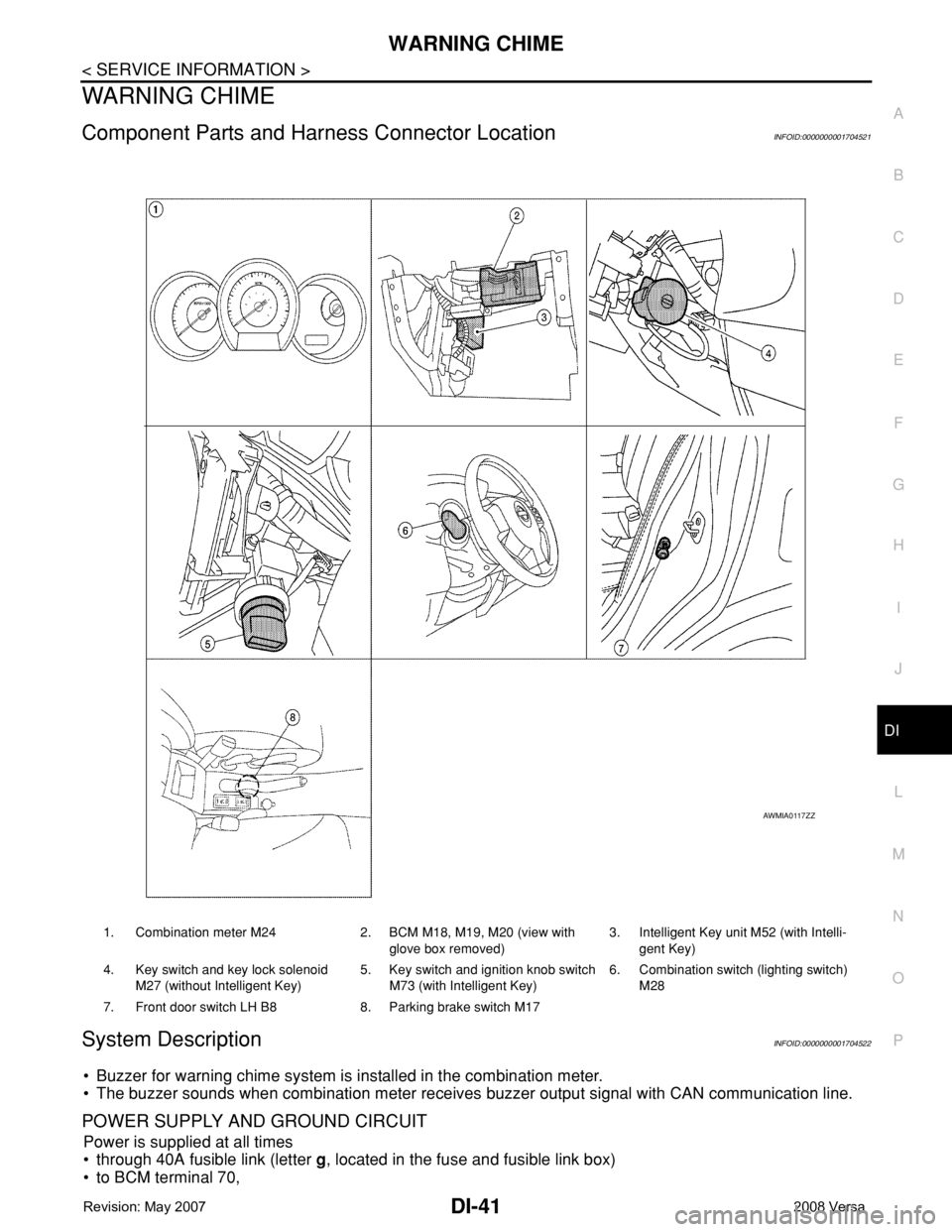
Component Parts and Harness Connector LocationINFOID:0000000001704521
System DescriptionINFOID:0000000001704522
• Buzzer for warning chime system is installed in the combination meter.
• The buzzer sounds when combination meter receives buzzer output signal with CAN communication line.
POWER SUPPLY AND GROUND CIRCUIT
Power is supplied at all times
• through 40A fusible link (letter g, located in the fuse and fusible link box)
• to BCM terminal 70,
1. Combination meter M24 2. BCM M18, M19, M20 (view with
glove box removed)3. Intelligent Key unit M52 (with Intelli-
gent Key)
4. Key switch and key lock solenoid
M27 (without Intelligent Key)5. Key switch and ignition knob switch
M73 (with Intelligent Key)6. Combination switch (lighting switch)
M28
7. Front door switch LH B8 8. Parking brake switch M17
AWMIA0117ZZ
Page 1064 of 2771
WARNING CHIME
DI-43
< SERVICE INFORMATION >
C
D
E
F
G
H
I
J
L
MA
B
DI
N
O
P
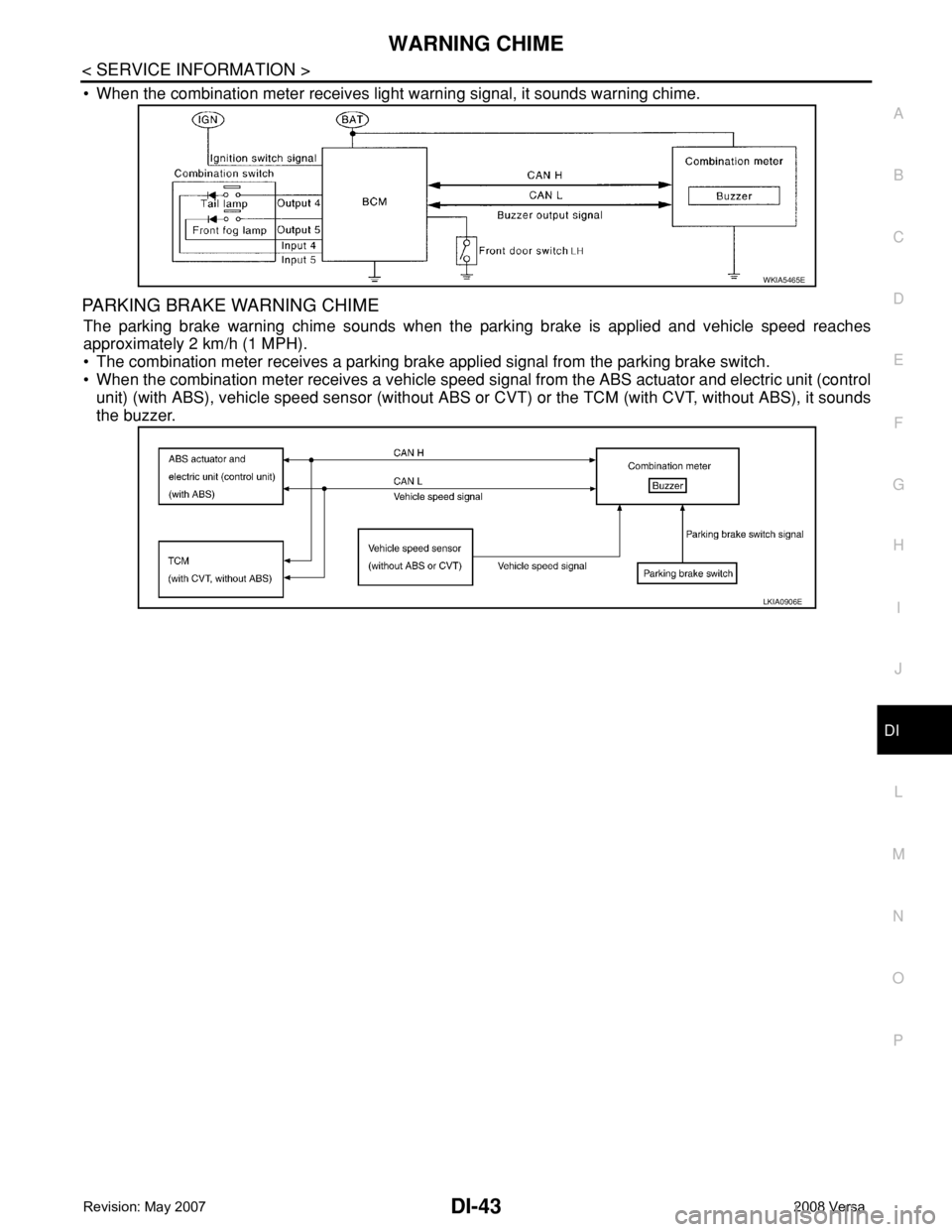
• When the combination meter receives light warning signal, it sounds warning chime.
PARKING BRAKE WARNING CHIME
The parking brake warning chime sounds when the parking brake is applied and vehicle speed reaches
approximately 2 km/h (1 MPH).
• The combination meter receives a parking brake applied signal from the parking brake switch.
• When the combination meter receives a vehicle speed signal from the ABS actuator and electric unit (control
unit) (with ABS), vehicle speed sensor (without ABS or CVT) or the TCM (with CVT, without ABS), it sounds
the buzzer.
WKIA5465E
LKIA0906E
Page 1068 of 2771
WARNING CHIME
DI-47
< SERVICE INFORMATION >
C
D
E
F
G
H
I
J
L
MA
B
DI
N
O
P
1.CHECK BCM
Perform self-diagnosis of BCM. Refer to DI-45, "
CONSULT-III Function (BCM)".
Self
-diagnostic results content
No malfunction detected>>GO TO 2.
Malfunction detected>> Check applicable parts, and repair or replace corresponding parts.
2.CHECK COMBINATION METER
Perform self-diagnosis of combination meter. Refer to DI-13, "
CONSULT-III Function (METER/M&A)".
Self
-diagnostic results content
No malfunction detected>> Inspection End.
Malfunction detected>> Check applicable parts, and repair or replace corresponding parts.
SYMPTOM CHART
Combination Meter Buzzer Circuit InspectionINFOID:0000000001704527
1.CHECK CHIME OPERATION
1. Select “BUZZER” of “BCM” on CONSULT-III.
2. Perform “LIGHT WARN ALM” or “IGN KEY WARN ALM” of “ACTIVE TEST”.
Does chime sound?
YES >> Combination meter buzzer circuit is OK. Return to DI-46, "Trouble Diagnosis".
NO >> GO TO 2.
2.CHECK COMBINATION METER INPUT SIGNAL
1. Select “METER/M&A” on CONSULT-III.
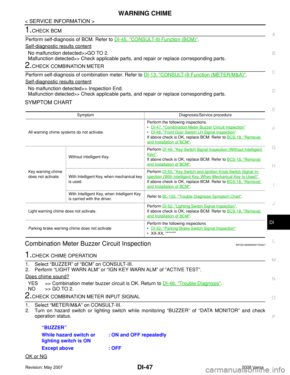
2. Turn on hazard switch or lighting switch while monitoring “BUZZER” of “DATA MONITOR” and check
operation status.
OK or NG
Symptom Diagnoses/Service procedure
All warning chime systems do not activate.Perform the following inspections.
•DI-47, "
Combination Meter Buzzer Circuit Inspection"
•DI-48, "Front Door Switch LH Signal Inspection"
If above check is OK, replace BCM. Refer to BCS-18, "Removal
and Installation of BCM".
Key warning chime
does not activate.Without Intelligent Key.Perform DI-49, "
Key Switch Signal Inspection (Without Intelligent
Key)".
If above check is OK, replace BCM. Refer to BCS-18, "
Removal
and Installation of BCM".
With Intelligent Key, when mechanical key
is used.Perform DI-50, "
Key Switch and Ignition Knob Switch Signal In-
spection (With Intelligent Key, When Mechanical Key Is Used)".
If above check is OK, replace BCM. Refer to BCS-18, "
Removal
and Installation of BCM".
With Intelligent Key, when Intelligent Key
is carried with the driver.Refer to BL-103, "
Trouble Diagnosis Symptom Chart".
Light warning chime does not activate.Perform DI-52, "
Lighting Switch Signal Inspection".
If above check is OK, replace BCM. Refer to BCS-18, "
Removal
and Installation of BCM".
Parking brake warning chime does not activatePerform the following inspections
•DI-52, "
Parking Brake Switch Signal Inspection"
• XX-XX, "*****"
“BUZZER”
While hazard switch or
lighting switch is ON : ON and OFF repeatedly
Except above : OFF
Page 1073 of 2771
DI-52
< SERVICE INFORMATION >
WARNING CHIME
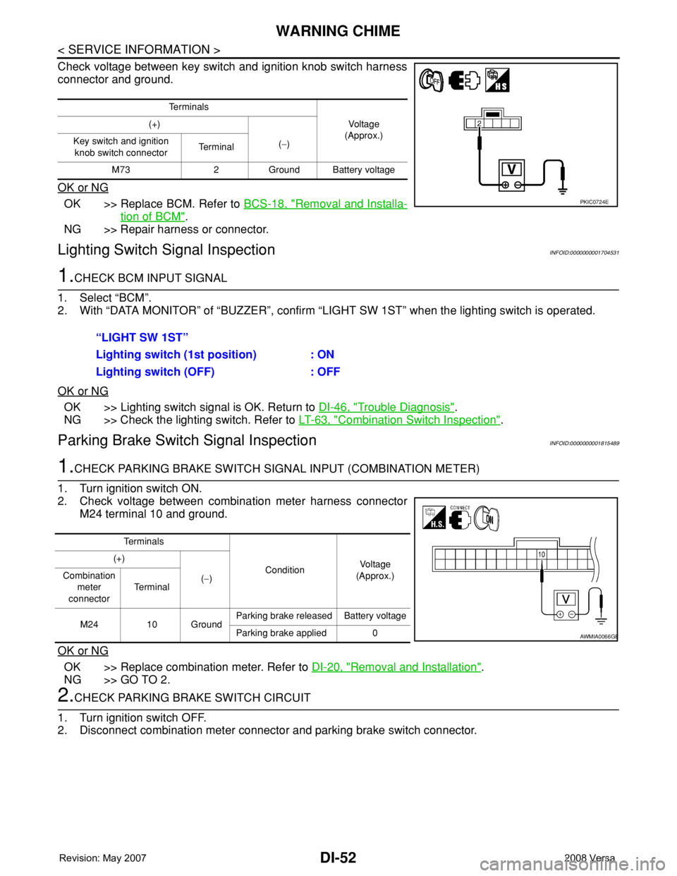
Check voltage between key switch and ignition knob switch harness
connector and ground.
OK or NG
OK >> Replace BCM. Refer to BCS-18, "Removal and Installa-
tion of BCM".
NG >> Repair harness or connector.
Lighting Switch Signal InspectionINFOID:0000000001704531
1.CHECK BCM INPUT SIGNAL
1. Select “BCM”.
2. With “DATA MONITOR” of “BUZZER”, confirm “LIGHT SW 1ST” when the lighting switch is operated.
OK or NG
OK >> Lighting switch signal is OK. Return to DI-46, "Trouble Diagnosis".
NG >> Check the lighting switch. Refer to LT-63, "
Combination Switch Inspection".
Parking Brake Switch Signal InspectionINFOID:0000000001815489
1.CHECK PARKING BRAKE SWITCH SIGNAL INPUT (COMBINATION METER)
1. Turn ignition switch ON.
2. Check voltage between combination meter harness connector
M24 terminal 10 and ground.
OK or NG
OK >> Replace combination meter. Refer to DI-20, "Removal and Installation".
NG >> GO TO 2.
2.CHECK PARKING BRAKE SWITCH CIRCUIT
1. Turn ignition switch OFF.
2. Disconnect combination meter connector and parking brake switch connector.
Te r m i n a l s
Vo l ta g e
(Approx.) (+)
(−) Key switch and ignition
knob switch connector Te r m i n a l
M73 2 Ground Battery voltage
PKIC0724E
“LIGHT SW 1ST”
Lighting switch (1st position) : ON
Lighting switch (OFF) : OFF
Te r m i n a l s
ConditionVoltag e
(Approx.) (+)
(−) Combination
meter
connectorTe r m i n a l
M24 10 GroundParking brake released Battery voltage
Parking brake applied 0
AWMIA0066GB