Page 1154 of 2771

EC-80
< SERVICE INFORMATION >
BASIC SERVICE PROCEDURE
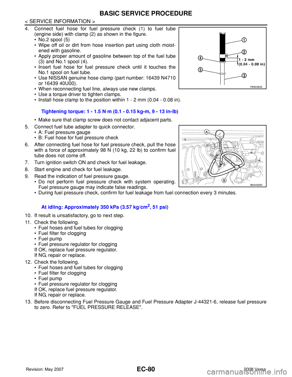
4. Connect fuel hose for fuel pressure check (1) to fuel tube
(engine side) with clamp (2) as shown in the figure.
• No.2 spool (5)
• Wipe off oil or dirt from hose insertion part using cloth moist-
ened with gasoline.
• Apply proper amount of gasoline between top of the fuel tube
(3) and No.1 spool (4).
• Insert fuel hose for fuel pressure check until it touches the
No.1 spool on fuel tube.
• Use NISSAN genuine hose clamp (part number: 16439 N4710
or 16439 40U00).
• When reconnecting fuel line, always use new clamps.
• Use a torque driver to tighten clamps.
• Install hose clamp to the position within 1 - 2 mm (0.04 - 0.08 in).
• Make sure that clamp screw does not contact adjacent parts.
5. Connect fuel tube adapter to quick connector.
• A: Fuel pressure gauge
• B: Fuel hose for fuel pressure check
6. After connecting fuel hose for fuel pressure check, pull the hose
with a force of approximately 98 N (10 kg, 22 lb) to confirm fuel
tube does not come off.
7. Turn ignition switch ON and check for fuel leakage.
8. Start engine and check for fuel leakage.
9. Read the indication of fuel pressure gauge.
• Do not perform fuel pressure check with system operating.
Fuel pressure gauge may indicate false readings.
• During fuel pressure check, confirm for fuel leakage from fuel connection every 3 minutes.
10. If result is unsatisfactory, go to next step.
11. Check the following.
• Fuel hoses and fuel tubes for clogging
• Fuel filter for clogging
• Fuel pump
• Fuel pressure regulator for clogging
If OK, replace fuel pressure regulator.
If NG, repair or replace.
12. Check the following.
• Fuel hoses and fuel tubes for clogging
• Fuel filter for clogging
• Fuel pump
• Fuel pressure regulator for clogging
If OK, replace fuel pressure regulator.
If NG, repair or replace.
13. Before disconnecting Fuel Pressure Gauge and Fuel Pressure Adapter J-44321-6, release fuel pressure
to zero. Refer to "FUEL PRESSURE RELEASE".Tightening torque: 1 - 1.5 N·m (0.1 - 0.15 kg-m, 9 - 13 in-lb)
At idling: Approximately 350 kPa (3.57 kg/cm
2, 51 psi)
PBIB2983E
BBIA0695E
Page 1158 of 2771

EC-84
< SERVICE INFORMATION >
TROUBLE DIAGNOSIS
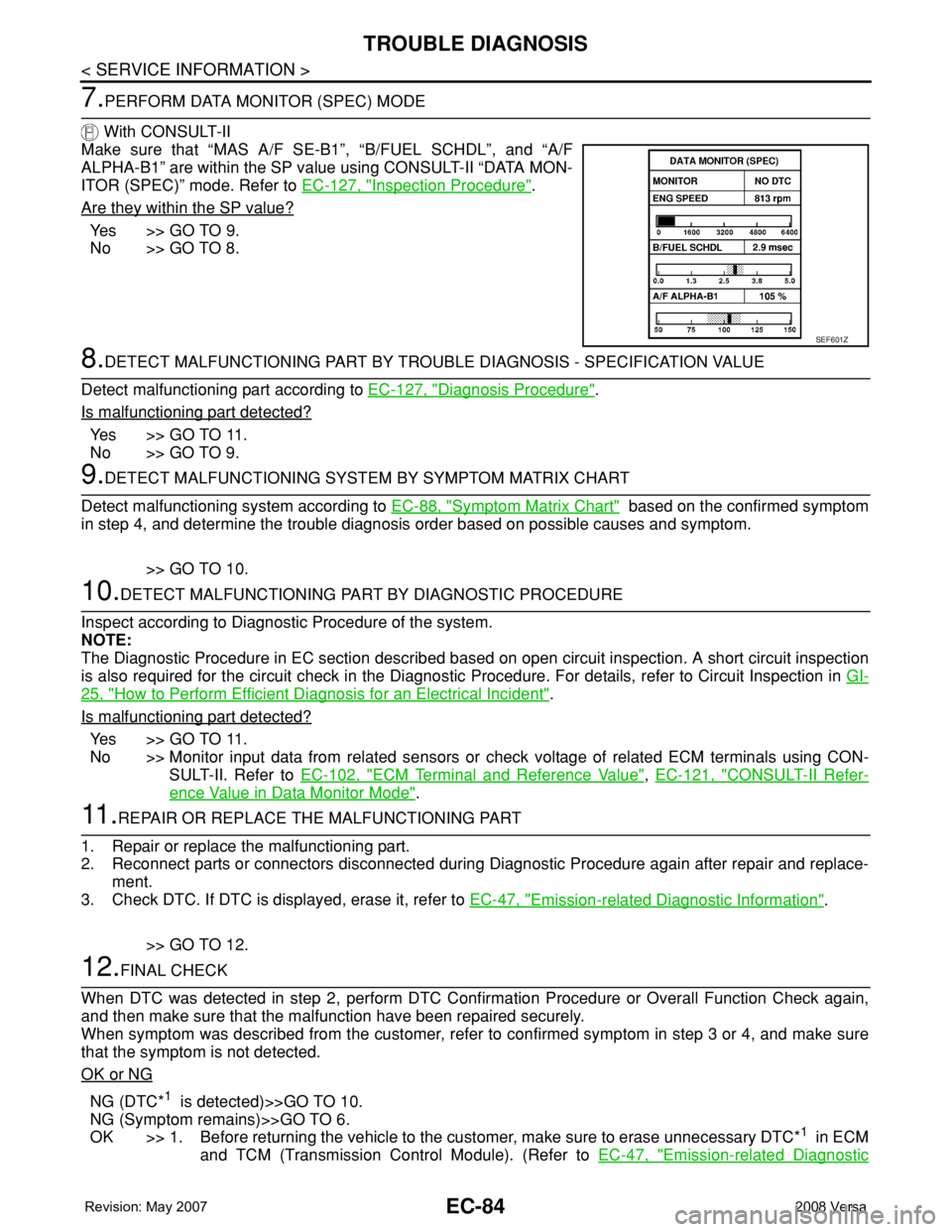
7.PERFORM DATA MONITOR (SPEC) MODE
With CONSULT-II
Make sure that “MAS A/F SE-B1”, “B/FUEL SCHDL”, and “A/F
ALPHA-B1” are within the SP value using CONSULT-II “DATA MON-
ITOR (SPEC)” mode. Refer to EC-127, "
Inspection Procedure".
Are they within the SP value?
Ye s > > G O T O 9 .
No >> GO TO 8.
8.DETECT MALFUNCTIONING PART BY TROUBLE DIAGNOSIS - SPECIFICATION VALUE
Detect malfunctioning part according to EC-127, "
Diagnosis Procedure".
Is malfunctioning part detected?
Ye s > > G O T O 11 .
No >> GO TO 9.
9.DETECT MALFUNCTIONING SYSTEM BY SYMPTOM MATRIX CHART
Detect malfunctioning system according to EC-88, "
Symptom Matrix Chart" based on the confirmed symptom
in step 4, and determine the trouble diagnosis order based on possible causes and symptom.
>> GO TO 10.
10.DETECT MALFUNCTIONING PART BY DIAGNOSTIC PROCEDURE
Inspect according to Diagnostic Procedure of the system.
NOTE:
The Diagnostic Procedure in EC section described based on open circuit inspection. A short circuit inspection
is also required for the circuit check in the Diagnostic Procedure. For details, refer to Circuit Inspection in GI-
25, "How to Perform Efficient Diagnosis for an Electrical Incident".
Is malfunctioning part detected?
Ye s > > G O T O 11 .
No >> Monitor input data from related sensors or check voltage of related ECM terminals using CON-
SULT-II. Refer to EC-102, "
ECM Terminal and Reference Value", EC-121, "CONSULT-II Refer-
ence Value in Data Monitor Mode".
11 .REPAIR OR REPLACE THE MALFUNCTIONING PART
1. Repair or replace the malfunctioning part.
2. Reconnect parts or connectors disconnected during Diagnostic Procedure again after repair and replace-
ment.
3. Check DTC. If DTC is displayed, erase it, refer to EC-47, "
Emission-related Diagnostic Information".
>> GO TO 12.
12.FINAL CHECK
When DTC was detected in step 2, perform DTC Confirmation Procedure or Overall Function Check again,
and then make sure that the malfunction have been repaired securely.
When symptom was described from the customer, refer to confirmed symptom in step 3 or 4, and make sure
that the symptom is not detected.
OK or NG
NG (DTC*1 is detected)>>GO TO 10.
NG (Symptom remains)>>GO TO 6.
OK >> 1. Before returning the vehicle to the customer, make sure to erase unnecessary DTC*
1 in ECM
and TCM (Transmission Control Module). (Refer to EC-47, "
Emission-related Diagnostic
SEF601Z
Page 1169 of 2771
TROUBLE DIAGNOSIS
EC-95
< SERVICE INFORMATION >
C
D
E
F
G
H
I
J
K
L
MA
EC
N
P O
: Vehicle front
1. Intake valve timing control solenoid
valve2. Knock sensor 3. IPDM E/R
4. Fuel pump fuse (15A) 5. Fuel level sensor unit and fuel pump
harness connector (view with in-
spection hole cover removed)6. Fuel level sensor unit and fuel pump
7. Fuel pressure regulator 8. Fuel level sensor 9. Fuel tank temperature sensor
10. Ignition coil
(with power transistor) and spark plug11. Fuel injector
BBIA0725E
Page 1170 of 2771
EC-96
< SERVICE INFORMATION >
TROUBLE DIAGNOSIS
:Vehicle front
1. Crankshaft position sensor (POS) 2. Camshaft position sensor (PHASE) 3. EVAP canister purge volume control
solenoid valve
4. EVAP service port 5. ECM harness connector 6. ECM
7. Stop lamp switch 8. Accelerator pedal position sensor
BBIA0727E
Page 1171 of 2771
TROUBLE DIAGNOSIS
EC-97
< SERVICE INFORMATION >
C
D
E
F
G
H
I
J
K
L
MA
EC
N
P O
: Vehicle front
1. Air fuel ratio (A/F) sensor 1 2. Three way catalyst (Manifold) 3. Heated oxygen sensor 2
4. Three way catalyst (Under floor) 5. Muffler 6. Air fuel ratio (A/F) sensor 1 harness
connector
7. Heated oxygen sensor 2 harness
connector
BBIA0726E
Page 1176 of 2771

EC-102
< SERVICE INFORMATION >
TROUBLE DIAGNOSIS
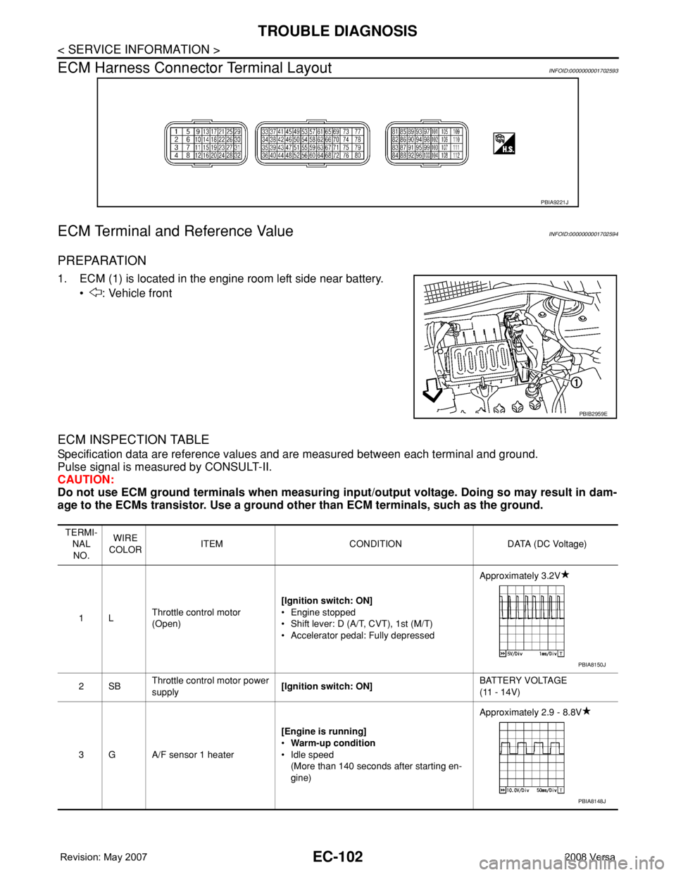
ECM Harness Connector Terminal Layout
INFOID:0000000001702593
ECM Terminal and Reference ValueINFOID:0000000001702594
PREPARATION
1. ECM (1) is located in the engine room left side near battery.
• : Vehicle front
ECM INSPECTION TABLE
Specification data are reference values and are measured between each terminal and ground.
Pulse signal is measured by CONSULT-II.
CAUTION:
Do not use ECM ground terminals when measuring input/output voltage. Doing so may result in dam-
age to the ECMs transistor. Use a ground other than ECM terminals, such as the ground.
PBIA9221J
PBIB2959E
TERMI-
NAL
NO.WIRE
COLORITEM CONDITION DATA (DC Voltage)
1LThrottle control motor
(Open)[Ignition switch: ON]
• Engine stopped
• Shift lever: D (A/T, CVT), 1st (M/T)
• Accelerator pedal: Fully depressedApproximately 3.2V
2SBThrottle control motor power
supply[Ignition switch: ON]BATTERY VOLTAGE
(11 - 14V)
3 G A/F sensor 1 heater[Engine is running]
•Warm-up condition
• Idle speed
(More than 140 seconds after starting en-
gine)Approximately 2.9 - 8.8V
PBIA8150J
PBIA8148J
Page 1181 of 2771
![NISSAN TIIDA 2008 Service Repair Manual TROUBLE DIAGNOSIS
EC-107
< SERVICE INFORMATION >
C
D
E
F
G
H
I
J
K
L
MA
EC
N
P O
65 GCamshaft position sensor
(PHASE)[Engine is running]
•Warm-up condition
• Idle speed
NOTE:
The pulse cycle chan NISSAN TIIDA 2008 Service Repair Manual TROUBLE DIAGNOSIS
EC-107
< SERVICE INFORMATION >
C
D
E
F
G
H
I
J
K
L
MA
EC
N
P O
65 GCamshaft position sensor
(PHASE)[Engine is running]
•Warm-up condition
• Idle speed
NOTE:
The pulse cycle chan](/manual-img/5/57399/w960_57399-1180.png)
TROUBLE DIAGNOSIS
EC-107
< SERVICE INFORMATION >
C
D
E
F
G
H
I
J
K
L
MA
EC
N
P O
65 GCamshaft position sensor
(PHASE)[Engine is running]
•Warm-up condition
• Idle speed
NOTE:
The pulse cycle changes depending on rpm
at idle.1.0 - 2.0V
[Engine is running]
• Engine speed: 2,000 rpm.1.0 - 2.0V
69 LPark/neutral position (PNP)
switch[Ignition switch: ON]
• Shift lever: P or N (A/T, CVT), Neutral (M/T)BATTERY VOLTAGE
(11 - 14V)
[Ignition switch: ON]
• Except aboveApproximately 0V
72 VSensor power supply
(Throttle position sensor)[Ignition switch: ON]Approximately 5V
73 PIntake valve timing control
solenoid valve[Engine is running]
•Warm-up condition
• Idle speedBATTERY VOLTAGE
(11 - 14V)
[Engine is running]
•Warm-up condition
• When revving engine up to 2,000 rpm quick-
ly7 - 10V
74 WSensor power supply
(Refrigerant pressure
sensor)[Ignition switch: ON]Approximately 5V
75 BRSensor power supply
[Crankshaft position sensor
(POS)][Ignition switch: ON]Approximately 5V
76 WEVAP control system pres-
sure sensor power supply[Ignition switch: ON]Approximately 5V
78 OSensor power supply
[Camshaft position sensor
(PHASE)][Ignition switch: ON]Approximately 5V
83 P CAN communication line — —
84 L CAN communication line — —
88 LG DATA link connector[Ignition switch: ON]
• CONSULT-II or GST: Disconnected.Approximately 10.5V
93 O Ignition switch[Ignition switch: OFF]0V
[Ignition switch: ON]BATTERY VOLTAGE
(11 - 14V) TERMI-
NAL
NO.WIRE
COLORITEM CONDITION DATA (DC Voltage)PBIB2986E
PBIB2987E
PBIA4937J
Page 1191 of 2771

TROUBLE DIAGNOSIS
EC-117
< SERVICE INFORMATION >
C
D
E
F
G
H
I
J
K
L
MA
EC
N
P O
NOTE:
Any monitored item that does not match the vehicle being diagnosed is deleted from the display automatically.
ACTIVE TEST MODE
Test Item
Monitored item [Unit]ECM
input
signalsMain
signalsDescription Remarks
ENG SPEED [rpm]×ו Indicates the engine speed computed
from the signal of the crankshaft position
sensor (POS) and camshaft position
sensor (PHASE).
MAS A/F SE-B1 [V]×ו The signal voltage of the mass air flow
sensor specification is displayed.• When engine is running specification
range is indicated.
B/FUEL SCHDL
[msec]ו “Base fuel schedule” indicates the fuel in-
jection pulse width programmed into
ECM, prior to any learned on board cor-
rection.• When engine is running specification
range is indicated.
A/F ALPHA-B1 [%]ו The mean value of the air-fuel ratio feed-
back correction factor per cycle is indi-
cated.• When engine is running specification
range is indicated.
• This data also includes the data for the
air-fuel ratio learning control.
TEST ITEM CONDITION JUDGEMENT CHECK ITEM (REMEDY)
FUEL INJEC-
TION• Engine: Return to the original
trouble condition
• Change the amount of fuel injec-
tion using CONSULT-II.If trouble symptom disappears, see
CHECK ITEM.• Harness and connectors
• Fuel injector
• Air fuel ratio (A/F) sensor 1
IGNITION TIM-
ING• Engine: Return to the original
trouble condition
• Timing light: Set
• Retard the ignition timing using
CONSULT-II.If trouble symptom disappears, see
CHECK ITEM.• Perform Idle Air Volume Learning.
POWER BAL-
ANCE• Engine: After warming up, idle the
engine.
• A/C switch OFF
• Shift lever: P or N (A/T, CVT),
Neutral (M/T)
• Cut off each fuel injector signal
one at a time using CONSULT-II.Engine runs rough or dies.• Harness and connectors
• Compression
• Fuel injector
• Power transistor
•Spark plug
• Ignition coil
COOLING FAN*• Ignition switch: ON
• Turn the cooling fan “LOW”, “HI”
and “OFF” with CONSULT-II.Cooling fan moves and stops.• Harness and connectors
• Cooling fan relay
• Cooling fan motor
ENG COOLANT
TEMP• Engine: Return to the original
trouble condition
• Change the engine coolant tem-
perature using CONSULT-II.If trouble symptom disappears, see
CHECK ITEM.• Harness and connectors
• Engine coolant temperature sen-
sor
• Fuel injector
FUEL PUMP RE-
LAY• Ignition switch: ON
(Engine stopped)
• Turn the fuel pump relay ON and
OFF using CONSULT-II and lis-
ten to operating sound.Fuel pump relay makes the operat-
ing sound.• Harness and connectors
• Fuel pump relay
PURG VOL
CONT/V• Engine: After warming up, run en-
gine at 1,500 rpm.
• Change the EVAP canister purge
volume control solenoid valve
opening percent using CON-
SULT-II.Engine speed changes according to
the opening percent.• Harness and connectors
• EVAP canister purge volume con-
trol solenoid valve