Page 1052 of 2771
WARNING LAMPS
DI-31
< SERVICE INFORMATION >
C
D
E
F
G
H
I
J
L
MA
B
DI
N
O
P
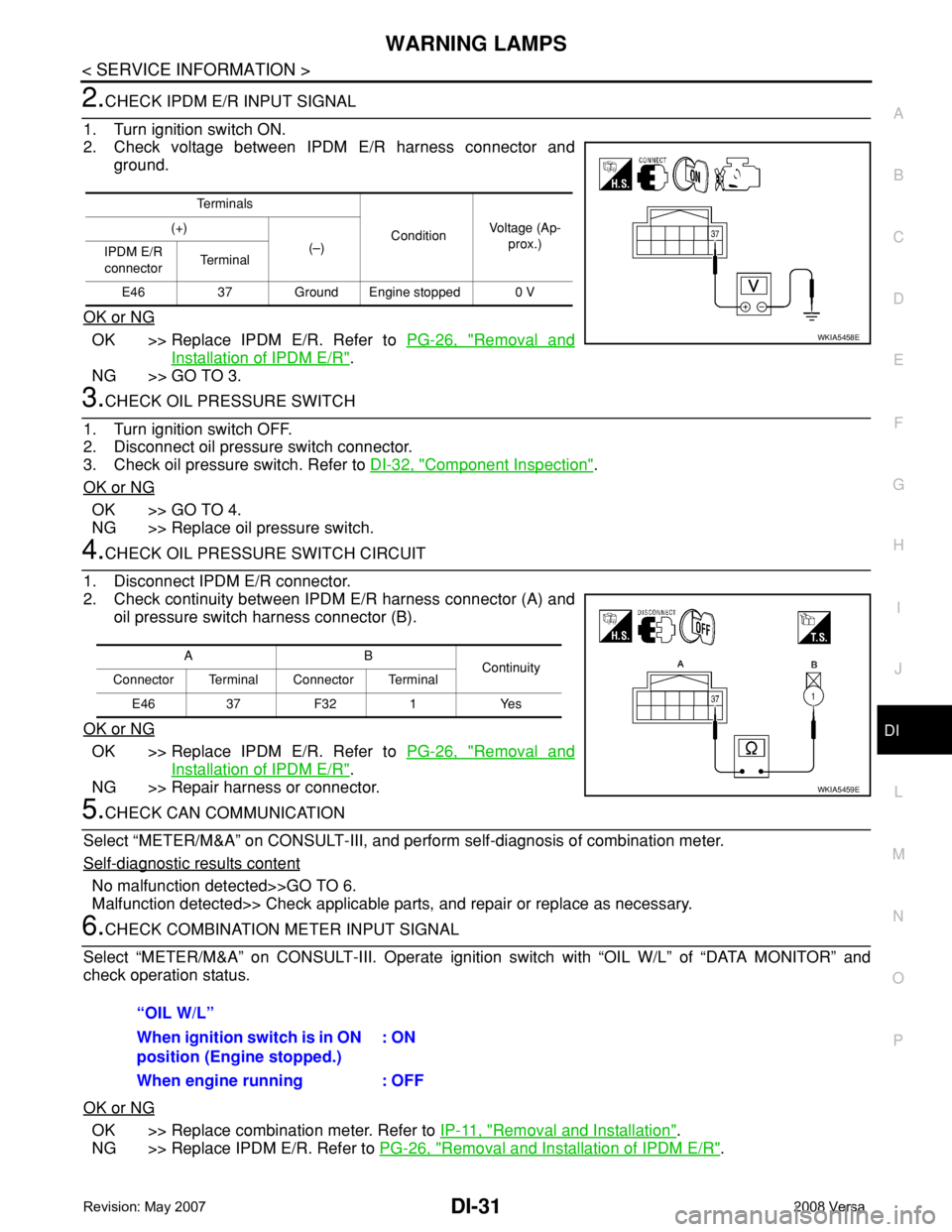
2.CHECK IPDM E/R INPUT SIGNAL
1. Turn ignition switch ON.
2. Check voltage between IPDM E/R harness connector and
ground.
OK or NG
OK >> Replace IPDM E/R. Refer to PG-26, "Removal and
Installation of IPDM E/R".
NG >> GO TO 3.
3.CHECK OIL PRESSURE SWITCH
1. Turn ignition switch OFF.
2. Disconnect oil pressure switch connector.
3. Check oil pressure switch. Refer to DI-32, "
Component Inspection".
OK or NG
OK >> GO TO 4.
NG >> Replace oil pressure switch.
4.CHECK OIL PRESSURE SWITCH CIRCUIT
1. Disconnect IPDM E/R connector.
2. Check continuity between IPDM E/R harness connector (A) and
oil pressure switch harness connector (B).
OK or NG
OK >> Replace IPDM E/R. Refer to PG-26, "Removal and
Installation of IPDM E/R".
NG >> Repair harness or connector.
5.CHECK CAN COMMUNICATION
Select “METER/M&A” on CONSULT-III, and perform self-diagnosis of combination meter.
Self
-diagnostic results content
No malfunction detected>>GO TO 6.
Malfunction detected>> Check applicable parts, and repair or replace as necessary.
6.CHECK COMBINATION METER INPUT SIGNAL
Select “METER/M&A” on CONSULT-III. Operate ignition switch with “OIL W/L” of “DATA MONITOR” and
check operation status.
OK or NG
OK >> Replace combination meter. Refer to IP-11, "Removal and Installation".
NG >> Replace IPDM E/R. Refer to PG-26, "
Removal and Installation of IPDM E/R".
Te r m i n a l s
ConditionVoltage (Ap-
prox.) (+)
(–)
IPDM E/R
connectorTe r m i n a l
E46 37 Ground Engine stopped 0 V
WKIA5458E
AB
Continuity
Connector Terminal Connector Terminal
E46 37 F32 1 Yes
WKIA5459E
“OIL W/L”
When ignition switch is in ON
position (Engine stopped.): ON
When engine running : OFF
Page 1053 of 2771
DI-32
< SERVICE INFORMATION >
WARNING LAMPS
Oil Pressure Warning Lamp Does Not Turn Off (Oil Pressure Is Normal)
INFOID:0000000001704513
NOTE:
For oil pressure inspection, refer to LU-6, "
Inspection".
1.CHECK OIL PRESSURE WARNING LAMP OPERATION
Activate IPDM E/R auto active test. Refer to PG-19, "
Auto Active Test".
Does oil pressure warning lamp blink?
YES >> GO TO 2.
NO >> GO TO 5.
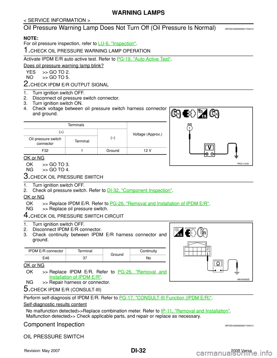
2.CHECK IPDM E/R OUTPUT SIGNAL
1. Turn ignition switch OFF.
2. Disconnect oil pressure switch connector.
3. Turn ignition switch ON.
4. Check voltage between oil pressure switch harness connector
and ground.
OK or NG
OK >> GO TO 3.
NG >> GO TO 4.
3.CHECK OIL PRESSURE SWITCH
1. Turn ignition switch OFF.
2. Check oil pressure switch. Refer to DI-32, "
Component Inspection".
OK or NG
OK >> Replace IPDM E/R. Refer to PG-26, "Removal and Installation of IPDM E/R".
NG >> Replace oil pressure switch.
4.CHECK OIL PRESSURE SWITCH CIRCUIT
1. Turn ignition switch OFF.
2. Disconnect IPDM E/R connector.
3. Check continuity between IPDM E/R harness connector and
ground.
OK or NG
OK >> Replace IPDM E/R. Refer to PG-26, "Removal and
Installation of IPDM E/R".
NG >> Repair harness or connector.
5.CHECK IPDM E/R (CONSULT-III)
Perform self-diagnosis of IPDM E/R. Refer to PG-17, "
CONSULT-III Function (IPDM E/R)".
Self
-diagnostic results content
No malfunction detected>>Replace combination meter. Refer to IP-11, "Removal and Installation".
Malfunction detected>> Check applicable parts, and repair or replace as necessary.
Component InspectionINFOID:0000000001704514
OIL PRESSURE SWITCH
Te r m i n a l s
Voltage (Approx.) (+)
(–)
Oil pressure switch
connectorTe r m i n a l
F32 1 Ground 12 V
PKIC1144E
IPDM E/R connector Terminal
GroundContinuity
E46 37 No
WKIA5460E
Page 1062 of 2771
WARNING CHIME
DI-41
< SERVICE INFORMATION >
C
D
E
F
G
H
I
J
L
MA
B
DI
N
O
P
WARNING CHIME
Component Parts and Harness Connector LocationINFOID:0000000001704521
System DescriptionINFOID:0000000001704522
• Buzzer for warning chime system is installed in the combination meter.
• The buzzer sounds when combination meter receives buzzer output signal with CAN communication line.
POWER SUPPLY AND GROUND CIRCUIT
Power is supplied at all times
• through 40A fusible link (letter g, located in the fuse and fusible link box)
• to BCM terminal 70,
1. Combination meter M24 2. BCM M18, M19, M20 (view with
glove box removed)3. Intelligent Key unit M52 (with Intelli-
gent Key)
4. Key switch and key lock solenoid
M27 (without Intelligent Key)5. Key switch and ignition knob switch
M73 (with Intelligent Key)6. Combination switch (lighting switch)
M28
7. Front door switch LH B8 8. Parking brake switch M17
AWMIA0117ZZ
Page 1069 of 2771
DI-48
< SERVICE INFORMATION >
WARNING CHIME
OK >> Check battery power supply circuit of combination meter. If OK, replace combination meter. Refer
to IP-11, "
Removal and Installation".
NG >> Replace BCM. Refer to BCS-18, "
Removal and Installation of BCM".
Front Door Switch LH Signal InspectionINFOID:0000000001704528
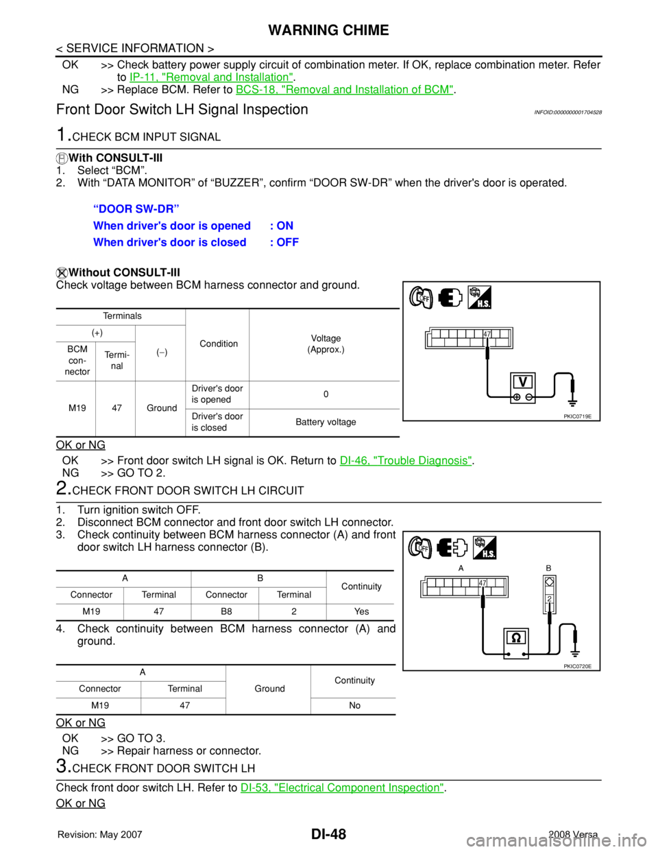
1.CHECK BCM INPUT SIGNAL
With CONSULT-III
1. Select “BCM”.
2. With “DATA MONITOR” of “BUZZER”, confirm “DOOR SW-DR” when the driver's door is operated.
Without CONSULT-III
Check voltage between BCM harness connector and ground.
OK or NG
OK >> Front door switch LH signal is OK. Return to DI-46, "Trouble Diagnosis".
NG >> GO TO 2.
2.CHECK FRONT DOOR SWITCH LH CIRCUIT
1. Turn ignition switch OFF.
2. Disconnect BCM connector and front door switch LH connector.
3. Check continuity between BCM harness connector (A) and front
door switch LH harness connector (B).
4. Check continuity between BCM harness connector (A) and
ground.
OK or NG
OK >> GO TO 3.
NG >> Repair harness or connector.
3.CHECK FRONT DOOR SWITCH LH
Check front door switch LH. Refer to DI-53, "
Electrical Component Inspection".
OK or NG
“DOOR SW-DR”
When driver's door is opened : ON
When driver's door is closed : OFF
Te r m i n a l s
ConditionVol tag e
(Approx.) (+)
(−) BCM
con-
nectorTe r m i -
nal
M19 47 GroundDriver's door
is opened0
Driver's door
is closedBattery voltage
PKIC0719E
AB
Continuity
Connector Terminal Connector Terminal
M19 47 B8 2 Yes
A
GroundContinuity
Connector Terminal
M19 47 No
PKIC0720E
Page 1070 of 2771
WARNING CHIME
DI-49
< SERVICE INFORMATION >
C
D
E
F
G
H
I
J
L
MA
B
DI
N
O
P
OK >> Replace BCM. Refer to BCS-18, "Removal and Installation of BCM".
NG >> Replace front door switch LH.
Key Switch Signal Inspection (Without Intelligent Key)INFOID:0000000001704529
1.CHECK FUSE
Check if the key switch and key lock solenoid 10A fuse [No. 14, located in the fuse block (J/B)] is blown.
OK or NG
OK >> GO TO 2.
NG >> Be sure to repair the cause of malfunction before installing new fuse. Refer to PG-3
.
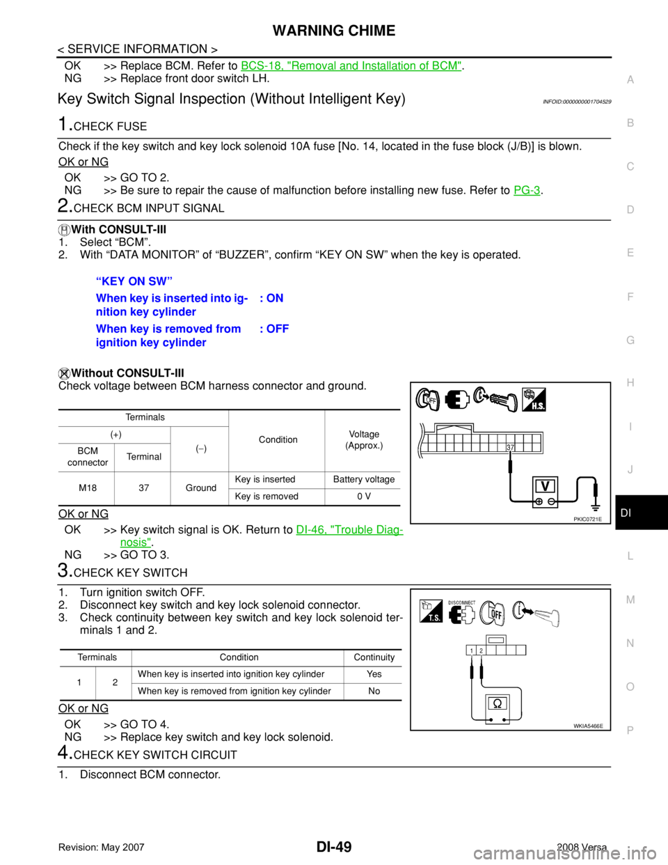
2.CHECK BCM INPUT SIGNAL
With CONSULT-III
1. Select “BCM”.
2. With “DATA MONITOR” of “BUZZER”, confirm “KEY ON SW” when the key is operated.
Without CONSULT-III
Check voltage between BCM harness connector and ground.
OK or NG
OK >> Key switch signal is OK. Return to DI-46, "Trouble Diag-
nosis".
NG >> GO TO 3.
3.CHECK KEY SWITCH
1. Turn ignition switch OFF.
2. Disconnect key switch and key lock solenoid connector.
3. Check continuity between key switch and key lock solenoid ter-
minals 1 and 2.
OK or NG
OK >> GO TO 4.
NG >> Replace key switch and key lock solenoid.
4.CHECK KEY SWITCH CIRCUIT
1. Disconnect BCM connector.“KEY ON SW”
When key is inserted into ig-
nition key cylinder: ON
When key is removed from
ignition key cylinder: OFF
Te r m i n a l s
ConditionVoltag e
(Approx.) (+)
(−)
BCM
connectorTe r m i n a l
M18 37 GroundKey is inserted Battery voltage
Key is removed 0 V
PKIC0721E
Terminals Condition Continuity
12When key is inserted into ignition key cylinder Yes
When key is removed from ignition key cylinder No
WKIA5466E
Page 1071 of 2771
DI-50
< SERVICE INFORMATION >
WARNING CHIME
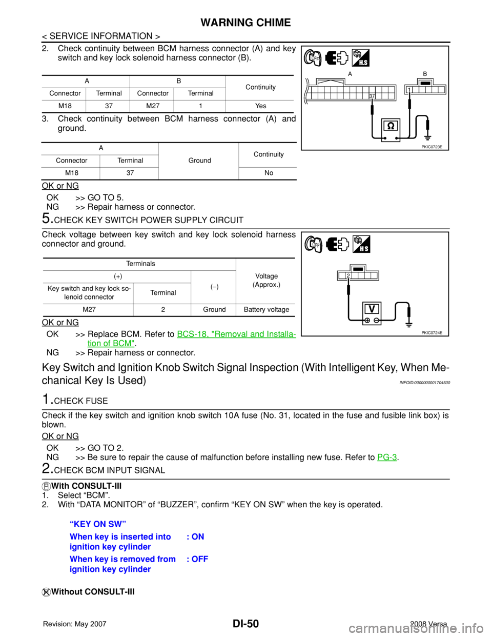
2. Check continuity between BCM harness connector (A) and key
switch and key lock solenoid harness connector (B).
3. Check continuity between BCM harness connector (A) and
ground.
OK or NG
OK >> GO TO 5.
NG >> Repair harness or connector.
5.CHECK KEY SWITCH POWER SUPPLY CIRCUIT
Check voltage between key switch and key lock solenoid harness
connector and ground.
OK or NG
OK >> Replace BCM. Refer to BCS-18, "Removal and Installa-
tion of BCM".
NG >> Repair harness or connector.
Key Switch and Ignition Knob Switch Signal Inspection (With Intelligent Key, When Me-
chanical Key Is Used)
INFOID:0000000001704530
1.CHECK FUSE
Check if the key switch and ignition knob switch 10A fuse (No. 31, located in the fuse and fusible link box) is
blown.
OK or NG
OK >> GO TO 2.
NG >> Be sure to repair the cause of malfunction before installing new fuse. Refer to PG-3
.
2.CHECK BCM INPUT SIGNAL
With CONSULT-III
1. Select “BCM”.
2. With “DATA MONITOR” of “BUZZER”, confirm “KEY ON SW” when the key is operated.
Without CONSULT-III
AB
Continuity
Connector Terminal Connector Terminal
M18 37 M27 1 Yes
A
GroundContinuity
Connector Terminal
M18 37 No
PKIC0723E
Te r m i n a l s
Voltage
(Approx.) (+)
(−)
Key switch and key lock so-
lenoid connectorTe r m i n a l
M27 2 Ground Battery voltage
PKIC0724E
“KEY ON SW”
When key is inserted into
ignition key cylinder: ON
When key is removed from
ignition key cylinder: OFF
Page 1072 of 2771
WARNING CHIME
DI-51
< SERVICE INFORMATION >
C
D
E
F
G
H
I
J
L
MA
B
DI
N
O
P
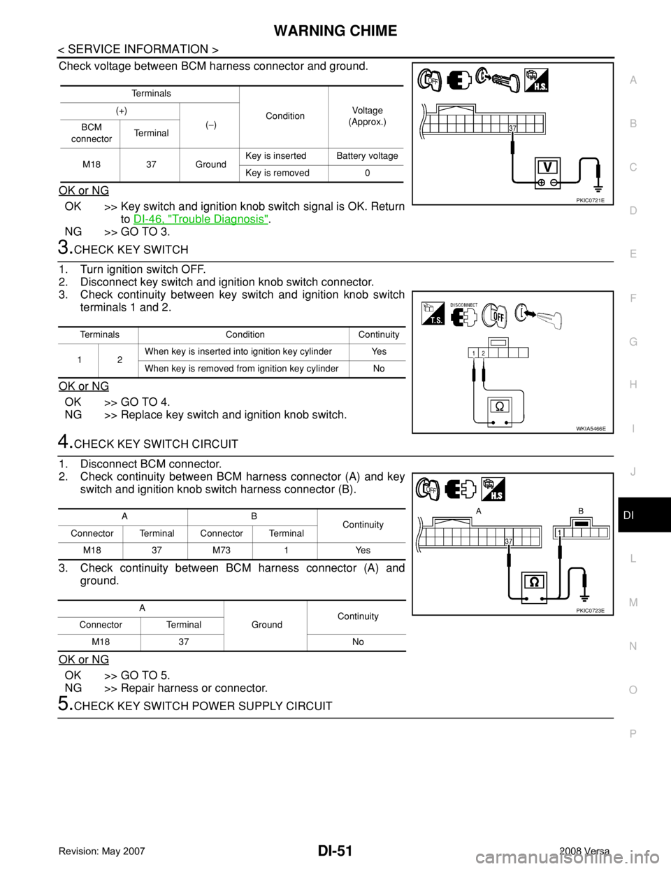
Check voltage between BCM harness connector and ground.
OK or NG
OK >> Key switch and ignition knob switch signal is OK. Return
to DI-46, "
Trouble Diagnosis".
NG >> GO TO 3.
3.CHECK KEY SWITCH
1. Turn ignition switch OFF.
2. Disconnect key switch and ignition knob switch connector.
3. Check continuity between key switch and ignition knob switch
terminals 1 and 2.
OK or NG
OK >> GO TO 4.
NG >> Replace key switch and ignition knob switch.
4.CHECK KEY SWITCH CIRCUIT
1. Disconnect BCM connector.
2. Check continuity between BCM harness connector (A) and key
switch and ignition knob switch harness connector (B).
3. Check continuity between BCM harness connector (A) and
ground.
OK or NG
OK >> GO TO 5.
NG >> Repair harness or connector.
5.CHECK KEY SWITCH POWER SUPPLY CIRCUIT
Te r m i n a l s
ConditionVol tag e
(Approx.) (+)
(−)
BCM
connectorTe r m i n a l
M18 37 GroundKey is inserted Battery voltage
Key is removed 0
PKIC0721E
Terminals Condition Continuity
12When key is inserted into ignition key cylinder Yes
When key is removed from ignition key cylinder No
WKIA5466E
AB
Continuity
Connector Terminal Connector Terminal
M1837M73 1 Yes
A
GroundContinuity
Connector Terminal
M18 37 No
PKIC0723E
Page 1073 of 2771
DI-52
< SERVICE INFORMATION >
WARNING CHIME
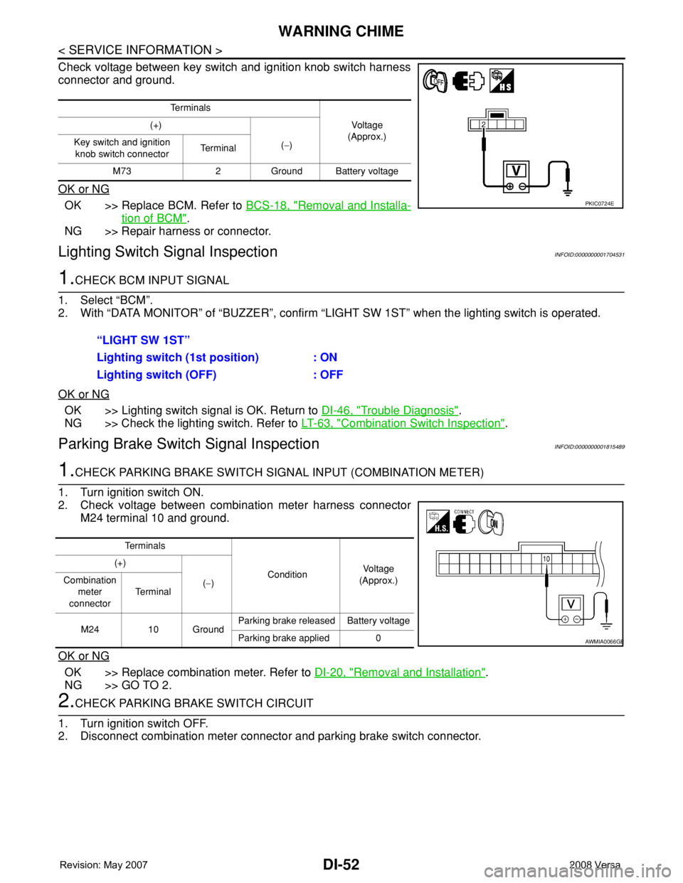
Check voltage between key switch and ignition knob switch harness
connector and ground.
OK or NG
OK >> Replace BCM. Refer to BCS-18, "Removal and Installa-
tion of BCM".
NG >> Repair harness or connector.
Lighting Switch Signal InspectionINFOID:0000000001704531
1.CHECK BCM INPUT SIGNAL
1. Select “BCM”.
2. With “DATA MONITOR” of “BUZZER”, confirm “LIGHT SW 1ST” when the lighting switch is operated.
OK or NG
OK >> Lighting switch signal is OK. Return to DI-46, "Trouble Diagnosis".
NG >> Check the lighting switch. Refer to LT-63, "
Combination Switch Inspection".
Parking Brake Switch Signal InspectionINFOID:0000000001815489
1.CHECK PARKING BRAKE SWITCH SIGNAL INPUT (COMBINATION METER)
1. Turn ignition switch ON.
2. Check voltage between combination meter harness connector
M24 terminal 10 and ground.
OK or NG
OK >> Replace combination meter. Refer to DI-20, "Removal and Installation".
NG >> GO TO 2.
2.CHECK PARKING BRAKE SWITCH CIRCUIT
1. Turn ignition switch OFF.
2. Disconnect combination meter connector and parking brake switch connector.
Te r m i n a l s
Vo l ta g e
(Approx.) (+)
(−) Key switch and ignition
knob switch connector Te r m i n a l
M73 2 Ground Battery voltage
PKIC0724E
“LIGHT SW 1ST”
Lighting switch (1st position) : ON
Lighting switch (OFF) : OFF
Te r m i n a l s
ConditionVoltag e
(Approx.) (+)
(−) Combination
meter
connectorTe r m i n a l
M24 10 GroundParking brake released Battery voltage
Parking brake applied 0
AWMIA0066GB