2008 NISSAN TIIDA oil type
[x] Cancel search: oil typePage 2348 of 2771
MTC-10
< SERVICE INFORMATION >
PREPARATION
PREPARATION
Special Service ToolINFOID:0000000001704283
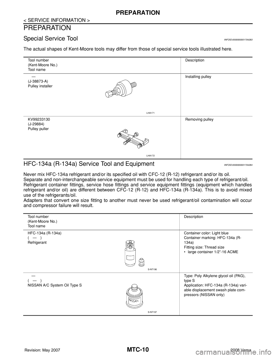
The actual shapes of Kent-Moore tools may differ from those of special service tools illustrated here.
HFC-134a (R-134a) Service Tool and EquipmentINFOID:0000000001704284
Never mix HFC-134a refrigerant and/or its specified oil with CFC-12 (R-12) refrigerant and/or its oil.
Separate and non-interchangeable service equipment must be used for handling each type of refrigerant/oil.
Refrigerant container fittings, service hose fittings and service equipment fittings (equipment which handles
refrigerant and/or oil) are different between CFC-12 (R-12) and HFC-134a (R-134a). This is to avoid mixed
use of the refrigerants/oil.
Adapters that convert one size fitting to another must never be used refrigerant/oil contamination will occur
and compressor failure will result.
Tool number
(Kent-Moore No.)
Tool nameDescription
—
(J-38873-A)
Pulley installerInstalling pulley
KV99233130
(J-29884)
Pulley pullerRemoving pulley
LHA171
LHA172
Tool number
(Kent-Moore No.)
Tool nameDescription
HFC-134a (R-134a)
(—)
RefrigerantContainer color: Light blue
Container marking: HFC-134a (R-
134a)
Fitting size: Thread size
• large container 1/2”-16 ACME
—
(—)
NISSAN A/C System Oil Type SType: Poly Alkylene glycol oil (PAG),
type S
Application: HFC-134a (R-134a) vari-
able displacement swash plate com-
pressors (NISSAN only)
S-NT196
S-NT197
Page 2349 of 2771
PREPARATION
MTC-11
< SERVICE INFORMATION >
C
D
E
F
G
H
I
K
L
MA
B
MTC
N
O
P
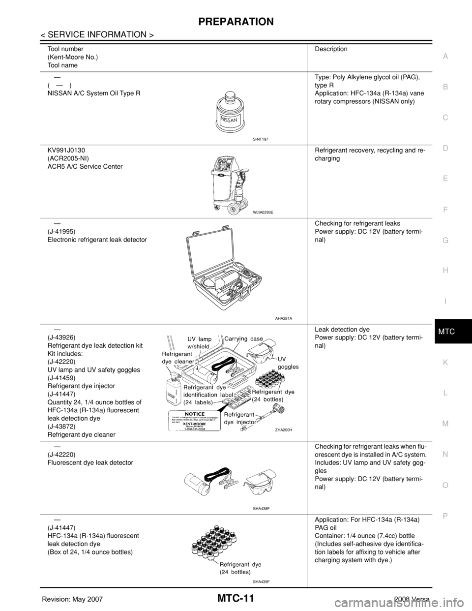
—
(—)
NISSAN A/C System Oil Type RType: Poly Alkylene glycol oil (PAG),
type R
Application: HFC-134a (R-134a) vane
rotary compressors (NISSAN only)
KV991J0130
(ACR2005-NI)
ACR5 A/C Service CenterRefrigerant recovery, recycling and re-
charging
—
(J-41995)
Electronic refrigerant leak detectorChecking for refrigerant leaks
Power supply: DC 12V (battery termi-
nal)
—
(J-43926)
Refrigerant dye leak detection kit
Kit includes:
(J-42220)
UV lamp and UV safety goggles
(J-41459)
Refrigerant dye injector
(J-41447)
Quantity 24, 1/4 ounce bottles of
HFC-134a (R-134a) fluorescent
leak detection dye
(J-43872)
Refrigerant dye cleanerLeak detection dye
Power supply: DC 12V (battery termi-
nal)
—
(J-42220)
Fluorescent dye leak detectorChecking for refrigerant leaks when flu-
orescent dye is installed in A/C system.
Includes: UV lamp and UV safety gog-
gles
Power supply: DC 12V (battery termi-
nal)
—
(J-41447)
HFC-134a (R-134a) fluorescent
leak detection dye
(Box of 24, 1/4 ounce bottles)Application: For HFC-134a (R-134a)
PA G o i l
Container: 1/4 ounce (7.4cc) bottle
(Includes self-adhesive dye identifica-
tion labels for affixing to vehicle after
charging system with dye.) Tool number
(Kent-Moore No.)
Tool nameDescription
S-NT197
WJIA0293E
AHA281A
ZHA200H
SHA438F
SHA439F
Page 2354 of 2771
MTC-16
< SERVICE INFORMATION >
OIL
OIL
Maintenance of Oil Quantity in CompressorINFOID:0000000001704289
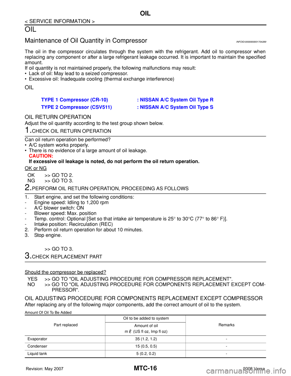
The oil in the compressor circulates through the system with the refrigerant. Add oil to compressor when
replacing any component or after a large refrigerant leakage occurred. It is important to maintain the specified
amount.
If oil quantity is not maintained properly, the following malfunctions may result:
• Lack of oil: May lead to a seized compressor.
• Excessive oil: Inadequate cooling (thermal exchange interference)
OIL
OIL RETURN OPERATION
Adjust the oil quantity according to the test group shown below.
1.CHECK OIL RETURN OPERATION
Can oil return operation be performed?
• A/C system works properly.
• There is no evidence of a large amount of oil leakage.
CAUTION:
If excessive oil leakage is noted, do not perform the oil return operation.
OK or NG
OK >> GO TO 2.
NG >> GO TO 3.
2.PERFORM OIL RETURN OPERATION, PROCEEDING AS FOLLOWS
1. Start engine, and set the following conditions:
- Engine speed: Idling to 1,200 rpm
- A/C blower switch: ON
- Blower speed: Max. position
- Temp. control: Optional [Set so that intake air temperature is 25° to 30°C (77° to 86° F)].
- Intake position: Recirculation (REC)
2. Perform oil return operation for about 10 minutes.
3. Stop engine.
>> GO TO 3.
3.CHECK REPLACEMENT PART
Should the compressor be replaced?
YES >> GO TO "OIL ADJUSTING PROCEDURE FOR COMPRESSOR REPLACEMENT".
NO >> GO TO "OIL ADJUSTING PROCEDURE FOR COMPONENTS REPLACEMENT EXCEPT COM-
PRESSOR".
OIL ADJUSTING PROCEDURE FOR COMPONENTS REPLACEMENT EXCEPT COMPRESSOR
After replacing any of the following major components, add the correct amount of oil to the system.
Amount Of Oil To Be Added
TYPE 1 Compressor (CR-10) : NISSAN A/C System Oil Type R
TYPE 2 Compressor (CSV511) : NISSAN A/C System Oil Type S
Part replacedOil to be added to system
Remarks
Amount of oil
m (US fl oz, Imp fl oz)
Evaporator 35 (1.2, 1.2) -
Condenser 15 (0.5, 0.5) -
Liquid tank 5 (0.2, 0.2) -
Page 2395 of 2771
THERMO CONTROL AMPLIFIER
MTC-57
< SERVICE INFORMATION >
C
D
E
F
G
H
I
K
L
MA
B
MTC
N
O
P
THERMO CONTROL AMPLIFIER
Removal and InstallationINFOID:0000000001704311
NOTE:
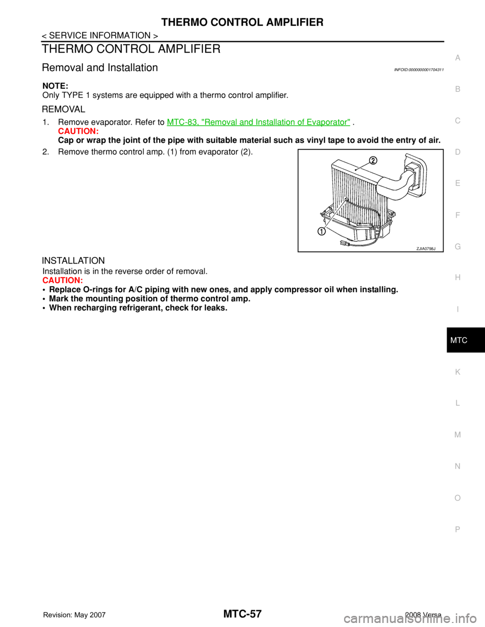
Only TYPE 1 systems are equipped with a thermo control amplifier.
REMOVAL
1. Remove evaporator. Refer to MTC-83, "Removal and Installation of Evaporator" .
CAUTION:
Cap or wrap the joint of the pipe with suitable material such as vinyl tape to avoid the entry of air.
2. Remove thermo control amp. (1) from evaporator (2).
INSTALLATION
Installation is in the reverse order of removal.
CAUTION:
• Replace O-rings for A/C piping with new ones, and apply compressor oil when installing.
• Mark the mounting position of thermo control amp.
• When recharging refrigerant, check for leaks.
ZJIA0798J
Page 2397 of 2771
A/C UNIT ASSEMBLY
MTC-59
< SERVICE INFORMATION >
C
D
E
F
G
H
I
K
L
MA
B
MTC
N
O
P
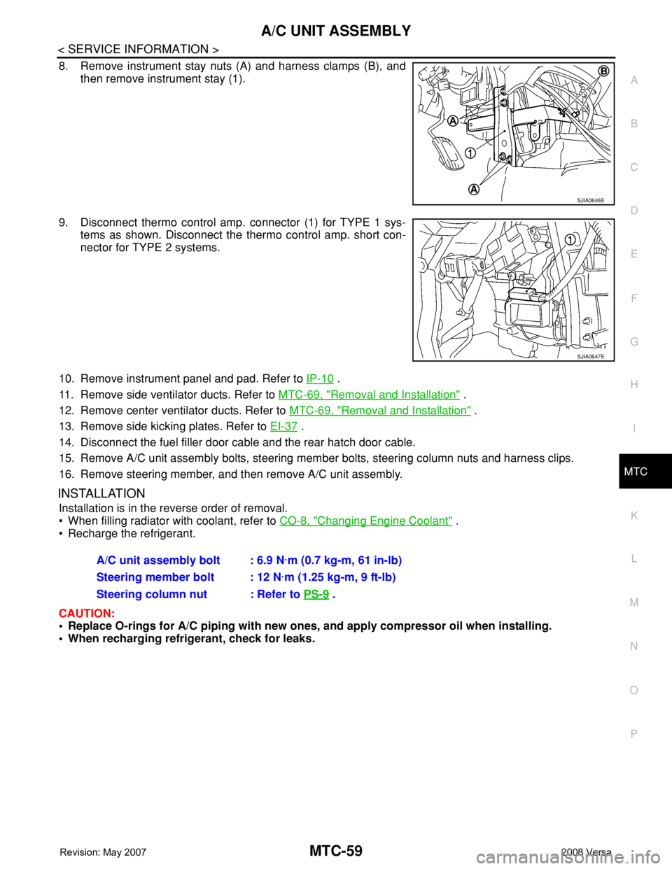
8. Remove instrument stay nuts (A) and harness clamps (B), and
then remove instrument stay (1).
9. Disconnect thermo control amp. connector (1) for TYPE 1 sys-
tems as shown. Disconnect the thermo control amp. short con-
nector for TYPE 2 systems.
10. Remove instrument panel and pad. Refer to IP-10
.
11. Remove side ventilator ducts. Refer to MTC-69, "
Removal and Installation" .
12. Remove center ventilator ducts. Refer to MTC-69, "
Removal and Installation" .
13. Remove side kicking plates. Refer to EI-37
.
14. Disconnect the fuel filler door cable and the rear hatch door cable.
15. Remove A/C unit assembly bolts, steering member bolts, steering column nuts and harness clips.
16. Remove steering member, and then remove A/C unit assembly.
INSTALLATION
Installation is in the reverse order of removal.
• When filling radiator with coolant, refer to CO-8, "
Changing Engine Coolant" .
• Recharge the refrigerant.
CAUTION:
• Replace O-rings for A/C piping with new ones, and apply compressor oil when installing.
• When recharging refrigerant, check for leaks.
SJIA0646E
SJIA0647E
A/C unit assembly bolt : 6.9 N·m (0.7 kg-m, 61 in-lb)
Steering member bolt : 12 N·m (1.25 kg-m, 9 ft-lb)
Steering column nut : Refer to PS-9
.
Page 2417 of 2771
REFRIGERANT LINES
MTC-79
< SERVICE INFORMATION >
C
D
E
F
G
H
I
K
L
MA
B
MTC
N
O
P
INSPECTION FOR CLUTCH DISC TO PULLEY CLEARANCE
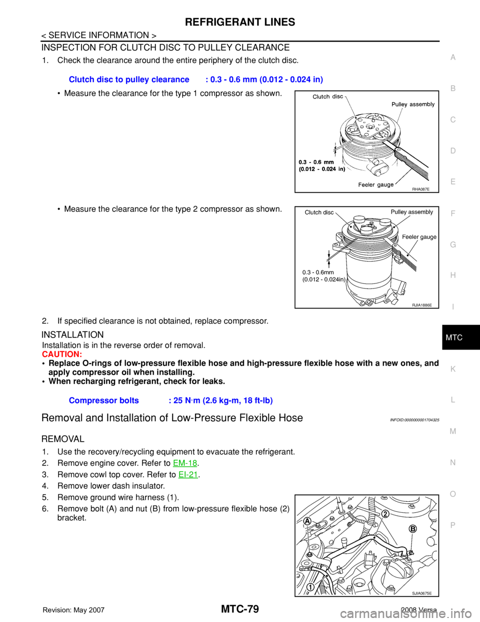
1. Check the clearance around the entire periphery of the clutch disc.
• Measure the clearance for the type 1 compressor as shown.
• Measure the clearance for the type 2 compressor as shown.
2. If specified clearance is not obtained, replace compressor.
INSTALLATION
Installation is in the reverse order of removal.
CAUTION:
• Replace O-rings of low-pressure flexible hose and high-pressure flexible hose with a new ones, and
apply compressor oil when installing.
• When recharging refrigerant, check for leaks.
Removal and Installation of Low-Pressure Flexible HoseINFOID:0000000001704325
REMOVAL
1. Use the recovery/recycling equipment to evacuate the refrigerant.
2. Remove engine cover. Refer to EM-18
.
3. Remove cowl top cover. Refer to EI-21
.
4. Remove lower dash insulator.
5. Remove ground wire harness (1).
6. Remove bolt (A) and nut (B) from low-pressure flexible hose (2)
bracket.Clutch disc to pulley clearance : 0.3 - 0.6 mm (0.012 - 0.024 in)
RHA087E
RJIA1886E
Compressor bolts : 25 N·m (2.6 kg-m, 18 ft-lb)
SJIA0675E
Page 2422 of 2771
MTC-84
< SERVICE INFORMATION >
REFRIGERANT LINES
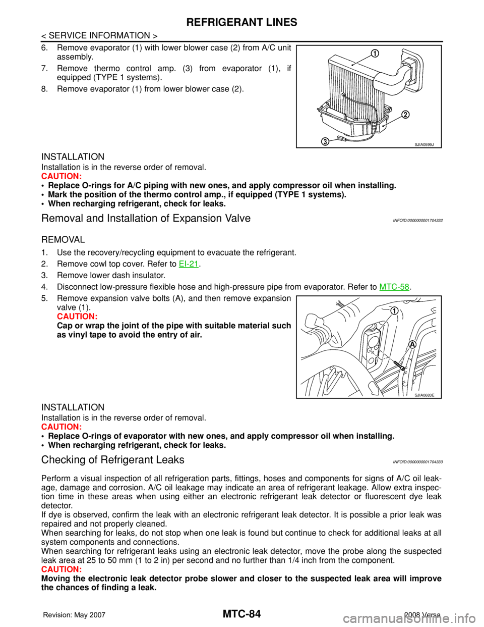
6. Remove evaporator (1) with lower blower case (2) from A/C unit
assembly.
7. Remove thermo control amp. (3) from evaporator (1), if
equipped (TYPE 1 systems).
8. Remove evaporator (1) from lower blower case (2).
INSTALLATION
Installation is in the reverse order of removal.
CAUTION:
• Replace O-rings for A/C piping with new ones, and apply compressor oil when installing.
• Mark the position of the thermo control amp., if equipped (TYPE 1 systems).
• When recharging refrigerant, check for leaks.
Removal and Installation of Expansion ValveINFOID:0000000001704332
REMOVAL
1. Use the recovery/recycling equipment to evacuate the refrigerant.
2. Remove cowl top cover. Refer to EI-21
.
3. Remove lower dash insulator.
4. Disconnect low-pressure flexible hose and high-pressure pipe from evaporator. Refer to MTC-58
.
5. Remove expansion valve bolts (A), and then remove expansion
valve (1).
CAUTION:
Cap or wrap the joint of the pipe with suitable material such
as vinyl tape to avoid the entry of air.
INSTALLATION
Installation is in the reverse order of removal.
CAUTION:
• Replace O-rings of evaporator with new ones, and apply compressor oil when installing.
• When recharging refrigerant, check for leaks.
Checking of Refrigerant LeaksINFOID:0000000001704333
Perform a visual inspection of all refrigeration parts, fittings, hoses and components for signs of A/C oil leak-
age, damage and corrosion. A/C oil leakage may indicate an area of refrigerant leakage. Allow extra inspec-
tion time in these areas when using either an electronic refrigerant leak detector or fluorescent dye leak
detector.
If dye is observed, confirm the leak with an electronic refrigerant leak detector. It is possible a prior leak was
repaired and not properly cleaned.
When searching for leaks, do not stop when one leak is found but continue to check for additional leaks at all
system components and connections.
When searching for refrigerant leaks using an electronic leak detector, move the probe along the suspected
leak area at 25 to 50 mm (1 to 2 in) per second and no further than 1/4 inch from the component.
CAUTION:
Moving the electronic leak detector probe slower and closer to the suspected leak area will improve
the chances of finding a leak.
SJIA0599J
SJIA0683E
Page 2426 of 2771
MTC-88
< SERVICE INFORMATION >
SERVICE DATA AND SPECIFICATIONS (SDS)
SERVICE DATA AND SPECIFICATIONS (SDS)
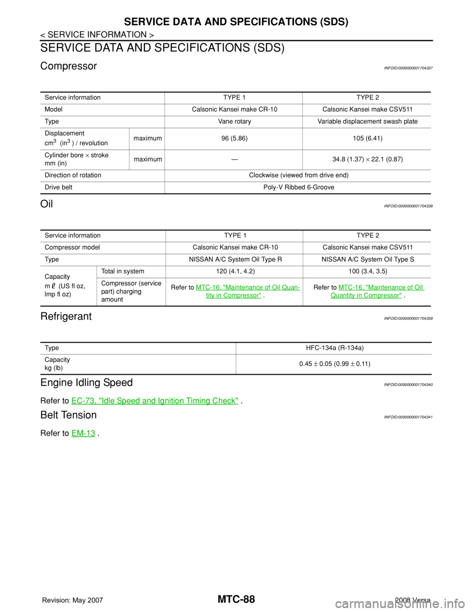
CompressorINFOID:0000000001704337
OilINFOID:0000000001704338
RefrigerantINFOID:0000000001704339
Engine Idling SpeedINFOID:0000000001704340
Refer to EC-73, "Idle Speed and Ignition Timing Check" .
Belt TensionINFOID:0000000001704341
Refer to EM-13 .
Service information TYPE 1 TYPE 2
Model Calsonic Kansei make CR-10 Calsonic Kansei make CSV511
Type Vane rotary Variable displacement swash plate
Displacement
cm
3 (in3 ) / revolutionmaximum 96 (5.86) 105 (6.41)
Cylinder bore × stroke
mm (in)maximum — 34.8 (1.37) × 22.1 (0.87)
Direction of rotation Clockwise (viewed from drive end)
Drive belt Poly-V Ribbed 6-Groove
Service information TYPE 1 TYPE 2
Compressor model Calsonic Kansei make CR-10 Calsonic Kansei make CSV511
Type NISSAN A/C System Oil Type R NISSAN A/C System Oil Type S
Capacity
m (US fl oz,
lmp fl oz)Total in system 120 (4.1, 4.2) 100 (3.4, 3.5)
Compressor (service
part) charging
amountRefer to MTC-16, "
Maintenance of Oil Quan-
tity in Compressor" .Refer to MTC-16, "
Maintenance of Oil
Quantity in Compressor" .
Ty p eHFC-134a (R-134a)
Capacity
kg (lb)0.45 ± 0.05 (0.99 ± 0.11)