2008 NISSAN TIIDA oil type
[x] Cancel search: oil typePage 1386 of 2771
EC-312
< SERVICE INFORMATION >
DTC P0420 THREE WAY CATALYST FUNCTION
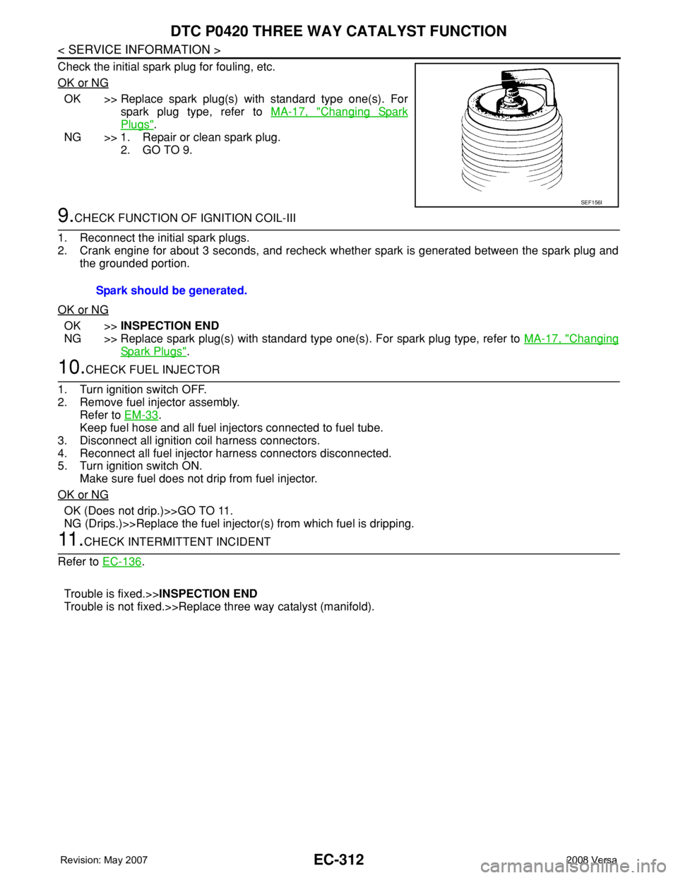
Check the initial spark plug for fouling, etc.
OK or NG
OK >> Replace spark plug(s) with standard type one(s). For
spark plug type, refer to MA-17, "
Changing Spark
Plugs".
NG >> 1. Repair or clean spark plug.
2. GO TO 9.
9.CHECK FUNCTION OF IGNITION COIL-III
1. Reconnect the initial spark plugs.
2. Crank engine for about 3 seconds, and recheck whether spark is generated between the spark plug and
the grounded portion.
OK or NG
OK >>INSPECTION END
NG >> Replace spark plug(s) with standard type one(s). For spark plug type, refer to MA-17, "
Changing
Spark Plugs".
10.CHECK FUEL INJECTOR
1. Turn ignition switch OFF.
2. Remove fuel injector assembly.
Refer to EM-33
.
Keep fuel hose and all fuel injectors connected to fuel tube.
3. Disconnect all ignition coil harness connectors.
4. Reconnect all fuel injector harness connectors disconnected.
5. Turn ignition switch ON.
Make sure fuel does not drip from fuel injector.
OK or NG
OK (Does not drip.)>>GO TO 11.
NG (Drips.)>>Replace the fuel injector(s) from which fuel is dripping.
11 .CHECK INTERMITTENT INCIDENT
Refer to EC-136
.
Trouble is fixed.>>INSPECTION END
Trouble is not fixed.>>Replace three way catalyst (manifold).
SEF156I
Spark should be generated.
Page 1626 of 2771
PRECAUTIONS
EI-3
< PRECAUTION >
C
D
E
F
G
H
J
K
L
MA
B
EI
N
O
P
PRECAUTION
PRECAUTIONS
Precaution for Supplemental Restraint System (SRS) "AIR BAG" and "SEAT BELT
PRE-TENSIONER"
INFOID:0000000001704210
The Supplemental Restraint System such as “AIR BAG” and “SEAT BELT PRE-TENSIONER”, used along
with a front seat belt, helps to reduce the risk or severity of injury to the driver and front passenger for certain
types of collision. This system includes seat belt switch inputs and dual stage front air bag modules. The SRS
system uses the seat belt switches to determine the front air bag deployment, and may only deploy one front
air bag, depending on the severity of a collision and whether the front occupants are belted or unbelted.
Information necessary to service the system safely is included in the SR and SB section of this Service Man-
ual.
WARNING:
• To avoid rendering the SRS inoperative, which could increase the risk of personal injury or death in
the event of a collision which would result in air bag inflation, all maintenance must be performed by
an authorized NISSAN/INFINITI dealer.
• Improper maintenance, including incorrect removal and installation of the SRS, can lead to personal
injury caused by unintentional activation of the system. For removal of Spiral Cable and Air Bag
Module, see the SR section.
• Do not use electrical test equipment on any circuit related to the SRS unless instructed to in this
Service Manual. SRS wiring harnesses can be identified by yellow and/or orange harnesses or har-
ness connectors.
PrecautionINFOID:0000000001704211
• When removing or disassembling any part, be careful not to damage or deform it. Protect parts which may
get in the way with cloth.
• When removing parts with a screwdriver or other tool, protect parts by wrapping them with vinyl or tape.
• Keep removed parts protected with cloth.
• If a clip is deformed or damaged, replace it.
• If an unreusable part is removed, replace it with a new one.
• Tighten bolts and nuts firmly to the specified torque.
• After re-assembly has been completed, make sure each part functions correctly.
• Remove stains in the following way.
- Water-soluble stains:
Dip a cloth in warm water, and squeeze tightly. After wiping the stain, wipe with a soft dry cloth.
- Oil stain:
Dissolve a synthetic detergent in warm water (density of 2 to 3% or less), dip the cloth, then clean off the
stain with the cloth. Next, dip the soft cloth in fresh water, and then squeeze it tightly. Then clean off the
detergent completely. Then wipe the area with a soft dry cloth.
• Do not use any organic solvent, such as thinner or benzine.
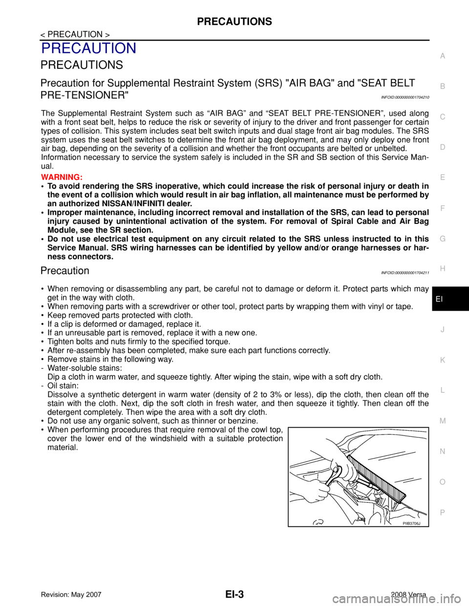
• When performing procedures that require removal of the cowl top,
cover the lower end of the windshield with a suitable protection
material.
PIIB3706J
Page 1689 of 2771
EM-12
< SERVICE INFORMATION >
NOISE, VIBRATION AND HARSHNESS (NVH) TROUBLESHOOTING
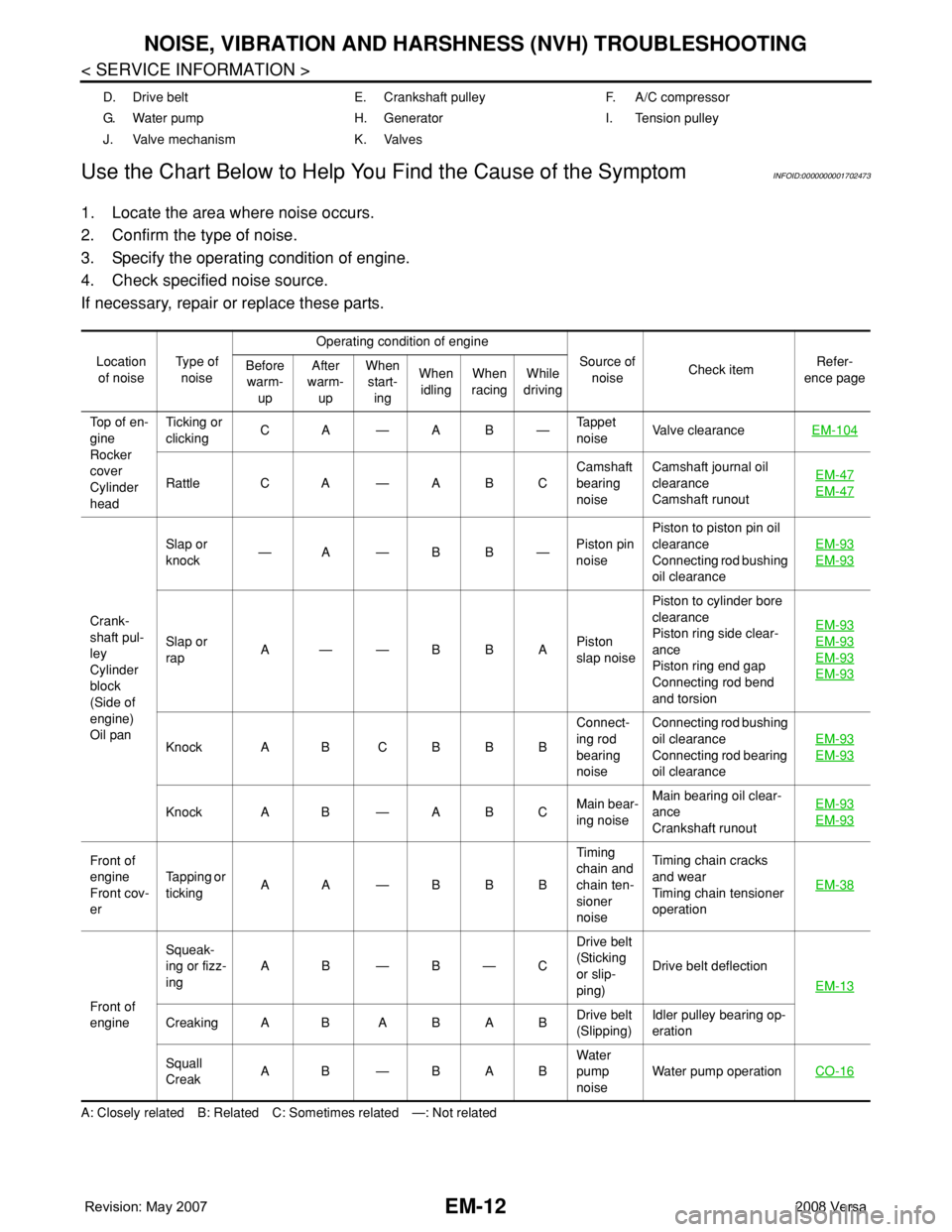
Use the Chart Below to Help You Find the Cause of the Symptom
INFOID:0000000001702473
1. Locate the area where noise occurs.
2. Confirm the type of noise.
3. Specify the operating condition of engine.
4. Check specified noise source.
If necessary, repair or replace these parts.
A: Closely related B: Related C: Sometimes related —: Not relatedD. Drive belt E. Crankshaft pulley F. A/C compressor
G. Water pump H. Generator I. Tension pulley
J. Valve mechanism K. Valves
Location
of noiseTyp e of
noiseOperating condition of engine
Source of
noiseCheck itemRefer-
ence page Before
warm-
upAfter
warm-
upWhen
start-
ingWhen
idlingWhen
racingWhile
driving
Top of en-
gine
Rocker
cover
Cylinder
headTicking or
clickingCA—AB—Tappet
noiseValve clearanceEM-104
Rattle C A — A B CCamshaft
bearing
noiseCamshaft journal oil
clearance
Camshaft runoutEM-47EM-47
Crank-
shaft pul-
ley
Cylinder
block
(Side of
engine)
Oil panSlap or
knock—A—BB—Piston pin
noisePiston to piston pin oil
clearance
Connecting rod bushing
oil clearanceEM-93
EM-93
Slap or
rapA——BBAPiston
slap noisePiston to cylinder bore
clearance
Piston ring side clear-
ance
Piston ring end gap
Connecting rod bend
and torsionEM-93EM-93
EM-93
EM-93
Knock A B C B B BConnect-
ing rod
bearing
noiseConnecting rod bushing
oil clearance
Connecting rod bearing
oil clearanceEM-93EM-93
Knock A B — A B CMain bear-
ing noiseMain bearing oil clear-
ance
Crankshaft runoutEM-93EM-93
Front of
engine
Front cov-
erTapping or
tickingAA—BBBTiming
chain and
chain ten-
sioner
noiseTiming chain cracks
and wear
Timing chain tensioner
operationEM-38
Front of
engineSqueak-
ing or fizz-
ingAB—B—CDrive belt
(Sticking
or slip-
ping)Drive belt deflection
EM-13
Creaking A B A B A BDrive belt
(Slipping)Idler pulley bearing op-
eration
Squall
CreakAB—BABWater
pump
noiseWater pump operationCO-16
Page 1703 of 2771
EM-26
< SERVICE INFORMATION >
OIL PAN
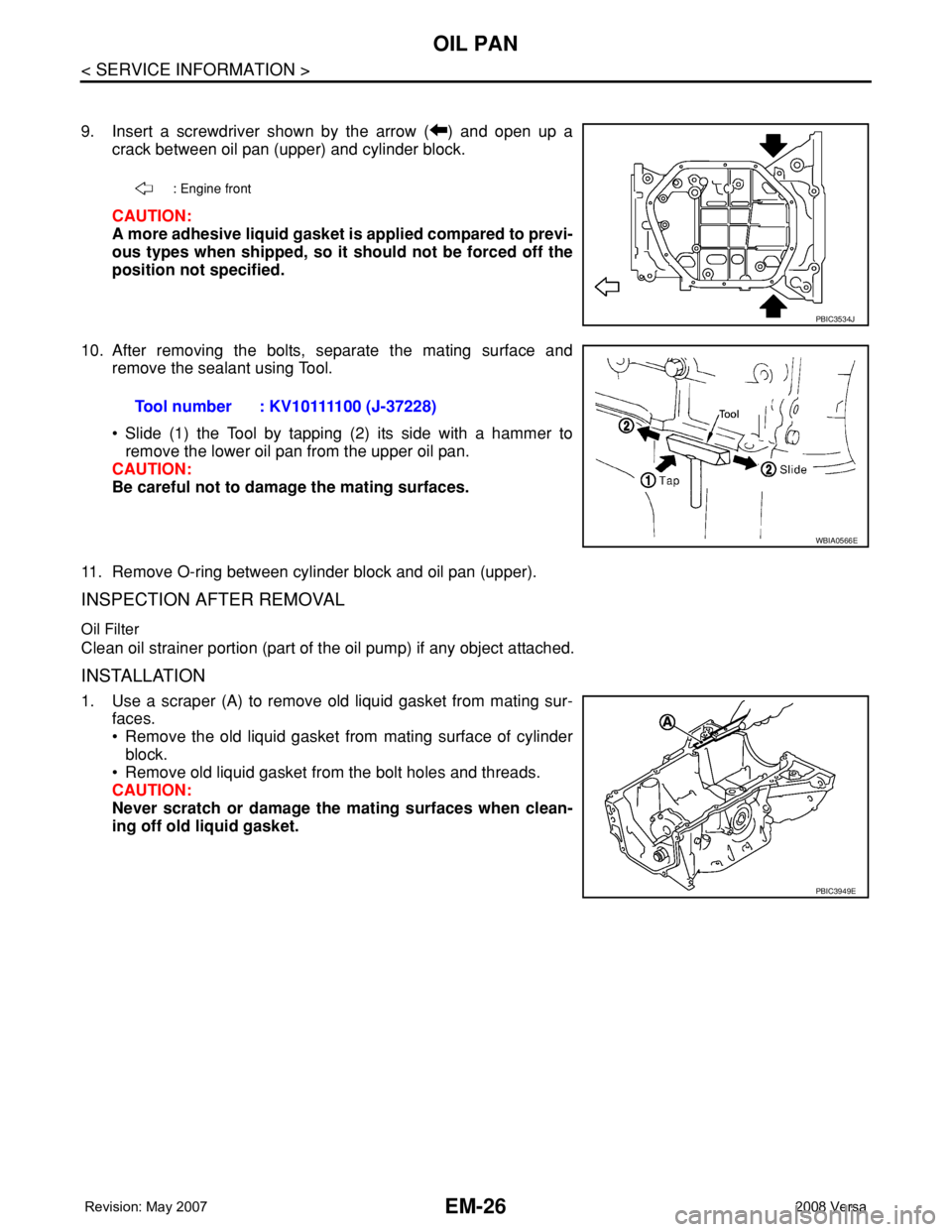
9. Insert a screwdriver shown by the arrow ( ) and open up a
crack between oil pan (upper) and cylinder block.
CAUTION:
A more adhesive liquid gasket is applied compared to previ-
ous types when shipped, so it should not be forced off the
position not specified.
10. After removing the bolts, separate the mating surface and
remove the sealant using Tool.
• Slide (1) the Tool by tapping (2) its side with a hammer to
remove the lower oil pan from the upper oil pan.
CAUTION:
Be careful not to damage the mating surfaces.
11. Remove O-ring between cylinder block and oil pan (upper).
INSPECTION AFTER REMOVAL
Oil Filter
Clean oil strainer portion (part of the oil pump) if any object attached.
INSTALLATION
1. Use a scraper (A) to remove old liquid gasket from mating sur-
faces.
• Remove the old liquid gasket from mating surface of cylinder
block.
• Remove old liquid gasket from the bolt holes and threads.
CAUTION:
Never scratch or damage the mating surfaces when clean-
ing off old liquid gasket.
: Engine front
PBIC3534J
Tool number : KV10111100 (J-37228)
WBIA0566E
PBIC3949E
Page 1709 of 2771
EM-32
< SERVICE INFORMATION >
IGNITION COIL, SPARK PLUG AND ROCKER COVER
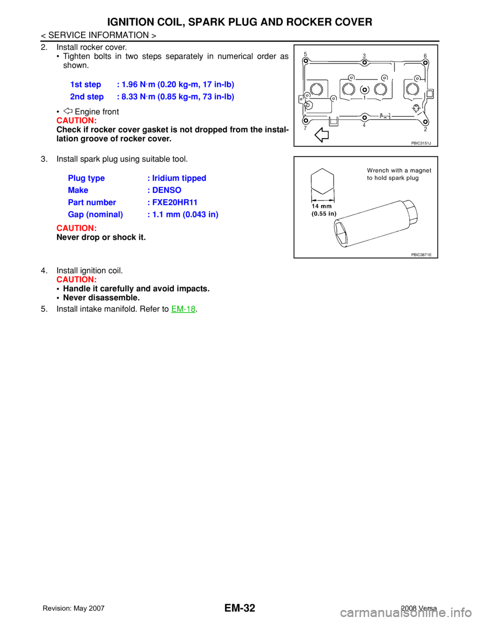
2. Install rocker cover.
• Tighten bolts in two steps separately in numerical order as
shown.
• Engine front
CAUTION:
Check if rocker cover gasket is not dropped from the instal-
lation groove of rocker cover.
3. Install spark plug using suitable tool.
CAUTION:
Never drop or shock it.
4. Install ignition coil.
CAUTION:
• Handle it carefully and avoid impacts.
• Never disassemble.
5. Install intake manifold. Refer to EM-18
. 1st step : 1.96 N·m (0.20 kg-m, 17 in-lb)
2nd step : 8.33 N·m (0.85 kg-m, 73 in-lb)
PBIC3151J
Plug type : Iridium tipped
Make : DENSO
Part number : FXE20HR11
Gap (nominal) : 1.1 mm (0.043 in)
PBIC3871E
Page 1717 of 2771
EM-40
< SERVICE INFORMATION >
TIMING CHAIN
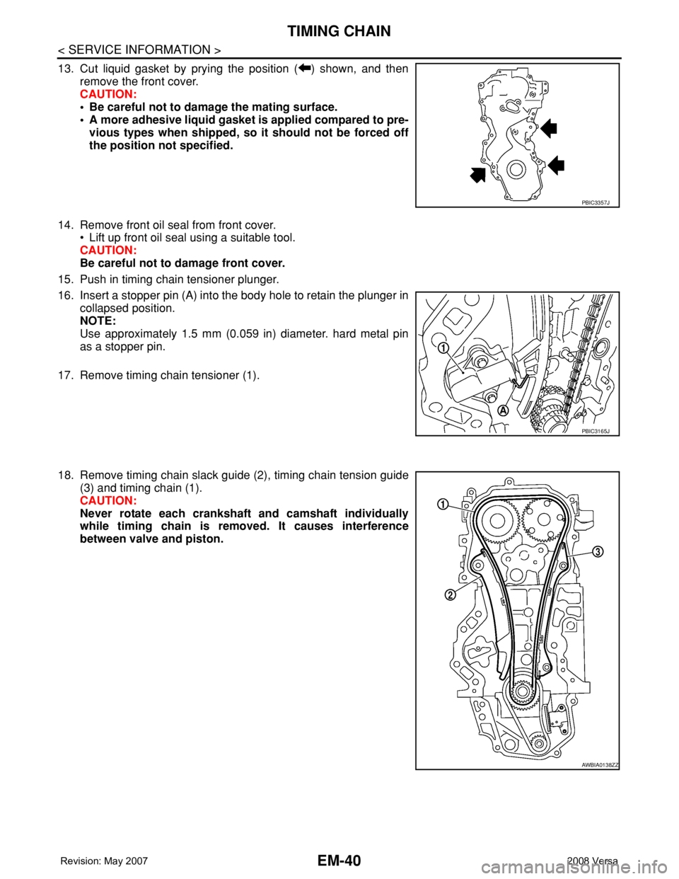
13. Cut liquid gasket by prying the position ( ) shown, and then
remove the front cover.
CAUTION:
• Be careful not to damage the mating surface.
• A more adhesive liquid gasket is applied compared to pre-
vious types when shipped, so it should not be forced off
the position not specified.
14. Remove front oil seal from front cover.
• Lift up front oil seal using a suitable tool.
CAUTION:
Be careful not to damage front cover.
15. Push in timing chain tensioner plunger.
16. Insert a stopper pin (A) into the body hole to retain the plunger in
collapsed position.
NOTE:
Use approximately 1.5 mm (0.059 in) diameter. hard metal pin
as a stopper pin.
17. Remove timing chain tensioner (1).
18. Remove timing chain slack guide (2), timing chain tension guide
(3) and timing chain (1).
CAUTION:
Never rotate each crankshaft and camshaft individually
while timing chain is removed. It causes interference
between valve and piston.
PBIC3357J
PBIC3165J
AWBIA0138ZZ
Page 1750 of 2771
ENGINE ASSEMBLY
EM-73
< SERVICE INFORMATION >
C
D
E
F
G
H
I
J
K
L
MA
EM
N
P O
• Use either 2-pole lift type or separate type lift as best you can. If board-on type is used for unavoid-
able reasons, support at the rear axle jacking point with a transmission jack or similar tool before
starting work, in preparation for the backward shift of center of gravity.
• For supporting points for lifting and jacking point at rear axle, refer to GI-38, "
Garage Jack and
Safety Stand and 2-Pole Lift".
REMOVAL
Remove the engine and the transaxle assembly from the vehicle downward. Separate the engine and the tran-
saxle.
1. Remove engine undercover
2. Drain engine coolant from radiator. Refer to CO-8, "
Changing Engine Coolant".
CAUTION:
• Perform this step when the engine is cold.
• Do not spill engine coolant on drive belt.
3. Remove front fender protector (RH and LH); Refer to EI-23
.
4. Remove exhaust front tube; Refer to EX-4
.
5. Remove drive shafts (LH and RH) from steering knuckle. Refer to FAX-8
.
6. Remove transaxle joint bolts which pierce at oil pan (upper) lower rear side. Refer to AT-226
(A/T models),
CVT-178
(CVT) or MT-16 (M/T models).
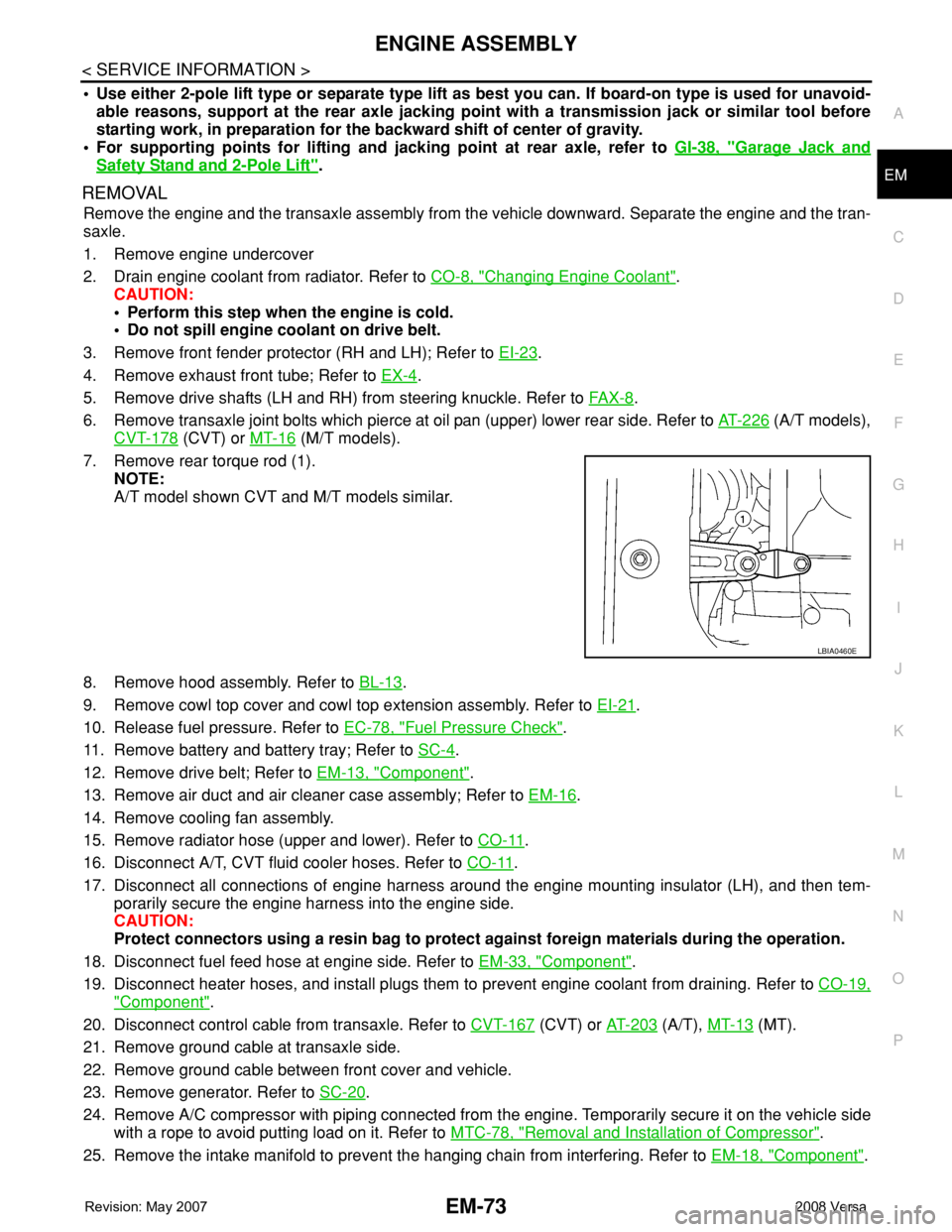
7. Remove rear torque rod (1).
NOTE:
A/T model shown CVT and M/T models similar.
8. Remove hood assembly. Refer to BL-13
.
9. Remove cowl top cover and cowl top extension assembly. Refer to EI-21
.
10. Release fuel pressure. Refer to EC-78, "
Fuel Pressure Check".
11. Remove battery and battery tray; Refer to SC-4
.
12. Remove drive belt; Refer to EM-13, "
Component".
13. Remove air duct and air cleaner case assembly; Refer to EM-16
.
14. Remove cooling fan assembly.
15. Remove radiator hose (upper and lower). Refer to CO-11
.
16. Disconnect A/T, CVT fluid cooler hoses. Refer to CO-11
.
17. Disconnect all connections of engine harness around the engine mounting insulator (LH), and then tem-
porarily secure the engine harness into the engine side.
CAUTION:
Protect connectors using a resin bag to protect against foreign materials during the operation.
18. Disconnect fuel feed hose at engine side. Refer to EM-33, "
Component".
19. Disconnect heater hoses, and install plugs them to prevent engine coolant from draining. Refer to CO-19,
"Component".
20. Disconnect control cable from transaxle. Refer to CVT-167
(CVT) or AT-203 (A/T), MT-13 (MT).
21. Remove ground cable at transaxle side.
22. Remove ground cable between front cover and vehicle.
23. Remove generator. Refer to SC-20
.
24. Remove A/C compressor with piping connected from the engine. Temporarily secure it on the vehicle side
with a rope to avoid putting load on it. Refer to MTC-78, "
Removal and Installation of Compressor".
25. Remove the intake manifold to prevent the hanging chain from interfering. Refer to EM-18, "
Component".
LBIA0460E
Page 1781 of 2771

EM-104
< SERVICE INFORMATION >
SERVICE DATA AND SPECIFICATIONS (SDS)
SERVICE DATA AND SPECIFICATIONS (SDS)
Standard and LimitINFOID:0000000001702513
GENERAL SPECIFICATIONS
DRIVE BELT
WATER CONTROL VALVE
EXHAUST MANIFOLD
Unit: mm (in)
THERMOSTAT
SPARK PLUG
Unit: mm (in)
CYLINDER HEAD
Engine typeMR18DE
Cylinder arrangementIn-line 4
Displacement
cm
3 (cu in)1,797 (109.65)
Bore and stroke mm (in) 84.0 x 81.1 (3.307 x 3.192)
Valve arrangementDOHC
Firing order1-3-4-2
Number of piston ringsCompression 2
Oil 1
Compression ratio9.9
Compression pressure
kPa (bar, kg/cm
2 , psi) / 250 rpmStandard 1,500 (15.0, 15.3, 217.6)
Minimum 1,200 (12.0, 12.2, 174)
Differential limit between cylinders 100 (1.0, 1.0, 15)
Tension of drive belt Auto adjustment by auto-tensioner
Valve opening temperature 93.5 - 96.5°C (200 - 206°F)
Maximum valve lift 8 mm/ 108°C (0.315 in/ 226°F)
Valve closing temperature More than 90°C (194°F)
Items Limit
Surface distortionEach exhaust port 0.3 (0.012)
Entire part 0.7 (0.028)
Valve opening temperature 80.5 - 83.5°C (177 - 182°F)
Maximum valve lift 8 mm/ 95°C (0.315 in/ 203°F)
Valve closing temperature More than 77°C (171°F)
Plug typeIridium-tipped TYPE
MakeDENSO
Standard typeFXE20HR11
Spark plug gapNominal: 1.1 (0.043)