2008 NISSAN TIIDA nissan connect
[x] Cancel search: nissan connectPage 1444 of 2771

EC-370
< SERVICE INFORMATION >
DTC P0455 EVAP CONTROL SYSTEM
DTC P0455 EVAP CONTROL SYSTEM
On Board Diagnosis LogicINFOID:0000000001702878
This diagnosis detects a very large leak (fuel filler cap fell off etc.) in EVAP system between the fuel tank and
EVAP canister purge volume control solenoid valve.
CAUTION:
• Use only a genuine NISSAN fuel filler cap as a replacement. If an incorrect fuel filler cap is used, the
MIL may come on.
• If the fuel filler cap is not tightened properly, the MIL may come on.
• Use only a genuine NISSAN rubber tube as a replacement.
DTC Confirmation ProcedureINFOID:0000000001702879
CAUTION:
Never remove fuel filler cap during the DTC Confirmation Procedure.
NOTE:
DTC No. Trouble diagnosis name DTC detecting condition Possible cause
P0455
0455EVAP control system
gross leak detected• EVAP control system has a very large leak
such as fuel filler cap fell off.
• EVAP control system does not operate prop-
erly.• Fuel filler cap remains open or fails to
close.
• Incorrect fuel tank vacuum relief valve
• Incorrect fuel filler cap used
• Foreign matter caught in fuel filler cap.
• Leak is in line between intake manifold
and EVAP canister purge volume control
solenoid valve.
• Foreign matter caught in EVAP canister
vent control valve.
• EVAP canister or fuel tank leaks
• EVAP purge line (pipe and rubber tube)
leaks
• EVAP purge line rubber tube bent.
• Loose or disconnected rubber tube
• EVAP canister vent control valve and the
circuit
• EVAP canister purge volume control so-
lenoid valve and the circuit
• Fuel tank temperature sensor
• O-ring of EVAP canister vent control
valve is missing or damaged.
• EVAP control system pressure sensor
• Refueling EVAP vapor cut valve
• ORVR system leaks
PBIB1026E
Page 1446 of 2771
EC-372
< SERVICE INFORMATION >
DTC P0455 EVAP CONTROL SYSTEM
5. Select Service $07 with GST.
• If P0441 is displayed on the screen, go to EC-315, "
Diagnosis Procedure" for DTC P0441.
• If P0442 is displayed on the screen, go to EC-320, "
Diagnosis Procedure" for DTC P0442.
• If P0455 is displayed on the screen, go to EC-372, "
Diagnosis Procedure".
Diagnosis ProcedureINFOID:0000000001702880
1.CHECK FUEL FILLER CAP DESIGN
1. Turn ignition switch OFF.
2. Check for genuine NISSAN fuel filler cap design.
OK or NG
OK >> GO TO 2.
NG >> Replace with genuine NISSAN fuel filler cap.
2.CHECK FUEL FILLER CAP INSTALLATION
Check that the cap is tightened properly by rotating the cap clockwise.
OK or NG
OK >> GO TO 3.
NG >> 1. Open fuel filler cap, then clean cap and fuel filler neck threads using air blower.
2. Retighten until reteaching sound is heard.
3.CHECK FUEL FILLER CAP FUNCTION
Check for air releasing sound while opening the fuel filler cap.
OK or NG
OK >> GO TO 5.
NG >> GO TO 4.
4.CHECK FUEL TANK VACUUM RELIEF VALVE
Refer to EC-33, "
Component Inspection".
OK or NG
OK >> GO TO 5.
NG >> Replace fuel filler cap with a genuine one.
5.CHECK EVAP PURGE LINE
Check EVAP purge line (pipe, rubber tube, fuel tank and EVAP canister) for cracks, improper connection or
disconnection.
Refer to EC-31
.
OK or NG
OK >> GO TO 6.
NG >> Repair or reconnect the hose.
6.CLEAN EVAP PURGE LINE
Clean EVAP purge line (pipe and rubber tube) using air blower.
>> GO TO 7.
7.CHECK EVAP CANISTER VENT CONTROL VALVE
Check the following.
• EVAP canister vent control is installed properly.
Refer to EC-35, "
Removal and Installation".
• EVAP canister vent control valve.
SEF915U
Page 1451 of 2771
DTC P0456 EVAP CONTROL SYSTEM
EC-377
< SERVICE INFORMATION >
C
D
E
F
G
H
I
J
K
L
MA
EC
N
P O
DTC P0456 EVAP CONTROL SYSTEM
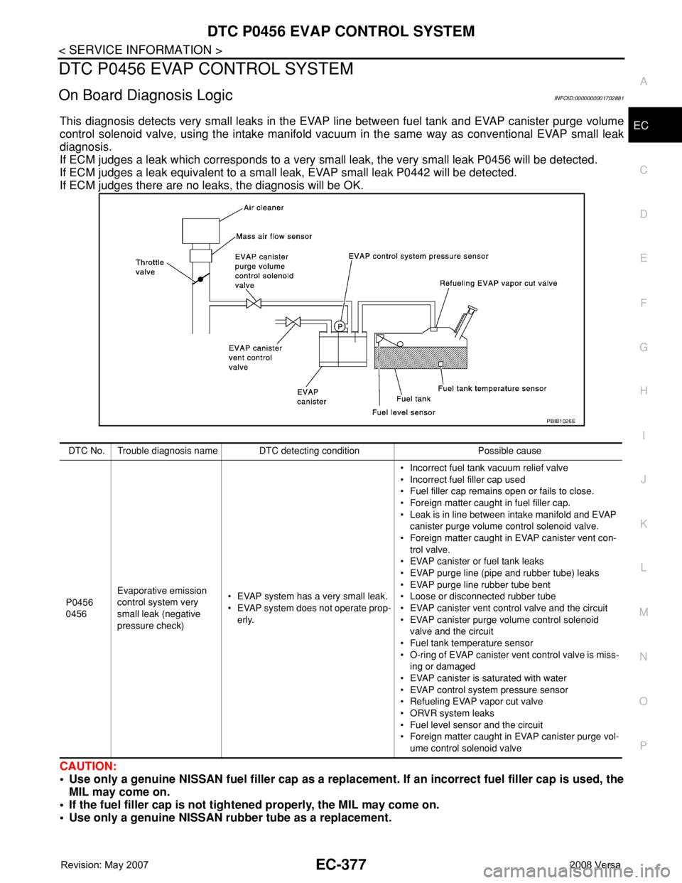
On Board Diagnosis LogicINFOID:0000000001702881
This diagnosis detects very small leaks in the EVAP line between fuel tank and EVAP canister purge volume
control solenoid valve, using the intake manifold vacuum in the same way as conventional EVAP small leak
diagnosis.
If ECM judges a leak which corresponds to a very small leak, the very small leak P0456 will be detected.
If ECM judges a leak equivalent to a small leak, EVAP small leak P0442 will be detected.
If ECM judges there are no leaks, the diagnosis will be OK.
CAUTION:
• Use only a genuine NISSAN fuel filler cap as a replacement. If an incorrect fuel filler cap is used, the
MIL may come on.
• If the fuel filler cap is not tightened properly, the MIL may come on.
• Use only a genuine NISSAN rubber tube as a replacement.
DTC No. Trouble diagnosis name DTC detecting condition Possible cause
P0456
0456Evaporative emission
control system very
small leak (negative
pressure check)• EVAP system has a very small leak.
• EVAP system does not operate prop-
erly.• Incorrect fuel tank vacuum relief valve
• Incorrect fuel filler cap used
• Fuel filler cap remains open or fails to close.
• Foreign matter caught in fuel filler cap.
• Leak is in line between intake manifold and EVAP
canister purge volume control solenoid valve.
• Foreign matter caught in EVAP canister vent con-
trol valve.
• EVAP canister or fuel tank leaks
• EVAP purge line (pipe and rubber tube) leaks
• EVAP purge line rubber tube bent
• Loose or disconnected rubber tube
• EVAP canister vent control valve and the circuit
• EVAP canister purge volume control solenoid
valve and the circuit
• Fuel tank temperature sensor
• O-ring of EVAP canister vent control valve is miss-
ing or damaged
• EVAP canister is saturated with water
• EVAP control system pressure sensor
• Refueling EVAP vapor cut valve
• ORVR system leaks
• Fuel level sensor and the circuit
• Foreign matter caught in EVAP canister purge vol-
ume control solenoid valve
PBIB1026E
Page 1453 of 2771
DTC P0456 EVAP CONTROL SYSTEM
EC-379
< SERVICE INFORMATION >
C
D
E
F
G
H
I
J
K
L
MA
EC
N
P O
• Do not exceeded 4.12 kPa (0.042 kg/cm2, 0.6 psi).
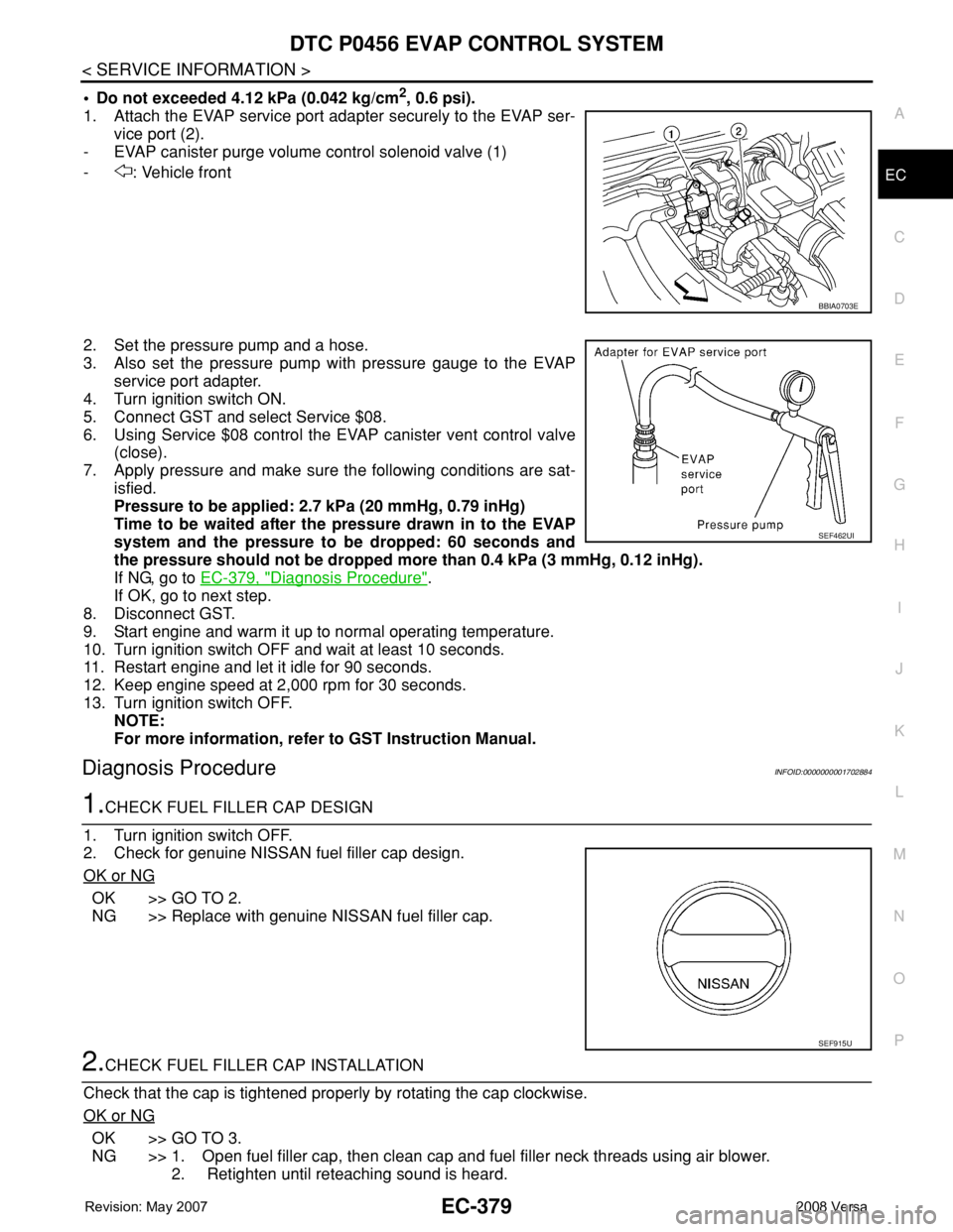
1. Attach the EVAP service port adapter securely to the EVAP ser-
vice port (2).
- EVAP canister purge volume control solenoid valve (1)
- : Vehicle front
2. Set the pressure pump and a hose.
3. Also set the pressure pump with pressure gauge to the EVAP
service port adapter.
4. Turn ignition switch ON.
5. Connect GST and select Service $08.
6. Using Service $08 control the EVAP canister vent control valve
(close).
7. Apply pressure and make sure the following conditions are sat-
isfied.
Pressure to be applied: 2.7 kPa (20 mmHg, 0.79 inHg)
Time to be waited after the pressure drawn in to the EVAP
system and the pressure to be dropped: 60 seconds and
the pressure should not be dropped more than 0.4 kPa (3 mmHg, 0.12 inHg).
If NG, go to EC-379, "
Diagnosis Procedure".
If OK, go to next step.
8. Disconnect GST.
9. Start engine and warm it up to normal operating temperature.
10. Turn ignition switch OFF and wait at least 10 seconds.
11. Restart engine and let it idle for 90 seconds.
12. Keep engine speed at 2,000 rpm for 30 seconds.
13. Turn ignition switch OFF.
NOTE:
For more information, refer to GST Instruction Manual.
Diagnosis ProcedureINFOID:0000000001702884
1.CHECK FUEL FILLER CAP DESIGN
1. Turn ignition switch OFF.
2. Check for genuine NISSAN fuel filler cap design.
OK or NG
OK >> GO TO 2.
NG >> Replace with genuine NISSAN fuel filler cap.
2.CHECK FUEL FILLER CAP INSTALLATION
Check that the cap is tightened properly by rotating the cap clockwise.
OK or NG
OK >> GO TO 3.
NG >> 1. Open fuel filler cap, then clean cap and fuel filler neck threads using air blower.
2. Retighten until reteaching sound is heard.
BBIA0703E
SEF462UI
SEF915U
Page 1626 of 2771
PRECAUTIONS
EI-3
< PRECAUTION >
C
D
E
F
G
H
J
K
L
MA
B
EI
N
O
P
PRECAUTION
PRECAUTIONS
Precaution for Supplemental Restraint System (SRS) "AIR BAG" and "SEAT BELT
PRE-TENSIONER"
INFOID:0000000001704210
The Supplemental Restraint System such as “AIR BAG” and “SEAT BELT PRE-TENSIONER”, used along
with a front seat belt, helps to reduce the risk or severity of injury to the driver and front passenger for certain
types of collision. This system includes seat belt switch inputs and dual stage front air bag modules. The SRS
system uses the seat belt switches to determine the front air bag deployment, and may only deploy one front
air bag, depending on the severity of a collision and whether the front occupants are belted or unbelted.
Information necessary to service the system safely is included in the SR and SB section of this Service Man-
ual.
WARNING:
• To avoid rendering the SRS inoperative, which could increase the risk of personal injury or death in
the event of a collision which would result in air bag inflation, all maintenance must be performed by
an authorized NISSAN/INFINITI dealer.
• Improper maintenance, including incorrect removal and installation of the SRS, can lead to personal
injury caused by unintentional activation of the system. For removal of Spiral Cable and Air Bag
Module, see the SR section.
• Do not use electrical test equipment on any circuit related to the SRS unless instructed to in this
Service Manual. SRS wiring harnesses can be identified by yellow and/or orange harnesses or har-
ness connectors.
PrecautionINFOID:0000000001704211
• When removing or disassembling any part, be careful not to damage or deform it. Protect parts which may
get in the way with cloth.
• When removing parts with a screwdriver or other tool, protect parts by wrapping them with vinyl or tape.
• Keep removed parts protected with cloth.
• If a clip is deformed or damaged, replace it.
• If an unreusable part is removed, replace it with a new one.
• Tighten bolts and nuts firmly to the specified torque.
• After re-assembly has been completed, make sure each part functions correctly.
• Remove stains in the following way.
- Water-soluble stains:
Dip a cloth in warm water, and squeeze tightly. After wiping the stain, wipe with a soft dry cloth.
- Oil stain:
Dissolve a synthetic detergent in warm water (density of 2 to 3% or less), dip the cloth, then clean off the
stain with the cloth. Next, dip the soft cloth in fresh water, and then squeeze it tightly. Then clean off the
detergent completely. Then wipe the area with a soft dry cloth.
• Do not use any organic solvent, such as thinner or benzine.
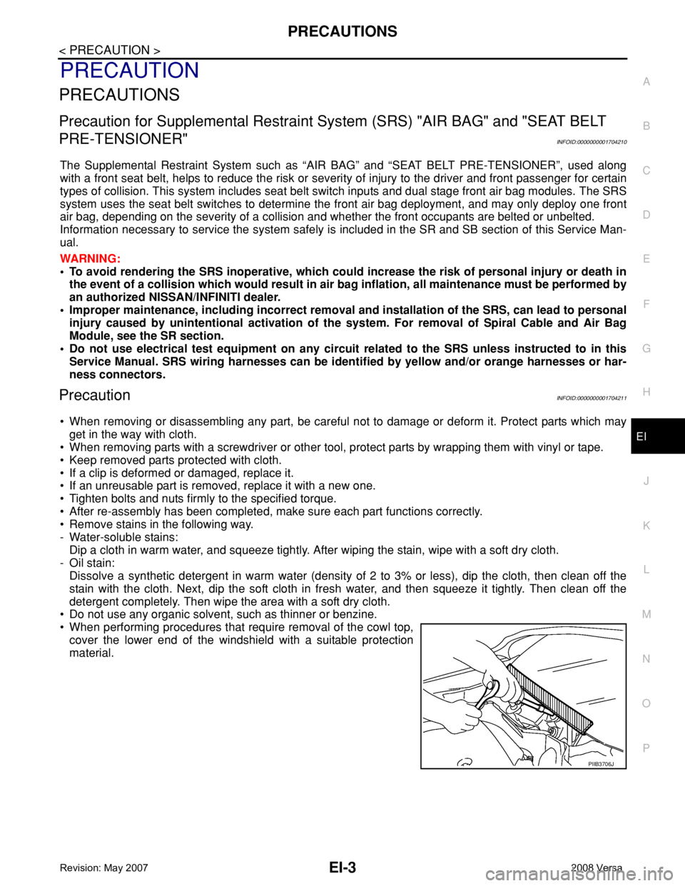
• When performing procedures that require removal of the cowl top,
cover the lower end of the windshield with a suitable protection
material.
PIIB3706J
Page 1629 of 2771

EI-6
< SYMPTOM DIAGNOSIS >
SQUEAK AND RATTLE TROUBLE DIAGNOSIS
If possible, drive the vehicle with the customer until the noise is duplicated. Note any additional information on
the Diagnostic Worksheet regarding the conditions or location of the noise. This information can be used to
duplicate the same conditions when you confirm the repair.
If the noise can be duplicated easily during the test drive, to help identify the source of the noise, try to dupli-
cate the noise with the vehicle stopped by doing one or all of the following:
• Close a door.
• Tap or push/pull around the area where the noise appears to be coming from.
• Rev the engine.
• Use a floor jack to recreate vehicle “twist”.
• At idle, apply engine load (electrical load, half-clutch on M/T model, drive position on A/T model).
• Raise the vehicle on a hoist and hit a tire with a rubber hammer.
• Drive the vehicle and attempt to duplicate the conditions the customer states exist when the noise occurs.
• If it is difficult to duplicate the noise, drive the vehicle slowly on an undulating or rough road to stress the
vehicle body.
CHECK RELATED SERVICE BULLETINS
After verifying the customer concern or symptom, check ASIST for Technical Service Bulletins (TSBs) related
to that concern or symptom.
If a TSB relates to the symptom, follow the procedure to repair the noise.
LOCATE THE NOISE AND IDENTIFY THE ROOT CAUSE
1. Narrow down the noise to a general area. To help pinpoint the source of the noise, use a listening tool
(Chassis Ear: J-39570, Engine Ear: J-39565 and mechanics stethoscope).
2. Narrow down the noise to a more specific area and identify the cause of the noise by:
• Removing the components in the area that you suspect the noise is coming from.
Do not use too much force when removing clips and fasteners, otherwise clips and fasteners
can be broken or lost during the repair, resulting in the creation of new noise.
• Tapping or pushing/pulling the component that you suspect is causing the noise.
Do not tap or push/pull the component with excessive force, otherwise the noise will be elimi-
nated only temporarily.
• Feeling for a vibration with your hand by touching the component(s) that you suspect is (are) causing
the noise.
• Placing a piece of paper between components that you suspect are causing the noise.
• Looking for loose components and contact marks.
Refer to EI-7, "
Generic Squeak and Rattle Troubleshooting".
REPAIR THE CAUSE
• If the cause is a loose component, tighten the component securely.
• If the cause is insufficient clearance between components:
- Separate components by repositioning or loosening and retightening the component, if possible.
- Insulate components with a suitable insulator such as urethane pads, foam blocks, felt cloth tape or ure-
thane tape. A NISSAN Squeak and Rattle Kit (J-43980) is available through your authorized NISSAN Parts
Department.
CAUTION:
Do not use excessive force as many components are constructed of plastic and may be damaged.
Always check with the Parts Department for the latest parts information.
The following materials are contained in the NISSAN Squeak and Rattle Kit (J-43980). Each item can be
ordered separately as needed.
URETHANE PADS [1.5 mm (0.059 in) thick]
Insulates connectors, harness, etc.
76268-9E005: 100 x 135 mm (3.94 x 5.31 in)/76884-71L01: 60 x 85 mm (2.36 x 3.35 in)/76884-71L02: 15 x 25
mm (0.59 x 0.98 in)
INSULATOR (Foam blocks)
Insulates components from contact. Can be used to fill space behind a panel.
73982-9E000: 45 mm (1.77 in) thick, 50 x 50 mm (1.97 x 1.97 in)/73982-50Y00: 10 mm (0.39 in) thick, 50 x 50
mm (1.97 x 1.97 in)
INSULATOR (Light foam block)
80845-71L00: 30 mm (1.18 in) thick, 30 x 50 mm (1.18 x 1.97 in)
FELT CLOTH TAPE
Used to insulate where movement does not occur. Ideal for instrument panel applications.
68370-4B000: 15 x 25 mm (0.59 x 0.98 in) pad/68239-13E00: 5 mm (0.20 in) wide tape roll
Page 1680 of 2771
PRECAUTIONS
EM-3
< SERVICE INFORMATION >
C
D
E
F
G
H
I
J
K
L
MA
EM
N
P O
SERVICE INFORMATION
PRECAUTIONS
Precaution for Supplemental Restraint System (SRS) "AIR BAG" and "SEAT BELT
PRE-TENSIONER"
INFOID:0000000001702460
The Supplemental Restraint System such as “AIR BAG” and “SEAT BELT PRE-TENSIONER”, used along
with a front seat belt, helps to reduce the risk or severity of injury to the driver and front passenger for certain
types of collision. This system includes seat belt switch inputs and dual stage front air bag modules. The SRS
system uses the seat belt switches to determine the front air bag deployment, and may only deploy one front
air bag, depending on the severity of a collision and whether the front occupants are belted or unbelted.
Information necessary to service the system safely is included in the SRS and SB section of this Service Man-
ual.
WARNING:
• To avoid rendering the SRS inoperative, which could increase the risk of personal injury or death in
the event of a collision which would result in air bag inflation, all maintenance must be performed by
an authorized NISSAN/INFINITI dealer.
• Improper maintenance, including incorrect removal and installation of the SRS, can lead to personal
injury caused by unintentional activation of the system. For removal of Spiral Cable and Air Bag
Module, see the SRS section.
• Do not use electrical test equipment on any circuit related to the SRS unless instructed to in this
Service Manual. SRS wiring harnesses can be identified by yellow and/or orange harnesses or har-
ness connectors.
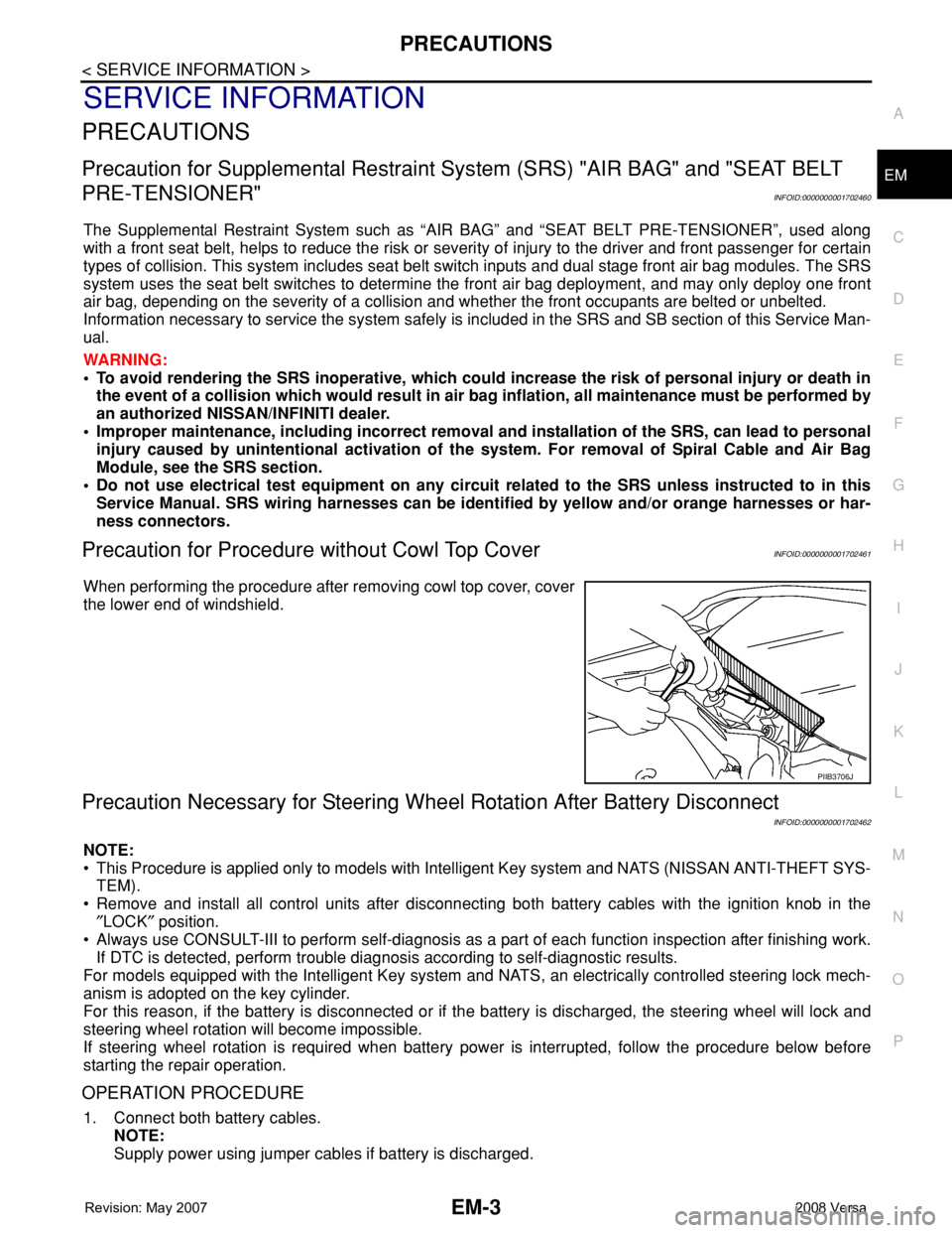
Precaution for Procedure without Cowl Top CoverINFOID:0000000001702461
When performing the procedure after removing cowl top cover, cover
the lower end of windshield.
Precaution Necessary for Steering Wheel Rotation After Battery Disconnect
INFOID:0000000001702462
NOTE:
• This Procedure is applied only to models with Intelligent Key system and NATS (NISSAN ANTI-THEFT SYS-
TEM).
• Remove and install all control units after disconnecting both battery cables with the ignition knob in the
″LOCK″ position.
• Always use CONSULT-III to perform self-diagnosis as a part of each function inspection after finishing work.
If DTC is detected, perform trouble diagnosis according to self-diagnostic results.
For models equipped with the Intelligent Key system and NATS, an electrically controlled steering lock mech-
anism is adopted on the key cylinder.
For this reason, if the battery is disconnected or if the battery is discharged, the steering wheel will lock and
steering wheel rotation will become impossible.
If steering wheel rotation is required when battery power is interrupted, follow the procedure below before
starting the repair operation.
OPERATION PROCEDURE
1. Connect both battery cables.
NOTE:
Supply power using jumper cables if battery is discharged.
PIIB3706J
Page 1793 of 2771

EX-2
< SERVICE INFORMATION >
PRECAUTIONS
SERVICE INFORMATION
PRECAUTIONS
Precaution for Supplemental Restraint System (SRS) "AIR BAG" and "SEAT BELT
PRE-TENSIONER"
INFOID:0000000001830414
The Supplemental Restraint System such as “AIR BAG” and “SEAT BELT PRE-TENSIONER”, used along
with a front seat belt, helps to reduce the risk or severity of injury to the driver and front passenger for certain
types of collision. This system includes seat belt switch inputs and dual stage front air bag modules. The SRS
system uses the seat belt switches to determine the front air bag deployment, and may only deploy one front
air bag, depending on the severity of a collision and whether the front occupants are belted or unbelted.
Information necessary to service the system safely is included in the SRS and SB section of this Service Man-
ual.
WARNING:
• To avoid rendering the SRS inoperative, which could increase the risk of personal injury or death in
the event of a collision which would result in air bag inflation, all maintenance must be performed by
an authorized NISSAN/INFINITI dealer.
• Improper maintenance, including incorrect removal and installation of the SRS, can lead to personal
injury caused by unintentional activation of the system. For removal of Spiral Cable and Air Bag
Module, see the SRS section.
• Do not use electrical test equipment on any circuit related to the SRS unless instructed to in this
Service Manual. SRS wiring harnesses can be identified by yellow and/or orange harnesses or har-
ness connectors.