2008 NISSAN TIIDA nissan connect
[x] Cancel search: nissan connectPage 438 of 2771

BL-4
< SERVICE INFORMATION >
PRECAUTIONS
SERVICE INFORMATION
PRECAUTIONS
Precaution for Supplemental Restraint System (SRS) "AIR BAG" and "SEAT BELT
PRE-TENSIONER"
INFOID:0000000001703938
The Supplemental Restraint System such as “AIR BAG” and “SEAT BELT PRE-TENSIONER”, used along
with a front seat belt, helps to reduce the risk or severity of injury to the driver and front passenger for certain
types of collision. This system includes seat belt switch inputs and dual stage front air bag modules. The SRS
system uses the seat belt switches to determine the front air bag deployment, and may only deploy one front
air bag, depending on the severity of a collision and whether the front occupants are belted or unbelted.
Information necessary to service the system safely is included in the SRS and SB section of this Service Man-
ual.
WARNING:
• To avoid rendering the SRS inoperative, which could increase the risk of personal injury or death in
the event of a collision which would result in air bag inflation, all maintenance must be performed by
an authorized NISSAN/INFINITI dealer.
• Improper maintenance, including incorrect removal and installation of the SRS, can lead to personal
injury caused by unintentional activation of the system. For removal of Spiral Cable and Air Bag
Module, see the SRS section.
• Do not use electrical test equipment on any circuit related to the SRS unless instructed to in this
Service Manual. SRS wiring harnesses can be identified by yellow and/or orange harnesses or har-
ness connectors.
Precaution Necessary for Steering Wheel Rotation After Battery Disconnect
INFOID:0000000001703939
NOTE:
• This procedure is applied only to models with Intelligent Key system and NVIS/IVIS (NISSAN/INFINITI
VEHICLE IMMOBILIZER SYSTEM - NATS).
• Remove and install all control units after disconnecting both battery cables with the ignition in the ″LOCK″
position.
• Always use CONSULT-III to perform self-diagnosis as a part of each function inspection after finishing work.
If DTC is detected, perform trouble diagnosis according to self-diagnostic results.
For models equipped with the Intelligent Key system and NVIS/IVIS, an electrically controlled steering lock
mechanism is adopted on the key cylinder.
For this reason, if the battery is disconnected or if the battery is discharged, the steering wheel will lock and
steering wheel rotation will become impossible.
If steering wheel rotation is required when battery power is interrupted, follow the procedure below before
starting the repair operation.
OPERATION PROCEDURE
1. Connect both battery cables.
NOTE:
Supply power using jumper cables if battery is discharged.
2. Use the Intelligent Key or mechanical key to turn the ignition switch to the ″ACC″ position. At this time, the
steering lock will be released.
3. Disconnect both battery cables. The steering lock will remain released and the steering wheel can be
rotated.
4. Perform the necessary repair operation.
5. When the repair work is completed, return the ignition switch to the ″LOCK″ position before connecting
the battery cables. (At this time, the steering lock mechanism will engage.)
6. Perform a self-diagnosis check of all control units using CONSULT-III.
Page 442 of 2771

BL-8
< SERVICE INFORMATION >
SQUEAK AND RATTLE TROUBLE DIAGNOSES
If the noise can be duplicated easily during the test drive, to help identify the source of the noise, try to dupli-
cate the noise with the vehicle stopped by doing one or all of the following:
1) Close a door.
2) Tap or push/pull around the area where the noise appears to be coming from.
3) Rev the engine.
4) Use a floor jack to recreate vehicle “twist”.
5) At idle, apply engine load (electrical load, half-clutch on M/T model, drive position on A/T model).
6) Raise the vehicle on a hoist and hit a tire with a rubber hammer.
• Drive the vehicle and attempt to duplicate the conditions the customer states exist when the noise occurs.
• If it is difficult to duplicate the noise, drive the vehicle slowly on an undulating or rough road to stress the
vehicle body.
CHECK RELATED SERVICE BULLETINS
After verifying the customer concern or symptom, check ASIST for Technical Service Bulletins (TSBs) related
to that concern or symptom.
If a TSB relates to the symptom, follow the procedure to repair the noise.
LOCATE THE NOISE AND IDENTIFY THE ROOT CAUSE
1. Narrow down the noise to a general area.To help pinpoint the source of the noise, use a listening tool
(Chassis Ear: J-39570, Engine Ear: J-39565 and mechanic's stethoscope).
2. Narrow down the noise to a more specific area and identify the cause of the noise by:
• removing the components in the area that you suspect the noise is coming from.
Do not use too much force when removing clips and fasteners, otherwise clips and fasteners can be broken
or lost during the repair, resulting in the creation of new noise.
• tapping or pushing/pulling the component that you suspect is causing the noise.
Do not tap or push/pull the component with excessive force, otherwise the noise will be eliminated only tem-
porarily.
• feeling for a vibration with your hand by touching the component(s) that you suspect is (are) causing the
noise.
• placing a piece of paper between components that you suspect are causing the noise.
• looking for loose components and contact marks.
Refer to BL-9, "
Generic Squeak and Rattle Troubleshooting".
REPAIR THE CAUSE
• If the cause is a loose component, tighten the component securely.
• If the cause is insufficient clearance between components:
- separate components by repositioning or loosening and retightening the component, if possible.
- insulate components with a suitable insulator such as urethane pads, foam blocks, felt cloth tape or urethane
tape. A NISSAN Squeak and Rattle Kit (J-43980) is available through your authorized NISSAN Parts Depart-
ment.
CAUTION:
Do not use excessive force as many components are constructed of plastic and may be damaged.
Always check with the Parts Department for the latest parts information.
The following materials are contained in the NISSAN Squeak and Rattle Kit (J-43980). Each item can be
ordered separately as needed.
URETHANE PADS [1.5 mm (0.059 in) thick]
Insulates connectors, harness, etc.
76268-9E005: 100×135 mm (3.94×5.31 in)/76884-71L01: 60×85 mm (2.36×3.35 in)/76884-71L02: 15×25
mm (0.59×0.98 in)
INSULATOR (Foam blocks)
Insulates components from contact. Can be used to fill space behind a panel.
73982-9E000: 45 mm (1.77 in) thick, 50×50 mm (1.97×1.97 in)/73982-50Y00: 10 mm (0.39 in) thick,
50×50 mm (1.97×1.97 in)
INSULATOR (Light foam block)
80845-71L00: 30 mm (1.18 in) thick, 30×50 mm (1.18×1.97 in)
FELT CLOTH TAPE
Used to insulate where movement does not occur. Ideal for instrument panel applications.
68370-4B000: 15×25 mm (0.59×0.98 in) pad/68239-13E00: 5 mm (0.20 in) wide tape roll. The following
materials not found in the kit can also be used to repair squeaks and rattles.
UHMW (TEFLON) TAPE
Insulates where slight movement is present. Ideal for instrument panel applications.
Page 644 of 2771
BL-210
< SERVICE INFORMATION >
NATS (NISSAN ANTI-THEFT SYSTEM)
NATS (NISSAN ANTI-THEFT SYSTEM)
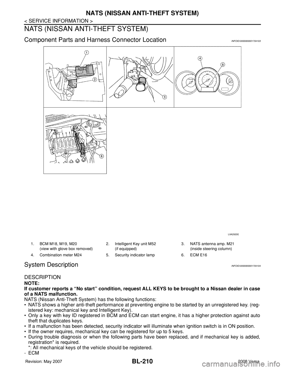
Component Parts and Harness Connector LocationINFOID:0000000001704103
System DescriptionINFOID:0000000001704104
DESCRIPTION
NOTE:
If customer reports a “No start” condition, request ALL KEYS to be brought to a Nissan dealer in case
of a NATS malfunction.
NATS (Nissan Anti-Theft System) has the following functions:
• NATS shows a higher anti-theft performance at preventing engine to be started by an unregistered key. (reg-
istered key: mechanical key and Intelligent Key).
• Only a key with key ID registered in BCM and ECM can start engine, it has a higher protection against auto
theft that duplicates keys.
• If a malfunction has been detected, security indicator will illuminate when ignition switch is in ON position.
• If the owner requires, mechanical key can be registered for up to 5 keys.
• During trouble diagnosis or when the following parts have been replaced, and if mechanical key is added,
registration* is required.
*: All mechanical keys of the vehicle should be registered.
-ECM
LIIA2920E
1. BCM M18, M19, M20
(view with glove box removed)2. Intelligent Key unit M52
(if equipped)3. NATS antenna amp. M21
(inside steering column)
4. Combination meter M24 5. Security indicator lamp 6. ECM E16
Page 648 of 2771
BL-214
< SERVICE INFORMATION >
NATS (NISSAN ANTI-THEFT SYSTEM)
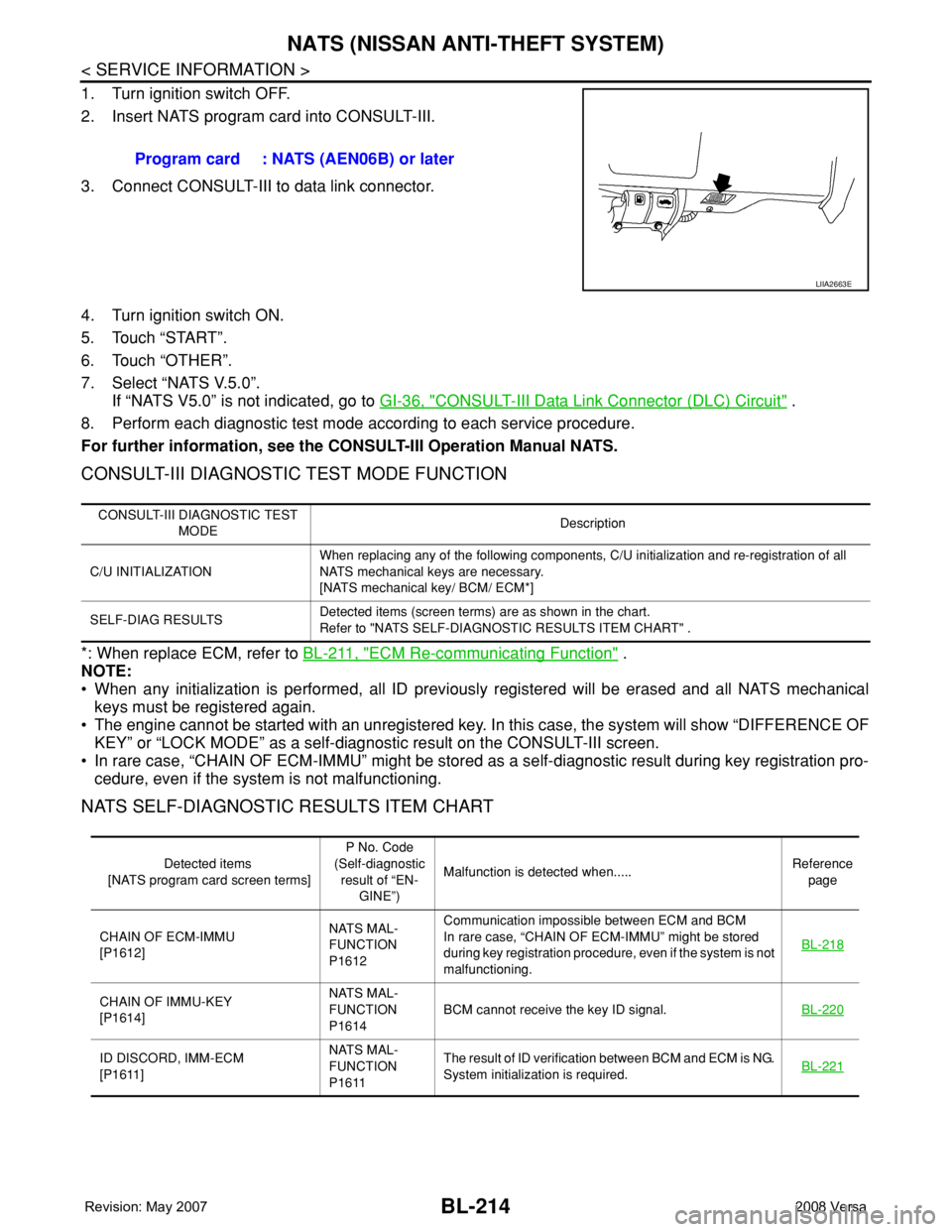
1. Turn ignition switch OFF.
2. Insert NATS program card into CONSULT-III.
3. Connect CONSULT-III to data link connector.
4. Turn ignition switch ON.
5. Touch “START”.
6. Touch “OTHER”.
7. Select “NATS V.5.0”.
If “NATS V5.0” is not indicated, go to GI-36, "
CONSULT-III Data Link Connector (DLC) Circuit" .
8. Perform each diagnostic test mode according to each service procedure.
For further information, see the CONSULT-III Operation Manual NATS.
CONSULT-III DIAGNOSTIC TEST MODE FUNCTION
*: When replace ECM, refer to BL-211, "ECM Re-communicating Function" .
NOTE:
• When any initialization is performed, all ID previously registered will be erased and all NATS mechanical
keys must be registered again.
• The engine cannot be started with an unregistered key. In this case, the system will show “DIFFERENCE OF
KEY” or “LOCK MODE” as a self-diagnostic result on the CONSULT-III screen.
• In rare case, “CHAIN OF ECM-IMMU” might be stored as a self-diagnostic result during key registration pro-
cedure, even if the system is not malfunctioning.
NATS SELF-DIAGNOSTIC RESULTS ITEM CHART
Program card : NATS (AEN06B) or later
LIIA2663E
CONSULT-III DIAGNOSTIC TEST
MODEDescription
C/U INITIALIZATIONWhen replacing any of the following components, C/U initialization and re-registration of all
NATS mechanical keys are necessary.
[NATS mechanical key/ BCM/ ECM*]
SELF-DIAG RESULTSDetected items (screen terms) are as shown in the chart.
Refer to "NATS SELF-DIAGNOSTIC RESULTS ITEM CHART" .
Detected items
[NATS program card screen terms]P No. Code
(Self-diagnostic
result of “EN-
GINE”)Malfunction is detected when.....Reference
page
CHAIN OF ECM-IMMU
[P1612]NATS MAL-
FUNCTION
P1612Communication impossible between ECM and BCM
In rare case, “CHAIN OF ECM-IMMU” might be stored
during key registration procedure, even if the system is not
malfunctioning.BL-218
CHAIN OF IMMU-KEY
[P1614]NATS MAL-
FUNCTION
P1614BCM cannot receive the key ID signal.BL-220
ID DISCORD, IMM-ECM
[P1611]NATS MAL-
FUNCTION
P1611The result of ID verification between BCM and ECM is NG.
System initialization is required.BL-221
Page 653 of 2771
NATS (NISSAN ANTI-THEFT SYSTEM)
BL-219
< SERVICE INFORMATION >
C
D
E
F
G
H
J
K
L
MA
B
BL
N
O
P
In rare case, “CHAIN OF ECM-IMMU” might be stored during key registration procedure, even if the system is
not malfunctioning.
Is
“CHAIN OF ECM-IMMU” displayed?
Yes >> GO TO 2.
No >> GO TO BL-217, "
Trouble Diagnosis" .
2.CHECK POWER SUPPLY CIRCUIT FOR BCM
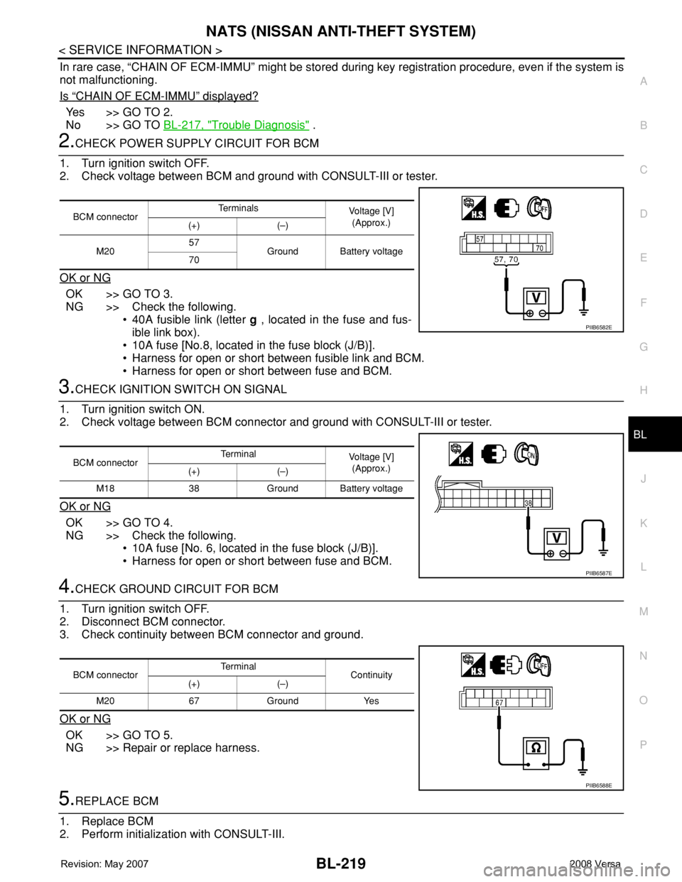
1. Turn ignition switch OFF.
2. Check voltage between BCM and ground with CONSULT-III or tester.
OK or NG
OK >> GO TO 3.
NG >> Check the following.
• 40A fusible link (letter g , located in the fuse and fus-
ible link box).
• 10A fuse [No.8, located in the fuse block (J/B)].
• Harness for open or short between fusible link and BCM.
• Harness for open or short between fuse and BCM.
3.CHECK IGNITION SWITCH ON SIGNAL
1. Turn ignition switch ON.
2. Check voltage between BCM connector and ground with CONSULT-III or tester.
OK or NG
OK >> GO TO 4.
NG >> Check the following.
• 10A fuse [No. 6, located in the fuse block (J/B)].
• Harness for open or short between fuse and BCM.
4.CHECK GROUND CIRCUIT FOR BCM
1. Turn ignition switch OFF.
2. Disconnect BCM connector.
3. Check continuity between BCM connector and ground.
OK or NG
OK >> GO TO 5.
NG >> Repair or replace harness.
5.REPLACE BCM
1. Replace BCM
2. Perform initialization with CONSULT-III.
BCM connectorTe r m i n a l s
Voltage [V]
(Approx.)
(+) (–)
M2057
Ground Battery voltage
70
PIIB6582E
BCM connectorTerminal
Voltage [V]
(Approx.)
(+) (–)
M18 38 Ground Battery voltage
PIIB6587E
BCM connectorTerminal
Continuity
(+) (–)
M20 67 Ground Yes
PIIB6588E
Page 654 of 2771
BL-220
< SERVICE INFORMATION >
NATS (NISSAN ANTI-THEFT SYSTEM)
For initialization, refer to “CONSULT-III Operation Manual NATS”.
Does the engine start?
Yes >> BCM is malfunctioning.
• Replace BCM. Refer to BCS-18, "
Removal and Installation of BCM" .
• Perform initialization with CONSULT-III
• For initialization, refer to “CONSULT-III Operation Manual NATS”
No >> ECM is malfunctioning.
• Replace ECM.
• Perform initialization or re-communicating function
• For initialization, refer to “CONSULT-III Operation Manual NATS”
• For re-communicating function, refer to BL-211, "
ECM Re-communicating Function"
Diagnosis Procedure 2INFOID:0000000001704113
Self-diagnostic results:
“CHAIN OF IMMU-KEY” displayed on CONSULT-III screen
1.CONFIRM SELF-DIAGNOSTIC RESULTS
Confirm SELF-DIAGNOSTIC RESULTS “CHAIN OF IMMU-KEY” displayed on CONSULT-III screen.
Is
“CHAIN OF IMMU-KEY” displayed?
Ye s > > G O T O 2 .
No >> GO TO BL-217, "
Trouble Diagnosis" .
2.CHECK NATS ANTENNA AMP. INSTALLATION
Check NATS antenna amp. installation. Refer to BL-224, "
How to Replace NATS Antenna Amp" .
OK or NG
OK >> GO TO 3.
NG >> Reinstall NATS antenna amp. correctly.
3.CHECK NATS IGNITION KEY ID CHIP
Start engine with another registered NATS ignition key.
Does the engine start?
Yes >> Ignition key ID chip is malfunctioning.
• Replace the ignition key
• Perform initialization with CONSULT-III
For initialization, refer to “CONSULT-III Operation Manual NATS”
No >> GO TO 4.
4.CHECK POWER SUPPLY FOR NATS ANTENNA AMP.
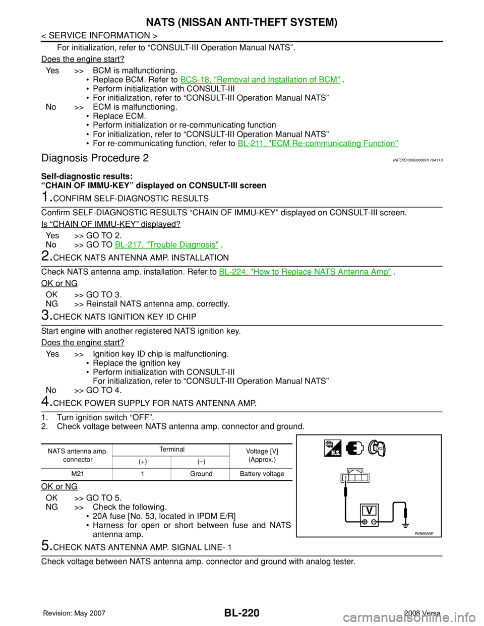
1. Turn ignition switch “OFF”.
2. Check voltage between NATS antenna amp. connector and ground.
OK or NG
OK >> GO TO 5.
NG >> Check the following.
• 20A fuse [No. 53, located in IPDM E/R]
• Harness for open or short between fuse and NATS
antenna amp.
5.CHECK NATS ANTENNA AMP. SIGNAL LINE- 1
Check voltage between NATS antenna amp. connector and ground with analog tester.
NATS antenna amp.
connectorTe r m i n a l
Voltage [V]
(Approx.)
(+) (–)
M21 1 Ground Battery voltage
PIIB6589E
Page 655 of 2771
NATS (NISSAN ANTI-THEFT SYSTEM)
BL-221
< SERVICE INFORMATION >
C
D
E
F
G
H
J
K
L
MA
B
BL
N
O
P
OK or NG
OK >> GO TO 6.
NG >> • Check harness for open or short between NATS antenna amp. and BCM.
NOTE:
If harness is OK, replace BCM, perform initialization with CONSULT-III. For initialization, refer to
“CONSULT-III Operation Manual NATS”.
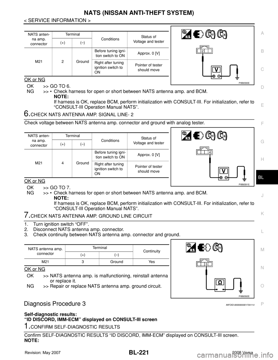
6.CHECK NATS ANTENNA AMP. SIGNAL LINE- 2
Check voltage between NATS antenna amp. connector and ground with analog tester.
OK or NG
OK >> GO TO 7.
NG >> • Check harness for open or short between NATS antenna amp. and BCM.
NOTE:
If harness is OK, replace BCM, perform initialization with CONSULT-III. For initialization, refer to
“CONSULT-III Operation Manual NATS”.
7.CHECK NATS ANTENNA AMP. GROUND LINE CIRCUIT
1. Turn ignition switch “OFF”.
2. Disconnect NATS antenna amp. connector.
3. Check continuity between NATS antenna amp. connector and ground.
OK or NG
OK >> NATS antenna amp. is malfunctioning, reinstall antenna
or replace it.
NG >> Repair or replace NATS antenna amp. ground circuit.
Diagnosis Procedure 3INFOID:0000000001704114
Self-diagnostic results:
“ID DISCORD, IMM-ECM” displayed on CONSULT-III screen
1.CONFIRM SELF-DIAGNOSTIC RESULTS
Confirm SELF-DIAGNOSTIC RESULTS “ID DISCORD, IMM-ECM” displayed on CONSULT-III screen.
NOTE:
NATS anten-
na amp.
connectorTe r m i n a l
ConditionsStatus of
Voltage and tester
(+) (–)
M21 2 GroundBefore tuning igni-
tion switch to ONApprox. 0 [V]
Right after tuning
ignition switch to
ONPointer of tester
should move
PIIB6590E
NATS anten-
na amp.
connectorTe r m i n a l
ConditionsStatus of
Voltage and tester
(+) (–)
M21 4 GroundBefore tuning igni-
tion switch to ONApprox. 0 [V]
Right after tuning
ignition switch to
ONPointer of tester
should move
PIIB6591E
NATS antenna amp.
connectorTe r m i n a l
Continuity
(+) (–)
M21 3 Ground Yes
PIIB6592E
Page 656 of 2771
BL-222
< SERVICE INFORMATION >
NATS (NISSAN ANTI-THEFT SYSTEM)
“ID DISCORD IMM-ECM”:
Registered ID of BCM is in discord with that of ECM.
Is
“ID DISCORD IMM-ECM” displayed?
Ye s > > G O T O 2 .
No >> GO TO BL-217, "
Trouble Diagnosis" .
2.PERFORM INITIALIZATION WITH CONSULT-III
Perform initialization with CONSULT-III. Re-register all NATS ignition key IDs.
For initialization, refer to “CONSULT-III Operation Manual NATS”.
NOTE:
If the initialization is not completed or malfunctions, CONSULT-III shows message on the screen.
Can the system be initialized?
Yes >> • Start engine. (END)
• (System initialization had not been completed.)
No >> ECM is malfunctioning.
• Replace ECM.
• Perform initialization with CONSULT-III
For initialization, refer to “CONSULT-III Operation Manual NATS”
Diagnosis Procedure 4INFOID:0000000001704115
“COMBINATION METER (SECURITY) DOES NOT LIGHT UP”
1.CHECK FUSE
Check 10A fuse [No.13, located in the fuse block (J/B)]
OK or NG
OK >> GO TO 2.
NG >> Replace fuse.
2.CHECK COMBINATION METER (SECURITY)
1. Install 10A fuse.
2. Start engine and turn ignition switch OFF.
3. Check if the combination meter (security) lights up.
OK or NG
OK >> INSPECTION END.
NG >> GO TO 3.
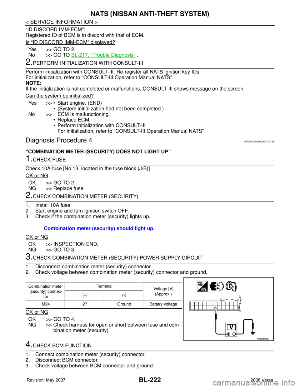
3.CHECK COMBINATION METER (SECURITY) POWER SUPPLY CIRCUIT
1. Disconnect combination meter (security) connector.
2. Check voltage between combination meter (security) connector and ground.
OK or NG
OK >> GO TO 4.
NG >> Check harness for open or short between fuse and com-
bination meter (security).
4.CHECK BCM FUNCTION
1. Connect combination meter (security) connector.
2. Disconnect BCM connector.
3. Check voltage between BCM connector and ground. Combination meter (security) should light up.
Combination meter
(security) connec-
torTe r m i n a l
Voltage [V]
(Approx.)
(+) (-)
M24 27 Ground Battery voltage
PIIB6593E