2008 NISSAN TIIDA fuse
[x] Cancel search: fusePage 530 of 2771
BL-96
< SERVICE INFORMATION >
INTELLIGENT KEY SYSTEM
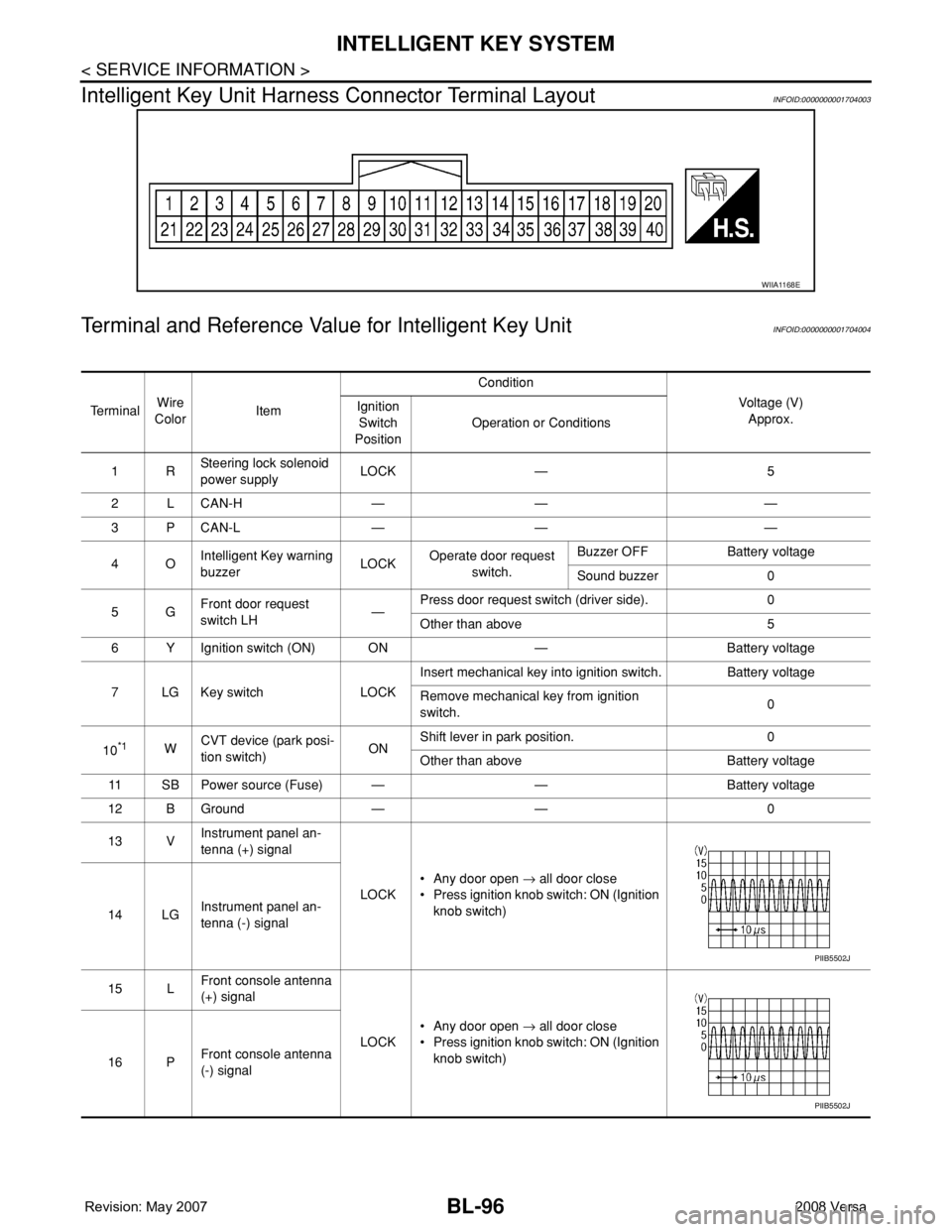
Intelligent Key Unit Harness Connector Terminal Layout
INFOID:0000000001704003
Terminal and Reference Value for Intelligent Key UnitINFOID:0000000001704004
WIIA1168E
Te r m i n a lWire
ColorItemCondition
Voltage (V)
Approx. Ignition
Switch
PositionOperation or Conditions
1RSteering lock solenoid
power supplyLOCK — 5
2 L CAN-H — — —
3 P CAN-L — — —
4OIntelligent Key warning
buzzerLOCKOperate door request
switch.Buzzer OFF Battery voltage
Sound buzzer 0
5GFront door request
switch LH—Press door request switch (driver side). 0
Other than above 5
6 Y Ignition switch (ON) ON — Battery voltage
7 LG Key switch LOCKInsert mechanical key into ignition switch. Battery voltage
Remove mechanical key from ignition
switch.0
10
*1WCVT device (park posi-
tion switch)ONShift lever in park position. 0
Other than above Battery voltage
11 SB Power source (Fuse) — — Battery voltage
12 B Ground — — 0
13 VInstrument panel an-
tenna (+) signal
LOCK• Any door open → all door close
• Press ignition knob switch: ON (Ignition
knob switch)
14 LGInstrument panel an-
tenna (-) signal
15 LFront console antenna
(+) signal
LOCK• Any door open → all door close
• Press ignition knob switch: ON (Ignition
knob switch)
16 PFront console antenna
(-) signal
PIIB5502J
PIIB5502J
Page 546 of 2771
BL-112
< SERVICE INFORMATION >
INTELLIGENT KEY SYSTEM
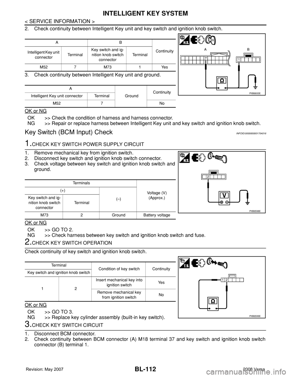
2. Check continuity between Intelligent Key unit and key switch and ignition knob switch.
3. Check continuity between Intelligent Key unit and ground.
OK or NG
OK >> Check the condition of harness and harness connector.
NG >> Repair or replace harness between Intelligent Key unit and key switch and ignition knob switch.
Key Switch (BCM Input) CheckINFOID:0000000001704016
1.CHECK KEY SWITCH POWER SUPPLY CIRCUIT
1. Remove mechanical key from ignition switch.
2. Disconnect key switch and ignition knob switch connector.
3. Check voltage between key switch and ignition knob switch and
ground.
OK or NG
OK >> GO TO 2.
NG >> Check harness between key switch and ignition knob switch and fuse.
2.CHECK KEY SWITCH OPERATION
Check continuity of key switch and ignition knob switch.
OK or NG
OK >> GO TO 3.
NG >> Replace key cylinder assembly (built-in key switch).
3.CHECK KEY SWITCH CIRCUIT
1. Disconnect BCM connector.
2. Check continuity between BCM connector (A) M18 terminal 37 and key switch and ignition knob switch
connector (B) terminal 1.
AB
Continuity
Intelligent Key unit
connectorTe r m i n a lKey switch and ig-
nition knob switch
connectorTe r m i n a l
M52 7 M73 1 Yes
A
GroundContinuity
Intelligent Key unit connector Terminal
M52 7 No
PIIB6600E
Te r m i n a l s
Voltage (V)
(Approx.) (+)
(–) Key switch and ig-
nition knob switch
connectorTe r m i n a l
M73 2 Ground Battery voltage
PIIB6598E
Te r m i n a l
Condition of key switch Continuity
Key switch and ignition knob switch
12Insert mechanical key into
ignition switchYe s
Remove mechanical key
from ignition switchNo
PIIB6599E
Page 568 of 2771
BL-134
< SERVICE INFORMATION >
INTELLIGENT KEY SYSTEM
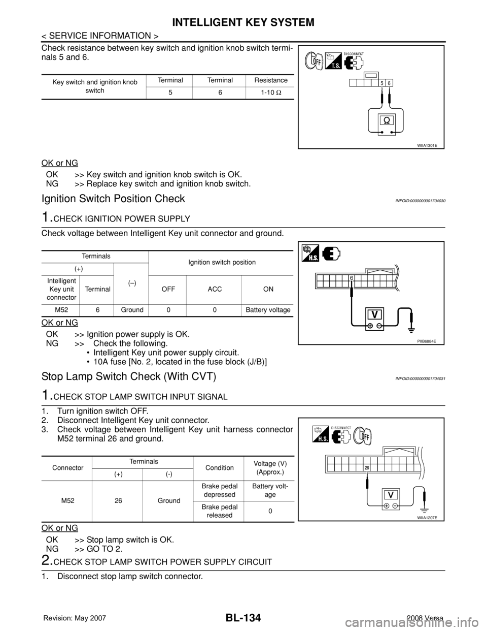
Check resistance between key switch and ignition knob switch termi-
nals 5 and 6.
OK or NG
OK >> Key switch and ignition knob switch is OK.
NG >> Replace key switch and ignition knob switch.
Ignition Switch Position CheckINFOID:0000000001704030
1.CHECK IGNITION POWER SUPPLY
Check voltage between Intelligent Key unit connector and ground.
OK or NG
OK >> Ignition power supply is OK.
NG >> Check the following.
• Intelligent Key unit power supply circuit.
• 10A fuse [No. 2, located in the fuse block (J/B)]
Stop Lamp Switch Check (With CVT)INFOID:0000000001704031
1.CHECK STOP LAMP SWITCH INPUT SIGNAL
1. Turn ignition switch OFF.
2. Disconnect Intelligent Key unit connector.
3. Check voltage between Intelligent Key unit harness connector
M52 terminal 26 and ground.
OK or NG
OK >> Stop lamp switch is OK.
NG >> GO TO 2.
2.CHECK STOP LAMP SWITCH POWER SUPPLY CIRCUIT
1. Disconnect stop lamp switch connector.
Key switch and ignition knob
switchTerminal Terminal Resistance
561-10 Ω
WIIA1301E
Te r m i n a l s
Ignition switch position
(+)
(–) Intelligent
Key unit
connectorTerminal OFF ACC ON
M52 6 Ground 0 0 Battery voltage
PIIB6884E
ConnectorTe r m i n a l s
ConditionVoltage (V)
(Approx.)
(+) (-)
M52 26 GroundBrake pedal
depressedBattery volt-
age
Brake pedal
released0
WIIA1207E
Page 569 of 2771
INTELLIGENT KEY SYSTEM
BL-135
< SERVICE INFORMATION >
C
D
E
F
G
H
J
K
L
MA
B
BL
N
O
P
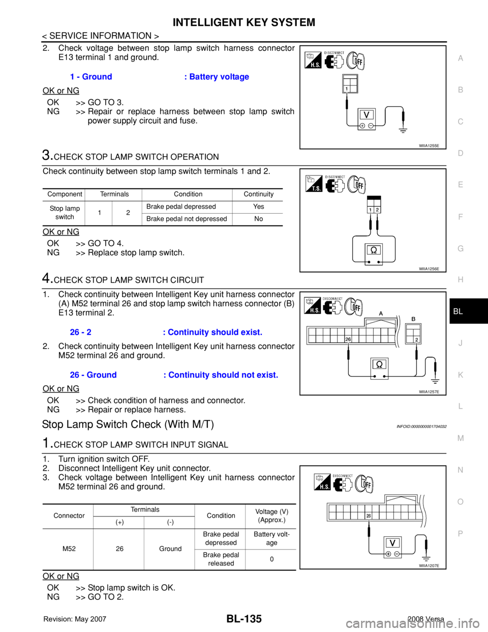
2. Check voltage between stop lamp switch harness connector
E13 terminal 1 and ground.
OK or NG
OK >> GO TO 3.
NG >> Repair or replace harness between stop lamp switch
power supply circuit and fuse.
3.CHECK STOP LAMP SWITCH OPERATION
Check continuity between stop lamp switch terminals 1 and 2.
OK or NG
OK >> GO TO 4.
NG >> Replace stop lamp switch.
4.CHECK STOP LAMP SWITCH CIRCUIT
1. Check continuity between Intelligent Key unit harness connector
(A) M52 terminal 26 and stop lamp switch harness connector (B)
E13 terminal 2.
2. Check continuity between Intelligent Key unit harness connector
M52 terminal 26 and ground.
OK or NG
OK >> Check condition of harness and connector.
NG >> Repair or replace harness.
Stop Lamp Switch Check (With M/T)INFOID:0000000001704032
1.CHECK STOP LAMP SWITCH INPUT SIGNAL
1. Turn ignition switch OFF.
2. Disconnect Intelligent Key unit connector.
3. Check voltage between Intelligent Key unit harness connector
M52 terminal 26 and ground.
OK or NG
OK >> Stop lamp switch is OK.
NG >> GO TO 2.1 - Ground : Battery voltage
WIIA1255E
Component Terminals Condition Continuity
Stop lamp
switch12Brake pedal depressed Yes
Brake pedal not depressed No
WIIA1256E
26 - 2 : Continuity should exist.
26 - Ground : Continuity should not exist.
WIIA1257E
ConnectorTe r m i n a l s
ConditionVoltage (V)
(Approx.)
(+) (-)
M52 26 GroundBrake pedal
depressedBattery volt-
age
Brake pedal
released0
WIIA1207E
Page 570 of 2771
BL-136
< SERVICE INFORMATION >
INTELLIGENT KEY SYSTEM
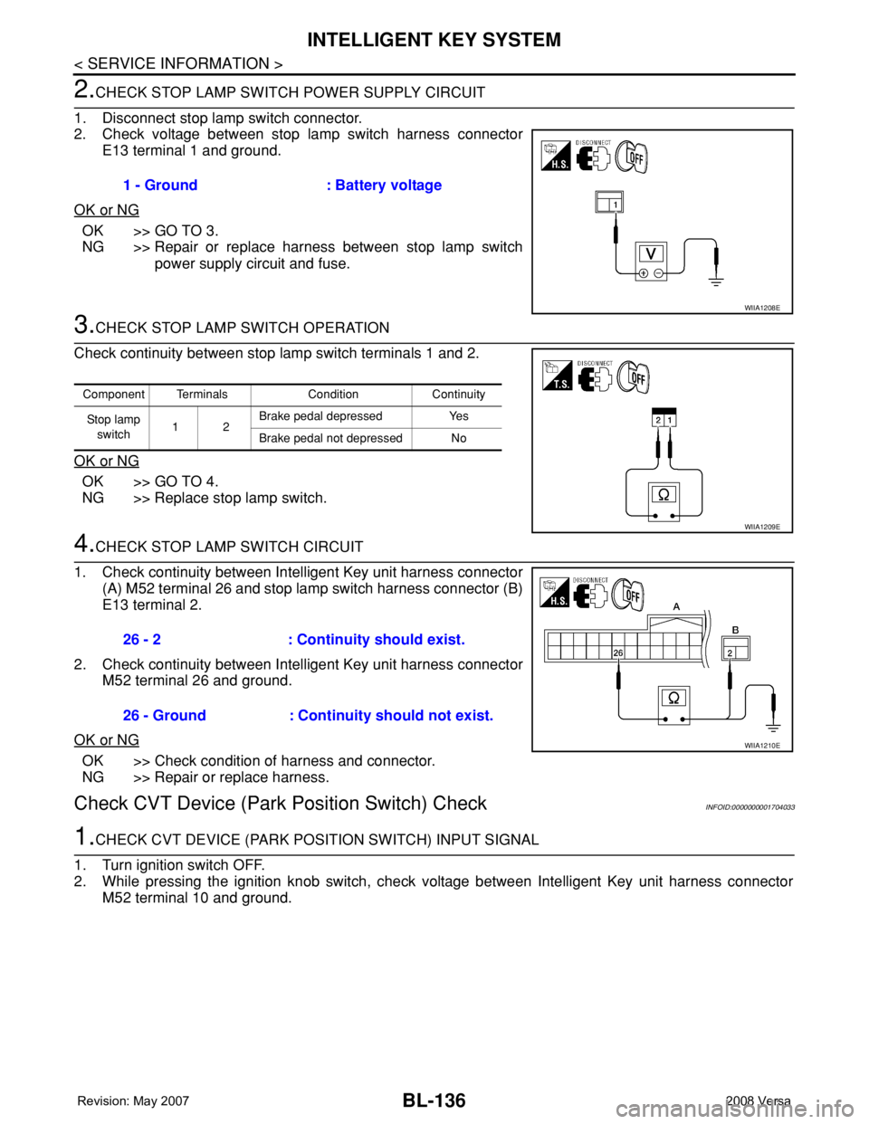
2.CHECK STOP LAMP SWITCH POWER SUPPLY CIRCUIT
1. Disconnect stop lamp switch connector.
2. Check voltage between stop lamp switch harness connector
E13 terminal 1 and ground.
OK or NG
OK >> GO TO 3.
NG >> Repair or replace harness between stop lamp switch
power supply circuit and fuse.
3.CHECK STOP LAMP SWITCH OPERATION
Check continuity between stop lamp switch terminals 1 and 2.
OK or NG
OK >> GO TO 4.
NG >> Replace stop lamp switch.
4.CHECK STOP LAMP SWITCH CIRCUIT
1. Check continuity between Intelligent Key unit harness connector
(A) M52 terminal 26 and stop lamp switch harness connector (B)
E13 terminal 2.
2. Check continuity between Intelligent Key unit harness connector
M52 terminal 26 and ground.
OK or NG
OK >> Check condition of harness and connector.
NG >> Repair or replace harness.
Check CVT Device (Park Position Switch) CheckINFOID:0000000001704033
1.CHECK CVT DEVICE (PARK POSITION SWITCH) INPUT SIGNAL
1. Turn ignition switch OFF.
2. While pressing the ignition knob switch, check voltage between Intelligent Key unit harness connector
M52 terminal 10 and ground.1 - Ground : Battery voltage
WIIA1208E
Component Terminals Condition Continuity
St op la mp
switch12Brake pedal depressed Yes
Brake pedal not depressed No
WIIA1209E
26 - 2 : Continuity should exist.
26 - Ground : Continuity should not exist.
WIIA1210E
Page 590 of 2771
BL-156
< SERVICE INFORMATION >
BACK DOOR LOCK
BACK DOOR LOCK
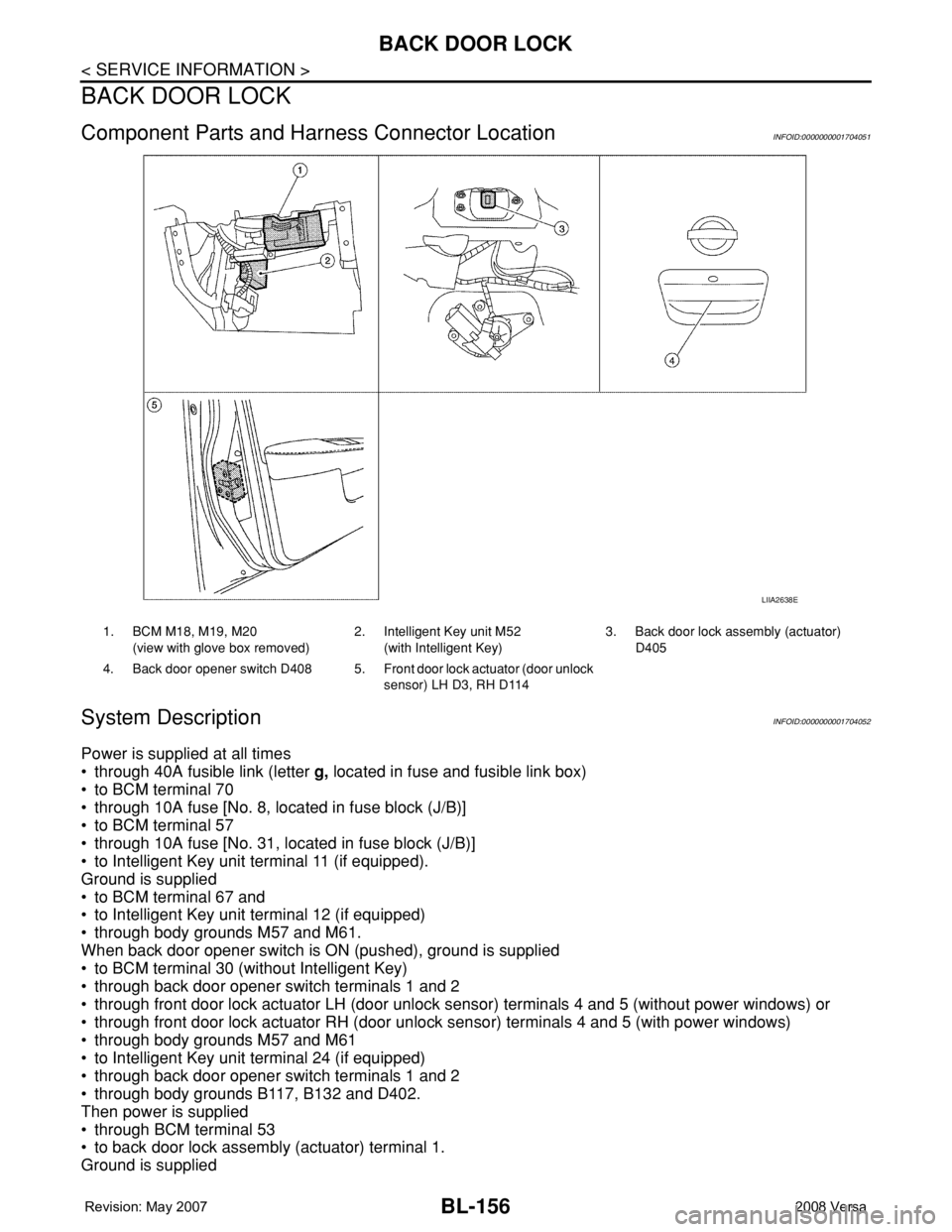
Component Parts and Harness Connector LocationINFOID:0000000001704051
System DescriptionINFOID:0000000001704052
Power is supplied at all times
• through 40A fusible link (letter g, located in fuse and fusible link box)
• to BCM terminal 70
• through 10A fuse [No. 8, located in fuse block (J/B)]
• to BCM terminal 57
• through 10A fuse [No. 31, located in fuse block (J/B)]
• to Intelligent Key unit terminal 11 (if equipped).
Ground is supplied
• to BCM terminal 67 and
• to Intelligent Key unit terminal 12 (if equipped)
• through body grounds M57 and M61.
When back door opener switch is ON (pushed), ground is supplied
• to BCM terminal 30 (without Intelligent Key)
• through back door opener switch terminals 1 and 2
• through front door lock actuator LH (door unlock sensor) terminals 4 and 5 (without power windows) or
• through front door lock actuator RH (door unlock sensor) terminals 4 and 5 (with power windows)
• through body grounds M57 and M61
• to Intelligent Key unit terminal 24 (if equipped)
• through back door opener switch terminals 1 and 2
• through body grounds B117, B132 and D402.
Then power is supplied
• through BCM terminal 53
• to back door lock assembly (actuator) terminal 1.
Ground is supplied
LIIA2638E
1. BCM M18, M19, M20
(view with glove box removed)2. Intelligent Key unit M52
(with Intelligent Key)3. Back door lock assembly (actuator)
D405
4. Back door opener switch D408 5. Front door lock actuator (door unlock
sensor) LH D3, RH D114
Page 607 of 2771
TRUNK LID OPENER
BL-173
< SERVICE INFORMATION >
C
D
E
F
G
H
J
K
L
MA
B
BL
N
O
P
TRUNK LID OPENER
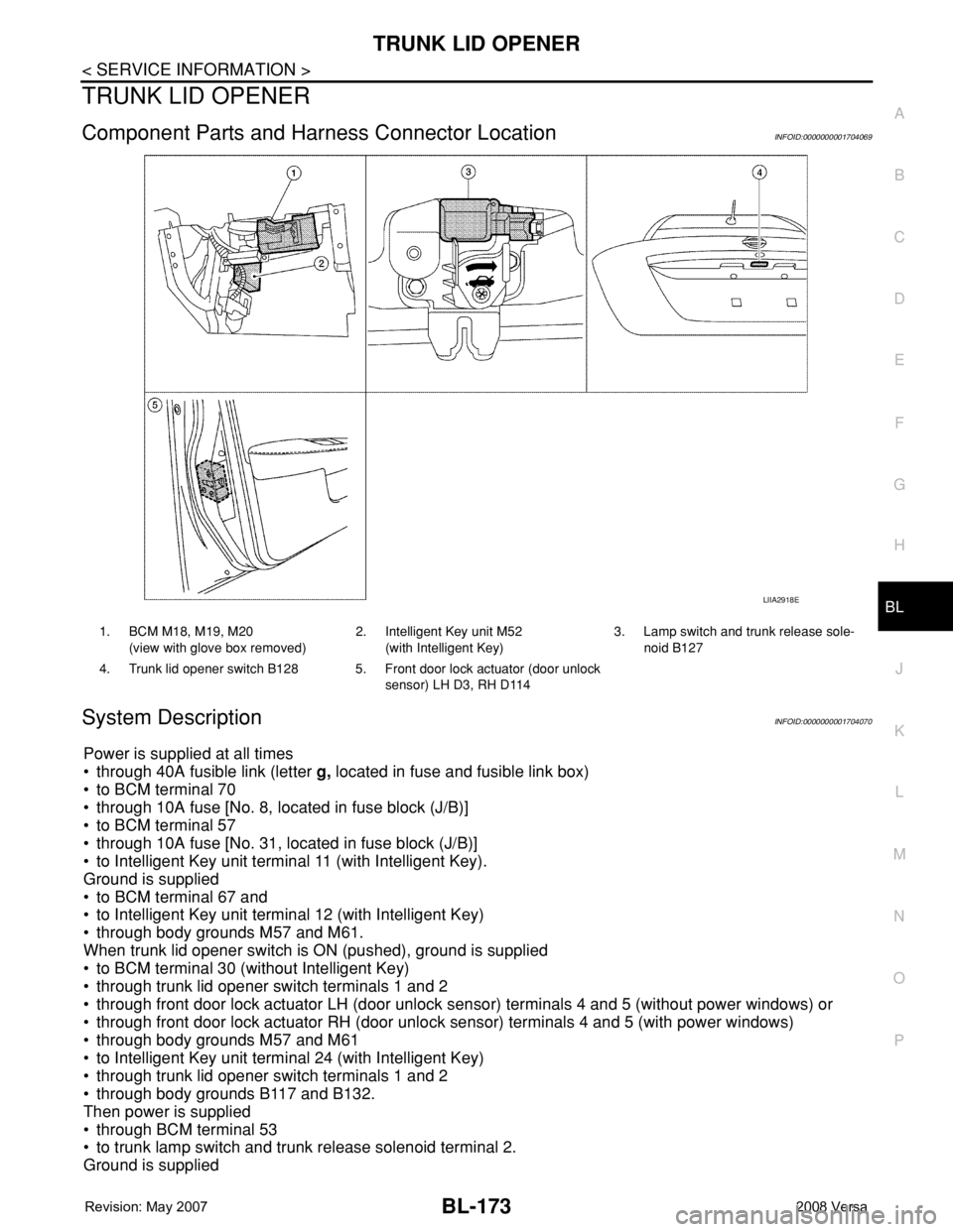
Component Parts and Harness Connector LocationINFOID:0000000001704069
System DescriptionINFOID:0000000001704070
Power is supplied at all times
• through 40A fusible link (letter g, located in fuse and fusible link box)
• to BCM terminal 70
• through 10A fuse [No. 8, located in fuse block (J/B)]
• to BCM terminal 57
• through 10A fuse [No. 31, located in fuse block (J/B)]
• to Intelligent Key unit terminal 11 (with Intelligent Key).
Ground is supplied
• to BCM terminal 67 and
• to Intelligent Key unit terminal 12 (with Intelligent Key)
• through body grounds M57 and M61.
When trunk lid opener switch is ON (pushed), ground is supplied
• to BCM terminal 30 (without Intelligent Key)
• through trunk lid opener switch terminals 1 and 2
• through front door lock actuator LH (door unlock sensor) terminals 4 and 5 (without power windows) or
• through front door lock actuator RH (door unlock sensor) terminals 4 and 5 (with power windows)
• through body grounds M57 and M61
• to Intelligent Key unit terminal 24 (with Intelligent Key)
• through trunk lid opener switch terminals 1 and 2
• through body grounds B117 and B132.
Then power is supplied
• through BCM terminal 53
• to trunk lamp switch and trunk release solenoid terminal 2.
Ground is supplied
LIIA2918E
1. BCM M18, M19, M20
(view with glove box removed)2. Intelligent Key unit M52
(with Intelligent Key)3. Lamp switch and trunk release sole-
noid B127
4. Trunk lid opener switch B128 5. Front door lock actuator (door unlock
sensor) LH D3, RH D114
Page 622 of 2771
BL-188
< SERVICE INFORMATION >
VEHICLE SECURITY (THEFT WARNING) SYSTEM
System Description
INFOID:0000000001704084
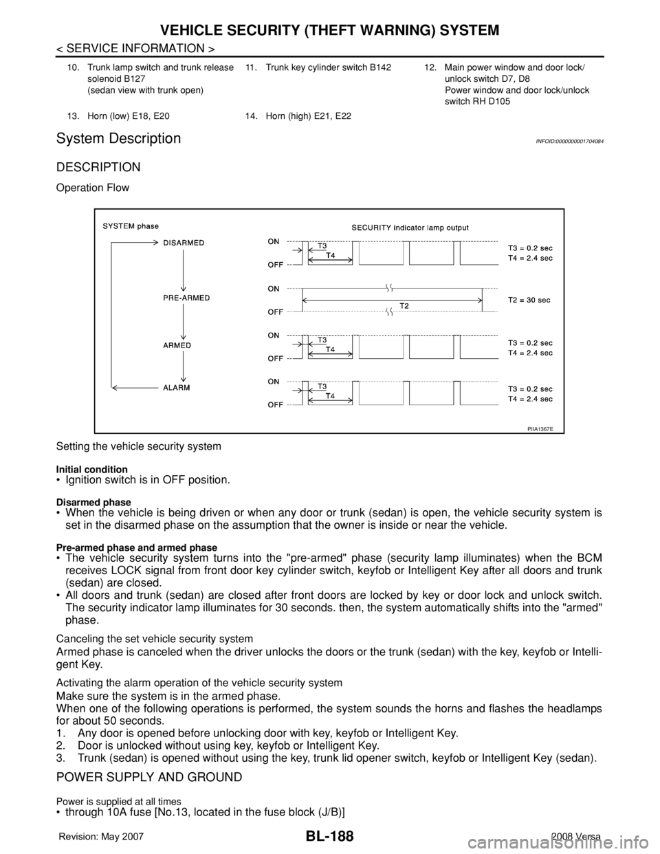
DESCRIPTION
Operation Flow
Setting the vehicle security system
Initial condition• Ignition switch is in OFF position.
Disarmed phase• When the vehicle is being driven or when any door or trunk (sedan) is open, the vehicle security system is
set in the disarmed phase on the assumption that the owner is inside or near the vehicle.
Pre-armed phase and armed phase• The vehicle security system turns into the "pre-armed" phase (security lamp illuminates) when the BCM
receives LOCK signal from front door key cylinder switch, keyfob or Intelligent Key after all doors and trunk
(sedan) are closed.
• All doors and trunk (sedan) are closed after front doors are locked by key or door lock and unlock switch.
The security indicator lamp illuminates for 30 seconds. then, the system automatically shifts into the "armed"
phase.
Canceling the set vehicle security system
Armed phase is canceled when the driver unlocks the doors or the trunk (sedan) with the key, keyfob or Intelli-
gent Key.
Activating the alarm operation of the vehicle security system
Make sure the system is in the armed phase.
When one of the following operations is performed, the system sounds the horns and flashes the headlamps
for about 50 seconds.
1. Any door is opened before unlocking door with key, keyfob or Intelligent Key.
2. Door is unlocked without using key, keyfob or Intelligent Key.
3. Trunk (sedan) is opened without using the key, trunk lid opener switch, keyfob or Intelligent Key (sedan).
POWER SUPPLY AND GROUND
Power is supplied at all times• through 10A fuse [No.13, located in the fuse block (J/B)]
10. Trunk lamp switch and trunk release
solenoid B127
(sedan view with trunk open)11. Trunk key cylinder switch B142 12. Main power window and door lock/
unlock switch D7, D8
Power window and door lock/unlock
switch RH D105
13. Horn (low) E18, E20 14. Horn (high) E21, E22
PIIA1367E