2008 NISSAN TIIDA connector d2
[x] Cancel search: connector d2Page 847 of 2771
CVT-8
< SERVICE INFORMATION >
PRECAUTIONS
• Be sure to turn the ignition switch OFF and disconnect the battery cable from the negative terminal
before any repair or inspection work. The open/short circuit of related switches, sensors, solenoid
valves, etc. will cause the MIL to light up.
• Be sure to connect and lock the connectors securely after work. A loose (unlocked) connector will
cause the MIL to light up due to an open circuit. (Be sure the connector is free from water, grease,
dirt, bent terminals, etc.)
• Be sure to route and secure the harnesses properly after work. Interference of the harness with a
bracket, etc. may cause the MIL to light up due to a short circuit.
• Be sure to connect rubber tubes properly after work. A misconnected or disconnected rubber tube
may cause the MIL to light up due to a malfunction of the EVAP system or fuel injection system, etc.
• Be sure to erase the unnecessary malfunction information (repairs completed) from the TCM and
ECM before returning the vehicle to the customer.
Service After Replacing TCM and Transaxle AssemblyINFOID:0000000001703427
SERVICE AFTER REPLACING TCM AND TRANSAXLE ASSEMBLY
Perform the applicable service in the following sheet when replacing TCM or transaxle assembly
CAUTION:
• Do not start the engine until the service is completed.
• “A/T C/U POWER SUPPLY [P1701]” may be indicated soon after replacing TCM or transaxle assem-
bly (after erasing the memory at the pattern B). Restart the self-diagnosis after erasing the self-diag-
nosis result. Check that no error is detected.
NOTE:
Old unit means that the unit has been already used for another vehicle.
PATTERN A
1. Shift the selector lever to “P” position after replacing TCM. Turn the ignition switch ON.
2. Check that the shift position indicator in the combination meter turns ON (It indicates approximately 1 or 2
seconds after turning the ignition switch ON.)
• Check the following items if the shift position indicator does not turn ON. Repair or replace the shift posi-
tion indicator if necessary.
- The harness between TCM and ROM ASSY in the transaxle assembly is open or short.
- Cable disconnected, loosen, or bent from the connector housing.
PATTERN B
1. Turn the ignition switch ON after replacing each part.
2. Start engine.
CAUTION:
Do not start the driving.
3. Touch CONSULT-III screen in the order of “START (NISSAN BASED VHCL)”, “TRANSMISSION”, “DATA
MONITOR”, and “MAIN SIGNALS”.
4. Warm up the transaxle assembly until “ATFTEMPCOUNT” indicates 47 [approximately 20°C (68°F)] or
more. Turn the ignition switch OFF.
5. Turn the ignition switch ON.
CAUTION:
Do not start engine.
6. Select “SELF-DIAG RESULTS”.
7. Shift the selector lever to “R” position.
8. Depress slightly the accelerator pedal (Pedal angle: 2/8) while depressing the brake pedal.
9. Perform “ERASE”.
TCM CVT assemblyService pattern
Replace the new unit. Do not replace the unit. "PATTERN A"
Do not replace the unit. Replace the new or old unit.
"PATTERN B"
Replace the old unit.Do not replace the unit.
Replace the new or old unit.
Replace the new unit. Replace the new or old unit. "PATTERN C"
Page 848 of 2771
PRECAUTIONS
CVT-9
< SERVICE INFORMATION >
D
E
F
G
H
I
J
K
L
MA
B
CVT
N
O
P
10. Shift the selector lever to “R” position after replacing TCM. Turn the ignition switch OFF.
11. Wait approximately 10 minutes after turning the ignition switch OFF.
12. Turn the ignition switch ON while shifting the selector lever to “R” position.
CAUTION:
Do not start engine.
13. Select “CALIBRATION DATA”.
14. Check that the value on “CALIBRATION DATA” is same as the data after erasing "Calibration Data".
• Restart the procedure from step 3 if the values are not same.
15. Shift the selector lever to “P” position.
16. Check that the shift position indicator in the combination meter turns ON (It indicates approximately 1 or 2
seconds after shifting the selector lever to “P” position.)
• Check the following items if the shift position indicator does not turn ON. Repair or replace the shift posi-
tion indicator if necessary.
- The harness between TCM and ROM ASSY in the transaxle assembly is open or short.
- Cable disconnected, loosen, or bent from the connector housing.
- Power supply and ground of TCM. Refer to CVT-121
.
PATTERN C
1. Replace the transaxle assembly first, and then replace TCM.
2. Perform the service of “PATTERN A”.
(Perform the service of “Pattern B” if TCM is replaced first.)
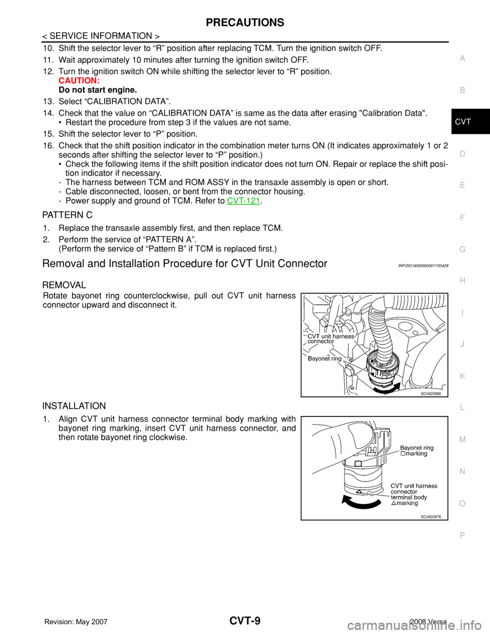
Removal and Installation Procedure for CVT Unit ConnectorINFOID:0000000001703428
REMOVAL
Rotate bayonet ring counterclockwise, pull out CVT unit harness
connector upward and disconnect it.
INSTALLATION
1. Align CVT unit harness connector terminal body marking with
bayonet ring marking, insert CVT unit harness connector, and
then rotate bayonet ring clockwise.
SCIA2096E
SCIA2097E
Page 849 of 2771
CVT-10
< SERVICE INFORMATION >
PRECAUTIONS
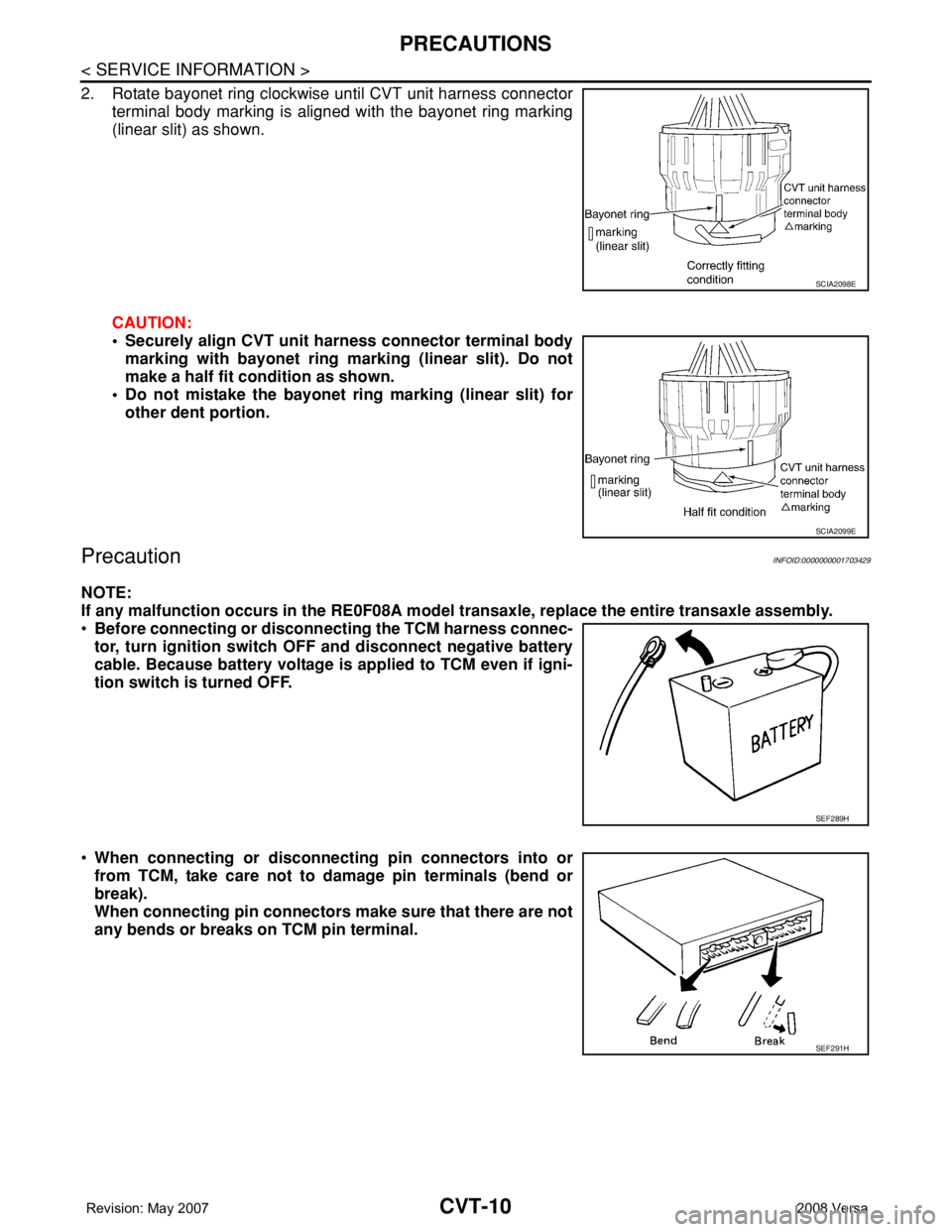
2. Rotate bayonet ring clockwise until CVT unit harness connector
terminal body marking is aligned with the bayonet ring marking
(linear slit) as shown.
CAUTION:
• Securely align CVT unit harness connector terminal body
marking with bayonet ring marking (linear slit). Do not
make a half fit condition as shown.
• Do not mistake the bayonet ring marking (linear slit) for
other dent portion.
PrecautionINFOID:0000000001703429
NOTE:
If any malfunction occurs in the RE0F08A model transaxle, replace the entire transaxle assembly.
•Before connecting or disconnecting the TCM harness connec-
tor, turn ignition switch OFF and disconnect negative battery
cable. Because battery voltage is applied to TCM even if igni-
tion switch is turned OFF.
•When connecting or disconnecting pin connectors into or
from TCM, take care not to damage pin terminals (bend or
break).
When connecting pin connectors make sure that there are not
any bends or breaks on TCM pin terminal.
SCIA2098E
SCIA2099E
SEF289H
SEF291H
Page 850 of 2771
PRECAUTIONS
CVT-11
< SERVICE INFORMATION >
D
E
F
G
H
I
J
K
L
MA
B
CVT
N
O
P
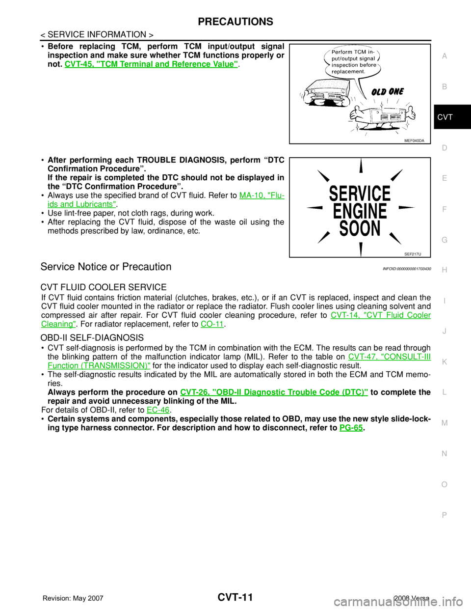
•Before replacing TCM, perform TCM input/output signal
inspection and make sure whether TCM functions properly or
not. CVT-45, "
TCM Terminal and Reference Value".
•After performing each TROUBLE DIAGNOSIS, perform “DTC
Confirmation Procedure”.
If the repair is completed the DTC should not be displayed in
the “DTC Confirmation Procedure”.
• Always use the specified brand of CVT fluid. Refer to MA-10, "
Flu-
ids and Lubricants".
• Use lint-free paper, not cloth rags, during work.
• After replacing the CVT fluid, dispose of the waste oil using the
methods prescribed by law, ordinance, etc.
Service Notice or PrecautionINFOID:0000000001703430
CVT FLUID COOLER SERVICE
If CVT fluid contains friction material (clutches, brakes, etc.), or if an CVT is replaced, inspect and clean the
CVT fluid cooler mounted in the radiator or replace the radiator. Flush cooler lines using cleaning solvent and
compressed air after repair. For CVT fluid cooler cleaning procedure, refer to CVT-14, "
CVT Fluid Cooler
Cleaning". For radiator replacement, refer to CO-11.
OBD-II SELF-DIAGNOSIS
• CVT self-diagnosis is performed by the TCM in combination with the ECM. The results can be read through
the blinking pattern of the malfunction indicator lamp (MIL). Refer to the table on CVT-47, "
CONSULT-III
Function (TRANSMISSION)" for the indicator used to display each self-diagnostic result.
• The self-diagnostic results indicated by the MIL are automatically stored in both the ECM and TCM memo-
ries.
Always perform the procedure on CVT-26, "
OBD-II Diagnostic Trouble Code (DTC)" to complete the
repair and avoid unnecessary blinking of the MIL.
For details of OBD-II, refer to EC-46
.
•Certain systems and components, especially those related to OBD, may use the new style slide-lock-
ing type harness connector. For description and how to disconnect, refer to PG-65
.
MEF040DA
SEF217U
Page 874 of 2771
TROUBLE DIAGNOSIS
CVT-35
< SERVICE INFORMATION >
D
E
F
G
H
I
J
K
L
MA
B
CVT
N
O
P
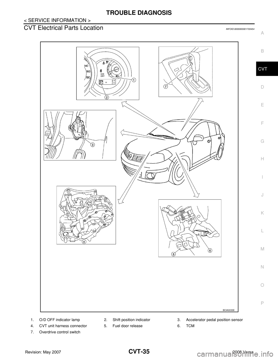
CVT Electrical Parts LocationINFOID:0000000001703454
1. O/D OFF indicator lamp 2. Shift position indicator 3. Accelerator pedal position sensor
4. CVT unit harness connector 5. Fuel door release 6. TCM
7. Overdrive control switch
BCIA0033E
Page 884 of 2771
TROUBLE DIAGNOSIS
CVT-45
< SERVICE INFORMATION >
D
E
F
G
H
I
J
K
L
MA
B
CVT
N
O
P
9.CHECK ENGINE BRAKE FUNCTION — PART 3
1. Move selector lever to “L” position.
2. Check engine brake.
Does engine braking effectively reduce speed in
“L” position?
YES >> 1. Stop the vehicle.
2. Perform self-diagnosis. Refer to CVT-47, "
CONSULT-III Function (TRANSMISSION)" .
NO >> Mark the box of CVT-159, "
Vehicle Does Not Decelerate by Engine Brake" on the CVT-30, "How
to Perform Trouble Diagnosis for Quick and Accurate Repair" . Then continue trouble diagnosis.
Vehicle Speed When Shifting GearsINFOID:0000000001703461
Numerical value data are reference values.
CAUTION:
Lock-up clutch is engaged when vehicle speed is approximately 18 km/h (11 MPH) to 90 km/h (56 MPH).
TCM Terminal and Reference ValueINFOID:0000000001703462
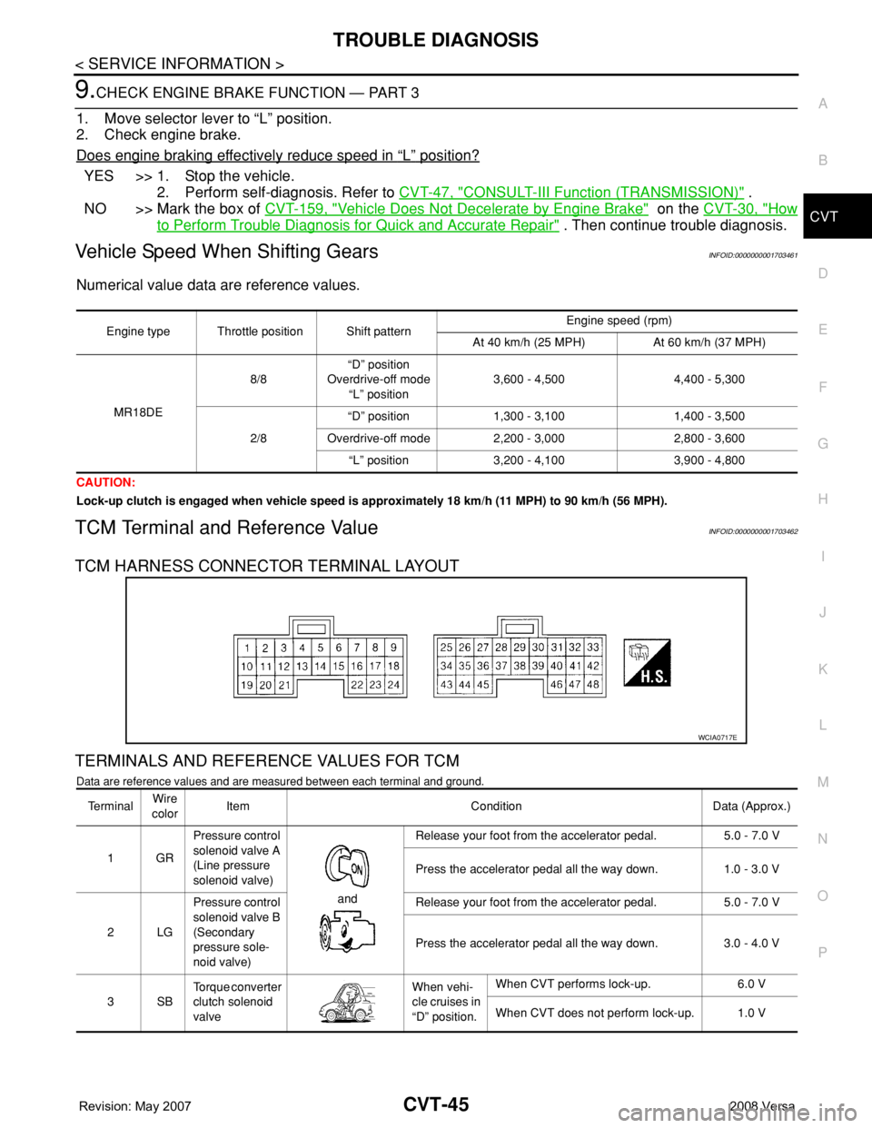
TCM HARNESS CONNECTOR TERMINAL LAYOUT
TERMINALS AND REFERENCE VALUES FOR TCM
Data are reference values and are measured between each terminal and ground.
Engine type Throttle position Shift patternEngine speed (rpm)
At 40 km/h (25 MPH) At 60 km/h (37 MPH)
MR18DE8/8“D” position
Overdrive-off mode
“L” position3,600 - 4,500 4,400 - 5,300
2/8“D” position 1,300 - 3,100 1,400 - 3,500
Overdrive-off mode 2,200 - 3,000 2,800 - 3,600
“L” position 3,200 - 4,100 3,900 - 4,800
WCIA0717E
Te r m i n a lWire
colorItem Condition Data (Approx.)
1GRPressure control
solenoid valve A
(Line pressure
solenoid valve)
and Release your foot from the accelerator pedal. 5.0 - 7.0 V
Press the accelerator pedal all the way down. 1.0 - 3.0 V
2LGPressure control
solenoid valve B
(Secondary
pressure sole-
noid valve) Release your foot from the accelerator pedal. 5.0 - 7.0 V
Press the accelerator pedal all the way down. 3.0 - 4.0 V
3SBTorque converter
clutch solenoid
valveWhen vehi-
cle cruises in
“D” position.When CVT performs lock-up. 6.0 V
When CVT does not perform lock-up. 1.0 V
Page 895 of 2771
CVT-56
< SERVICE INFORMATION >
DTC U1000 CAN COMMUNICATION LINE
DTC U1000 CAN COMMUNICATION LINE
DescriptionINFOID:0000000001703465
CAN (Controller Area Network) is a serial communication line for real time application. It is an on-vehicle mul-
tiplex communication line with high data communication speed and excellent malfunction detection ability.
Many electronic control units are equipped onto a vehicle, and each control unit shares information and links
with other control units during operation (not independent). In CAN communication, control units are con-
nected with 2 communication lines (CAN-H line, CAN-L line) allowing a high rate of information transmission
with less wiring. Each control unit transmits/receives data but selectively reads required data only.
On Board Diagnosis LogicINFOID:0000000001703466
• This is an OBD-II self-diagnostic item.
• Diagnostic trouble code “U1000 CAN COMM CIRCUIT” with CONSULT-III is detected when TCM cannot
communicate to other control units.
Possible CauseINFOID:0000000001703467
Harness or connectors
(CAN communication line is open or shorted.)
DTC Confirmation ProcedureINFOID:0000000001703468
NOTE:
If “DTC Confirmation Procedure” has been previously performed, always turn ignition switch OFF and
wait at least 10 seconds before performing the next test.
After the repair, touch “ERASE” on “SELF-DIAG RESULTS” and then perform the following procedure to con-
firm the malfunction is eliminated.
WITH CONSULT-III
1. Turn ignition switch ON. (Do not start engine.)
2. Select “DATA MONITOR” mode for “TRANSMISSION” with CONSULT-III.
3. Start engine and wait for at least 6 seconds.
4. If DTC is detected, go to CVT-58, "
Diagnosis Procedure" .
WITH GST
Follow the procedure “WITH CONSULT-III”.
Page 898 of 2771
DTC U1010 TRANSMISSION CONTROL MODULE (CAN)
CVT-59
< SERVICE INFORMATION >
D
E
F
G
H
I
J
K
L
MA
B
CVT
N
O
P
DTC U1010 TRANSMISSION CONTROL MODULE (CAN)
DescriptionINFOID:0000000001703471
CAN (Controller Area Network) is a serial communication line for real time application. It is an on-vehicle mul-
tiplex communication line with high data communication speed and excellent malfunction detection ability.
Many electronic control units are equipped onto a vehicle, and each control unit shares information and links
with other control units during operation (not independent). In CAN communication, control units are con-
nected with 2 communication lines (CAN-H line, CAN-L line) allowing a high rate of information transmission
with less wiring. Each control unit transmits/receives data but selectively reads required data only.
On Board Diagnosis LogicINFOID:0000000001703472
• This is an OBD-II self-diagnostic item.
• Diagnostic trouble code “U1010 CONTROL UNIT(CAN)” with CONSULT-III is detected when TCM cannot
communicate to other control units.
Possible CauseINFOID:0000000001703473
Harness or connectors
(CAN communication line is open or shorted.)
DTC Confirmation ProcedureINFOID:0000000001703474
NOTE:
If “DTC Confirmation Procedure” has been previously performed, always turn ignition switch OFF and
wait at least 10 seconds before performing the next test.
After the repair, touch “ERASE” on “SELF-DIAG RESULTS” and then perform the following procedure to con-
firm the malfunction is eliminated.
WITH CONSULT-III
1. Turn ignition switch ON. (Do not start engine.)
2. Select “DATA MONITOR” mode for “TRANSMISSION” with CONSULT-III.
3. Start engine and wait for at least 6 seconds.
4. If DTC is detected, go to CVT-59, "
Diagnosis Procedure".
WITH GST
Follow the procedure “WITH CONSULT-III”.
Diagnosis ProcedureINFOID:0000000001703475
1.CHECK DTC
With CONSULT-III
1. Turn ignition switch ON. (Do not start engine.)
2. Select “SELF-DIAG RESULTS” mode for “TRANSMISSION” with CONSULT-III.
3. Touch “ERASE”.
4. Turn ignition switch OFF and wait for at least 10 seconds.
5. Perform “DTC confirmation procedure”. Refer to CVT-59, "
DTC Confirmation Procedure".
Is any malfunction of the
“U1010 CONTROL UNIT(CAN)” indicated?
YES >> Replace the TCM. Refer to CVT-161, "Removal and Installation".
NO >>INSPECTION END