Page 52 of 2771

AT-40
< SERVICE INFORMATION >
TROUBLE DIAGNOSIS
●: Solenoid ON
×: Solenoid OFF
–: Non-standard condition
Line Pressure Solenoid Valve
If non-standard solenoid signal is sent to TCM, line pressure solenoid valve is turned OFF to achieve maxi-
mum oil pressure.
Torque Converter Clutch Solenoid Valve
If non-standard solenoid signal is sent to TCM, torque converter clutch solenoid valve is turned OFF to release
lock-up.
Overrun Clutch Solenoid Valve
If non-standard solenoid signal is sent to TCM, overrun clutch solenoid valve is turned OFF to engage overrun
clutch. This will result in more effective engine brake during deceleration.
How to Perform Trouble Diagnosis for Quick and Accurate RepairINFOID:0000000001703179
INTRODUCTION
The TCM receives a signal from the vehicle speed sensor, accelera-
tor pedal position sensor or PNP switch and provides shift control or
lock-up control via A/T solenoid valves.
The TCM also communicates with the ECM by means of a signal
sent from sensing elements used with the OBD-related parts of the
A/T system for malfunction-diagnostic purposes. The TCM is capa-
ble of diagnosing malfunctioning parts while the ECM can store mal-
functions in its memory.
Input and output signals must always be correct and stable in the
operation of the A/T system. The A/T system must be in good oper-
ating condition and be free of valve seizure, solenoid valve malfunc-
tion, etc.
It is much more difficult to diagnose a malfunction that occurs intermittently rather than continuously. Most
intermittent malfunctions are caused by poor electric connections or improper wiring. In this case, careful
checking of suspected circuits may help prevent the replacement of good parts.
Shift positionNormalMalfunction in solenoid
valve AMalfunction in solenoid
valve BMalfunction in solenoid
valves A and B
A B Gear A B Gear A B Gear A B Gear
“D” position●●1st –●→×
3rd ●→×–
3rd ––
3rd ×●2nd –●→× ×–––
××3rd – x×–––
●×4th – x●→×–––
“2” position●●1st –●→×●→×–––
×●2nd –●→× ×–––
××3rd – x×–––
“1” position●●1st –●→×●→×–––
×●2nd –●→× ×–––
××3rd – x×–––
SAT631IA
Page 58 of 2771
AT-46
< SERVICE INFORMATION >
TROUBLE DIAGNOSIS
A/T Electrical Parts Location
INFOID:0000000001703180
1. OD OFF indicator lamp 2. Shift position indicator 3. Accelerator pedal position (APP)
sensor
4. Turbine revolution sensor (Power
train revolution sensor)5. PNP switch 6. Terminal body (Terminal cord as-
sembly connector)
BCIA0037E
Page 59 of 2771
TROUBLE DIAGNOSIS
AT-47
< SERVICE INFORMATION >
D
E
F
G
H
I
J
K
L
MA
B
AT
N
O
P
Circuit DiagramINFOID:0000000001703181
7. Revolution sensor 8. Dropping resistor 9. TCM
10. Overdrive control switch
BCWA0647E
Page 65 of 2771
TROUBLE DIAGNOSIS
AT-53
< SERVICE INFORMATION >
D
E
F
G
H
I
J
K
L
MA
B
AT
N
O
P
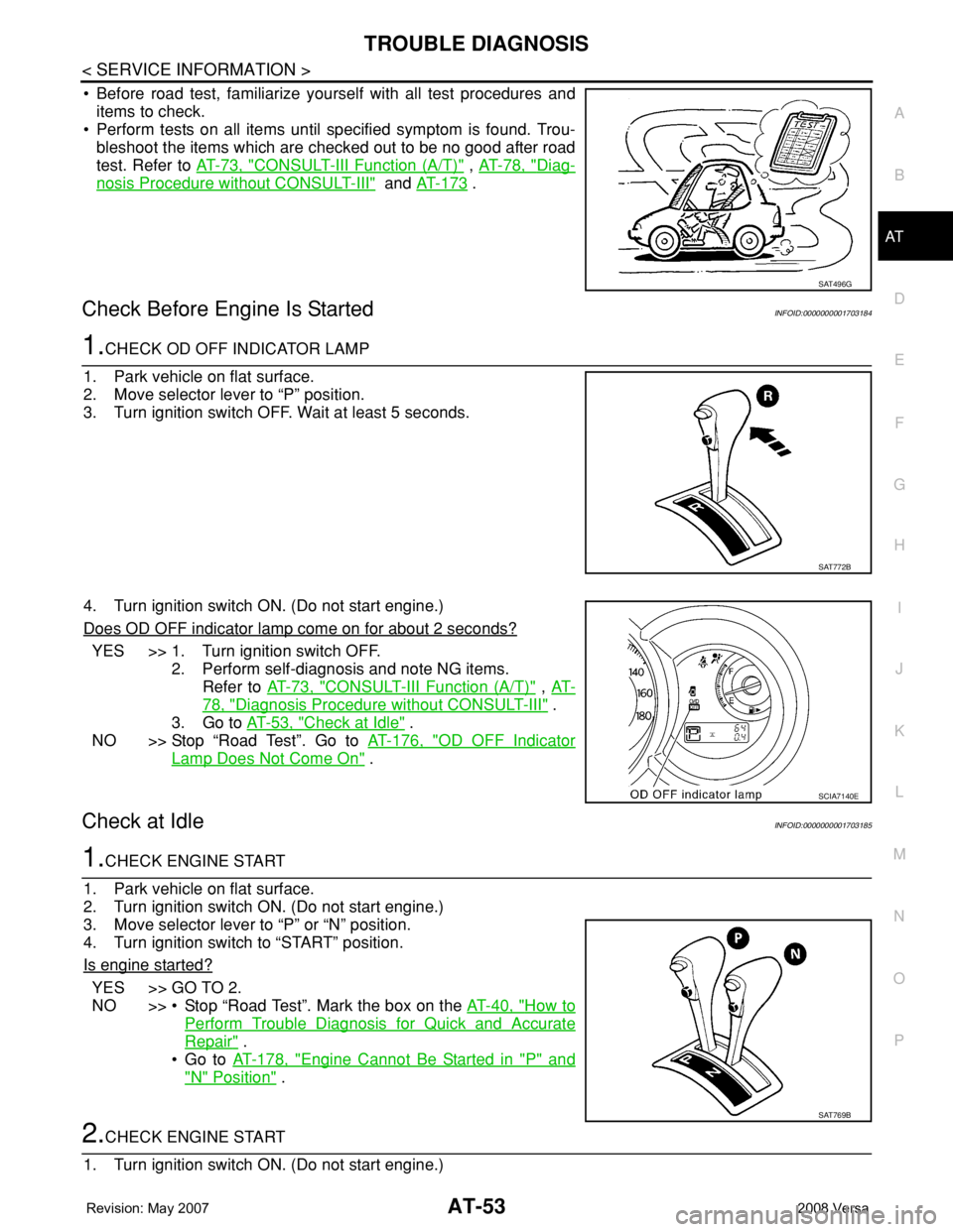
• Before road test, familiarize yourself with all test procedures and
items to check.
• Perform tests on all items until specified symptom is found. Trou-
bleshoot the items which are checked out to be no good after road
test. Refer to AT-73, "
CONSULT-III Function (A/T)" , AT-78, "Diag-
nosis Procedure without CONSULT-III" and AT-173 .
Check Before Engine Is StartedINFOID:0000000001703184
1.CHECK OD OFF INDICATOR LAMP
1. Park vehicle on flat surface.
2. Move selector lever to “P” position.
3. Turn ignition switch OFF. Wait at least 5 seconds.
4. Turn ignition switch ON. (Do not start engine.)
Does OD OFF indicator lamp come on for about 2 seconds?
YES >> 1. Turn ignition switch OFF.
2. Perform self-diagnosis and note NG items.
Refer to AT-73, "
CONSULT-III Function (A/T)" , AT-
78, "Diagnosis Procedure without CONSULT-III" .
3. Go to AT-53, "
Check at Idle" .
NO >> Stop “Road Test”. Go to AT-176, "
OD OFF Indicator
Lamp Does Not Come On" .
Check at IdleINFOID:0000000001703185
1.CHECK ENGINE START
1. Park vehicle on flat surface.
2. Turn ignition switch ON. (Do not start engine.)
3. Move selector lever to “P” or “N” position.
4. Turn ignition switch to “START” position.
Is engine started?
YES >> GO TO 2.
NO >> • Stop “Road Test”. Mark the box on the AT-40, "
How to
Perform Trouble Diagnosis for Quick and Accurate
Repair" .
•Go to AT-178, "
Engine Cannot Be Started in "P" and
"N" Position" .
2.CHECK ENGINE START
1. Turn ignition switch ON. (Do not start engine.)
SAT496G
SAT772B
SCIA7140E
SAT769B
Page 66 of 2771
AT-54
< SERVICE INFORMATION >
TROUBLE DIAGNOSIS
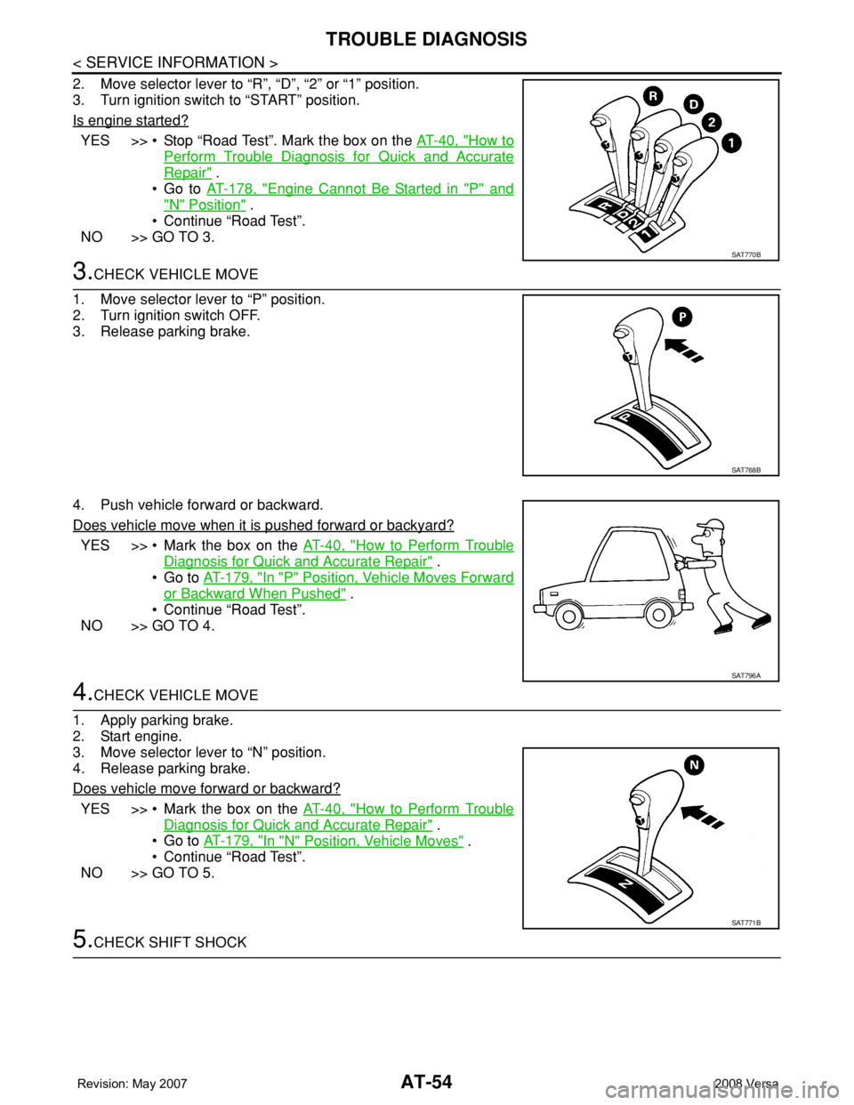
2. Move selector lever to “R”, “D”, “2” or “1” position.
3. Turn ignition switch to “START” position.
Is engine started?
YES >> • Stop “Road Test”. Mark the box on the AT-40, "How to
Perform Trouble Diagnosis for Quick and Accurate
Repair" .
•Go to AT-178, "
Engine Cannot Be Started in "P" and
"N" Position" .
• Continue “Road Test”.
NO >> GO TO 3.
3.CHECK VEHICLE MOVE
1. Move selector lever to “P” position.
2. Turn ignition switch OFF.
3. Release parking brake.
4. Push vehicle forward or backward.
Does vehicle move when it is pushed forward or backyard?
YES >> • Mark the box on the AT-40, "How to Perform Trouble
Diagnosis for Quick and Accurate Repair" .
•Go to AT-179, "
In "P" Position, Vehicle Moves Forward
or Backward When Pushed" .
• Continue “Road Test”.
NO >> GO TO 4.
4.CHECK VEHICLE MOVE
1. Apply parking brake.
2. Start engine.
3. Move selector lever to “N” position.
4. Release parking brake.
Does vehicle move forward or backward?
YES >> • Mark the box on the AT-40, "How to Perform Trouble
Diagnosis for Quick and Accurate Repair" .
•Go to AT-179, "
In "N" Position, Vehicle Moves" .
• Continue “Road Test”.
NO >> GO TO 5.
5.CHECK SHIFT SHOCK
SAT770B
SAT768B
SAT796A
SAT771B
Page 68 of 2771
AT-56
< SERVICE INFORMATION >
TROUBLE DIAGNOSIS
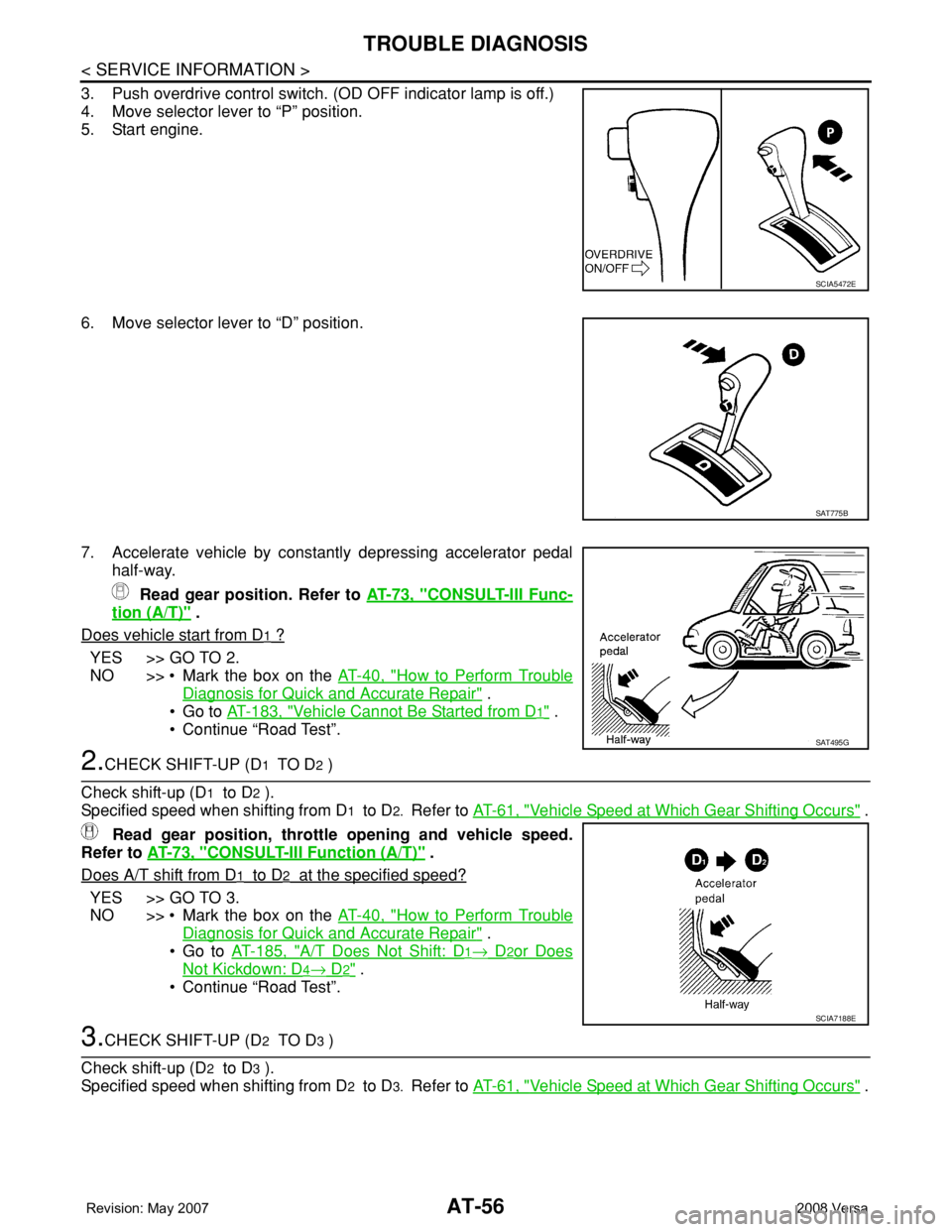
3. Push overdrive control switch. (OD OFF indicator lamp is off.)
4. Move selector lever to “P” position.
5. Start engine.
6. Move selector lever to “D” position.
7. Accelerate vehicle by constantly depressing accelerator pedal
half-way.
Read gear position. Refer to AT-73, "
CONSULT-III Func-
tion (A/T)" .
Does vehicle start from D
1 ?
YES >> GO TO 2.
NO >> • Mark the box on the AT-40, "
How to Perform Trouble
Diagnosis for Quick and Accurate Repair" .
•Go to AT-183, "
Vehicle Cannot Be Started from D1" .
• Continue “Road Test”.
2.CHECK SHIFT-UP (D1 TO D2 )
Check shift-up (D
1 to D2 ).
Specified speed when shifting from D
1 to D2. Refer to AT-61, "Vehicle Speed at Which Gear Shifting Occurs" .
Read gear position, throttle opening and vehicle speed.
Refer to AT-73, "
CONSULT-III Function (A/T)" .
Does A/T shift from D
1 to D2 at the specified speed?
YES >> GO TO 3.
NO >> • Mark the box on the AT-40, "
How to Perform Trouble
Diagnosis for Quick and Accurate Repair" .
•Go to AT-185, "
A/T Does Not Shift: D1→ D2or Does
Not Kickdown: D4→ D2" .
• Continue “Road Test”.
3.CHECK SHIFT-UP (D2 TO D3 )
Check shift-up (D
2 to D3 ).
Specified speed when shifting from D
2 to D3. Refer to AT-61, "Vehicle Speed at Which Gear Shifting Occurs" .
SCIA5472E
SAT775B
SAT495G
SCIA7188E
Page 70 of 2771
AT-58
< SERVICE INFORMATION >
TROUBLE DIAGNOSIS
• Continue “Road Test”.
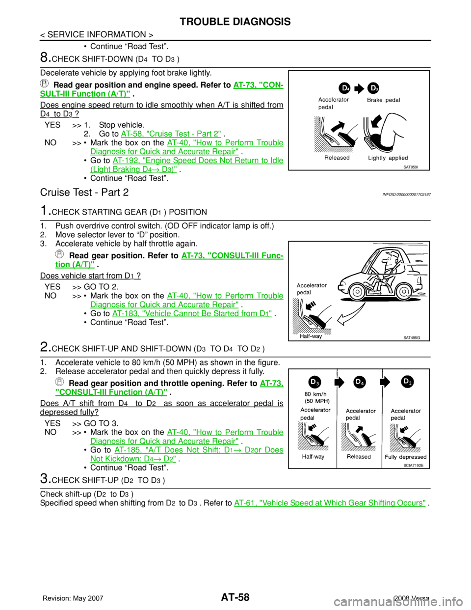
8.CHECK SHIFT-DOWN (D4 TO D3 )
Decelerate vehicle by applying foot brake lightly.
Read gear position and engine speed. Refer to AT-73, "
CON-
SULT-III Function (A/T)" .
Does engine speed return to idle smoothly when A/T is shifted from
D4 to D3 ?
YES >> 1. Stop vehicle.
2. Go to AT-58, "
Cruise Test - Part 2" .
NO >> • Mark the box on the AT-40, "
How to Perform Trouble
Diagnosis for Quick and Accurate Repair" .
•Go to AT-192, "
Engine Speed Does Not Return to Idle
(Light Braking D4→ D3)" .
• Continue “Road Test”.
Cruise Test - Part 2INFOID:0000000001703187
1.CHECK STARTING GEAR (D1 ) POSITION
1. Push overdrive control switch. (OD OFF indicator lamp is off.)
2. Move selector lever to “D” position.
3. Accelerate vehicle by half throttle again.
Read gear position. Refer to AT-73, "
CONSULT-III Func-
tion (A/T)" .
Does vehicle start from D
1 ?
YES >> GO TO 2.
NO >> • Mark the box on the AT-40, "
How to Perform Trouble
Diagnosis for Quick and Accurate Repair" .
•Go to AT-183, "
Vehicle Cannot Be Started from D1" .
• Continue “Road Test”.
2.CHECK SHIFT-UP AND SHIFT-DOWN (D3 TO D4 TO D2 )
1. Accelerate vehicle to 80 km/h (50 MPH) as shown in the figure.
2. Release accelerator pedal and then quickly depress it fully.
Read gear position and throttle opening. Refer to AT-73,
"CONSULT-III Function (A/T)" .
Does A/T shift from D
4 to D2 as soon as accelerator pedal is
depressed fully?
YES >> GO TO 3.
NO >> • Mark the box on the AT-40, "
How to Perform Trouble
Diagnosis for Quick and Accurate Repair" .
•Go to AT-185, "
A/T Does Not Shift: D1→ D2or Does
Not Kickdown: D4→ D2" .
• Continue “Road Test”.
3.CHECK SHIFT-UP (D2 TO D3 )
Check shift-up (D
2 to D3 )
Specified speed when shifting from D
2 to D3 . Refer to AT-61, "Vehicle Speed at Which Gear Shifting Occurs" .
SAT959I
SAT495G
SCIA7192E
Page 71 of 2771
TROUBLE DIAGNOSIS
AT-59
< SERVICE INFORMATION >
D
E
F
G
H
I
J
K
L
MA
B
AT
N
O
P
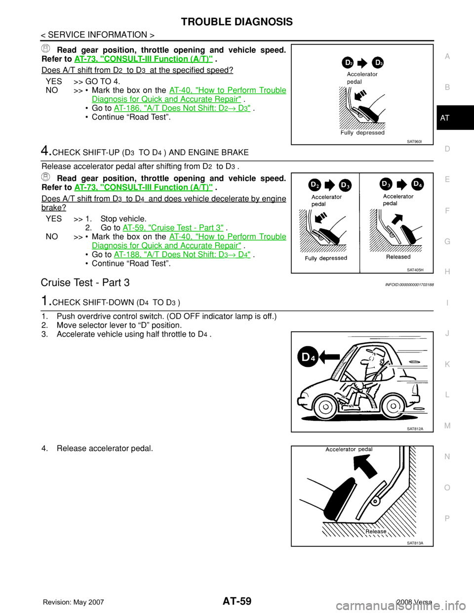
Read gear position, throttle opening and vehicle speed.
Refer to AT-73, "
CONSULT-III Function (A/T)" .
Does A/T shift from D
2 to D3 at the specified speed?
YES >> GO TO 4.
NO >> • Mark the box on the AT-40, "
How to Perform Trouble
Diagnosis for Quick and Accurate Repair" .
•Go to AT-186, "
A/T Does Not Shift: D2→ D3" .
• Continue “Road Test”.
4.CHECK SHIFT-UP (D3 TO D4 ) AND ENGINE BRAKE
Release accelerator pedal after shifting from D
2 to D3 .
Read gear position, throttle opening and vehicle speed.
Refer to AT-73, "
CONSULT-III Function (A/T)" .
Does A/T shift from D
3 to D4 and does vehicle decelerate by engine
brake?
YES >> 1. Stop vehicle.
2. Go to AT-59, "
Cruise Test - Part 3" .
NO >> • Mark the box on the AT-40, "
How to Perform Trouble
Diagnosis for Quick and Accurate Repair" .
•Go to AT-188, "
A/T Does Not Shift: D3→ D4" .
• Continue “Road Test”.
Cruise Test - Part 3INFOID:0000000001703188
1.CHECK SHIFT-DOWN (D4 TO D3 )
1. Push overdrive control switch. (OD OFF indicator lamp is off.)
2. Move selector lever to “D” position.
3. Accelerate vehicle using half throttle to D
4 .
4. Release accelerator pedal.
SAT960I
SAT405H
SAT812A
SAT813A