Page 1166 of 2771
EC-92
< SERVICE INFORMATION >
TROUBLE DIAGNOSIS
1 - 6: The numbers refer to the order of inspection.Cooling Radiator/Hose/Radiator filler cap
55555 55 45CO-11
Thermostat 5CO-17
Water pumpCO-16
Water galleryCO-7
Cooling fan
5CO-14
Coolant level (Low)/Contaminat-
ed coolantCO-8
NVIS (NISSAN Vehicle Immobilizer System-
NATS)11BL-210
SYMPTOM
Reference
page
HARD/NO START/RESTART (EXCP. HA)
ENGINE STALL
HESITATION/SURGING/FLAT SPOT
SPARK KNOCK/DETONATION
LACK OF POWER/POOR ACCELERATION
HIGH IDLE/LOW IDLE
ROUGH IDLE/HUNTING
IDLING VIBRATION
SLOW/NO RETURN TO IDLE
OVERHEATS/WATER TEMPERATURE HIGH
EXCESSIVE FUEL CONSUMPTION
EXCESSIVE OIL CONSUMPTION
BATTERY DEAD (UNDER CHARGE)
Warranty symptom code AA AB AC AD AE AF AG AH AJ AK AL AM HA
Page 1347 of 2771
DTC P0181 FTT SENSOR
EC-273
< SERVICE INFORMATION >
C
D
E
F
G
H
I
J
K
L
MA
EC
N
P O
1. Turn ignition switch OFF.
2. Check harness continuity between “fuel level sensor unit and fuel pump” terminal 5 and combination
meter terminal 24. Refer to Wiring Diagram.
3. Also check harness for short to ground and short to power.
OK or NG
OK >> GO TO 6.
NG >> GO TO 5.
5.DETECT MALFUNCTIONING PART
Check the following.
• Harness connectors B102, M13
• Harness for open or short between “fuel level sensor unit and fuel pump” and ground.
>> Repair open circuit or short to ground or short to power in harness or connectors.
6.CHECK FUEL TANK TEMPERATURE SENSOR
Refer to, EC-273, "
Component Inspection".
OK or NG
OK >> GO TO 7.
NG >> Replace “fuel level sensor unit and fuel pump”.
7.CHECK INTERMITTENT INCIDENT
Perform EC-136
.
>>INSPECTION END
Component InspectionINFOID:0000000001702773
FUEL TANK TEMPERATURE SENSOR
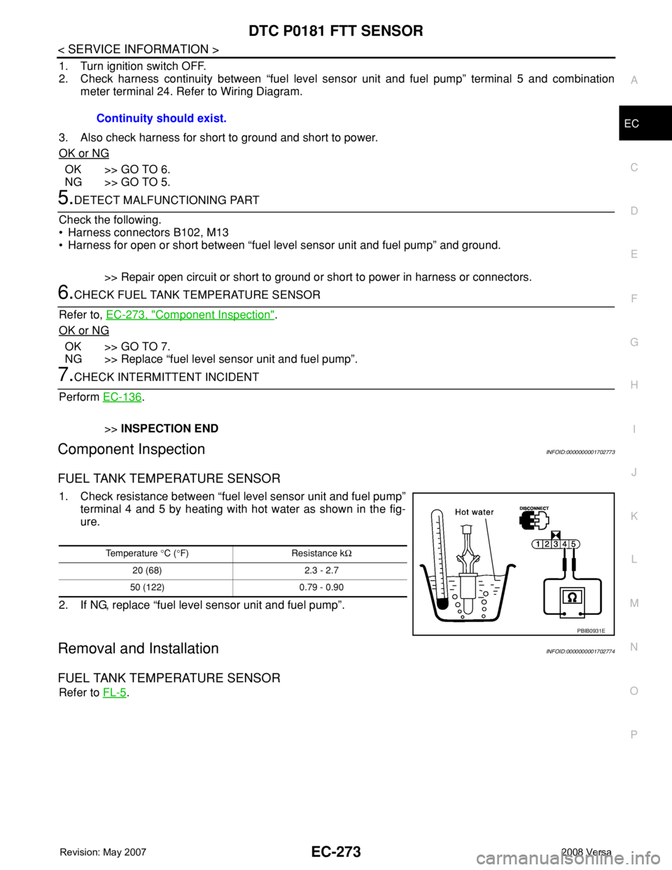
1. Check resistance between “fuel level sensor unit and fuel pump”
terminal 4 and 5 by heating with hot water as shown in the fig-
ure.
2. If NG, replace “fuel level sensor unit and fuel pump”.
Removal and InstallationINFOID:0000000001702774
FUEL TANK TEMPERATURE SENSOR
Refer to FL-5. Continuity should exist.
Temperature °C (°F) Resistance kΩ
20 (68) 2.3 - 2.7
50 (122) 0.79 - 0.90
PBIB0931E
Page 1351 of 2771
DTC P0182, P0183 FTT SENSOR
EC-277
< SERVICE INFORMATION >
C
D
E
F
G
H
I
J
K
L
MA
EC
N
P O
2. Check harness continuity between “fuel level sensor unit and fuel pump” terminal 5 and combination
meter terminal 24. Refer to Wiring Diagram.
3. Also check harness for short to ground and short to power.
OK or NG
OK >> GO TO 6.
NG >> GO TO 5.
5.DETECT MALFUNCTIONING PART
Check the following.
• Harness connectors B102, M13
• Harness for open or short between “fuel level sensor unit and fuel pump” and ground
>> Repair open circuit or short to ground or short to power in harness or connector.
6.CHECK FUEL TANK TEMPERATURE SENSOR
Refer to, EC-277, "
Component Inspection".
OK or NG
OK >> GO TO 7.
NG >> Replace “fuel level sensor unit and fuel pump”.
7.CHECK INTERMITTENT INCIDENT
Perform EC-136
.
>>INSPECTION END
Component InspectionINFOID:0000000001702780
FUEL TANK TEMPERATURE SENSOR
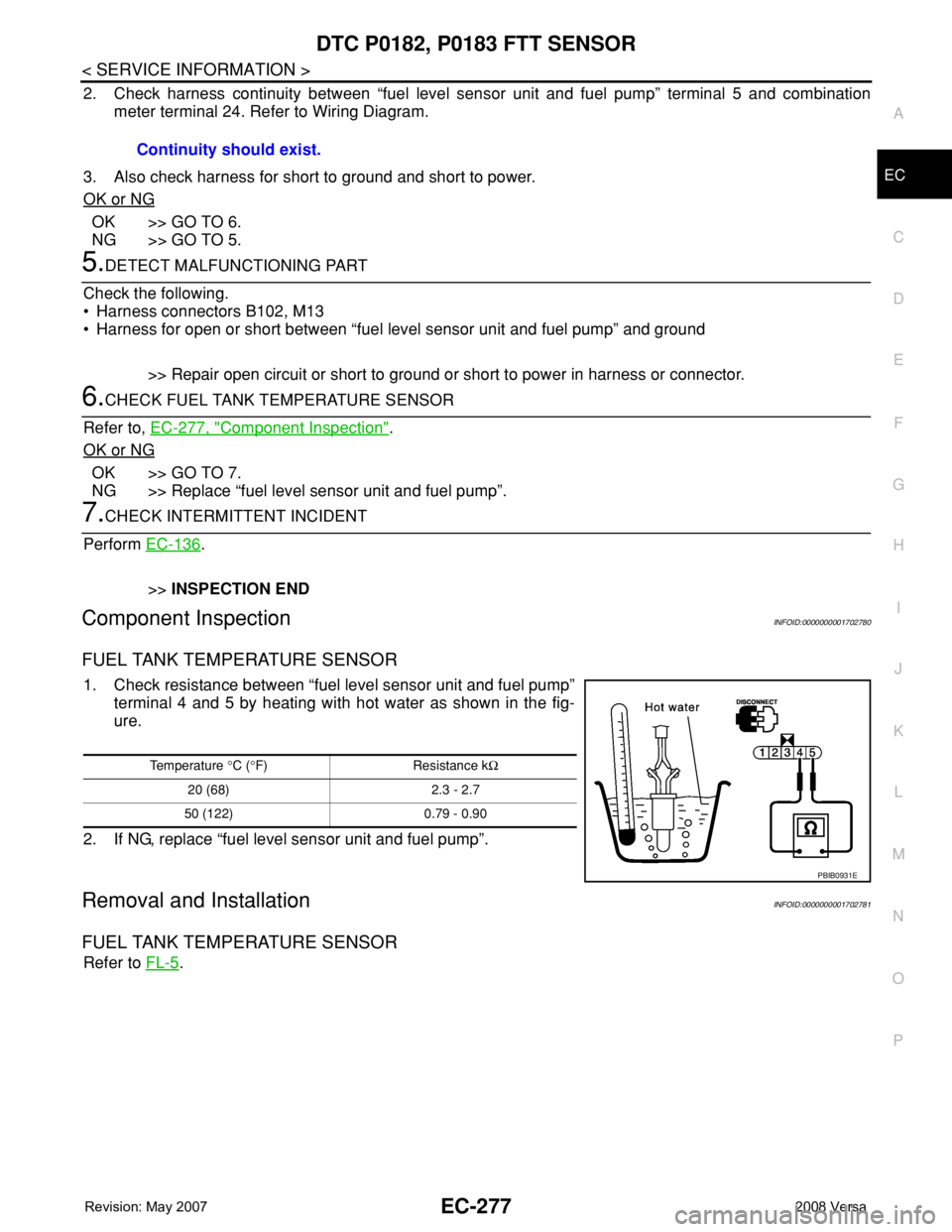
1. Check resistance between “fuel level sensor unit and fuel pump”
terminal 4 and 5 by heating with hot water as shown in the fig-
ure.
2. If NG, replace “fuel level sensor unit and fuel pump”.
Removal and InstallationINFOID:0000000001702781
FUEL TANK TEMPERATURE SENSOR
Refer to FL-5. Continuity should exist.
Temperature °C (°F) Resistance kΩ
20 (68) 2.3 - 2.7
50 (122) 0.79 - 0.90
PBIB0931E
Page 1455 of 2771
DTC P0456 EVAP CONTROL SYSTEM
EC-381
< SERVICE INFORMATION >
C
D
E
F
G
H
I
J
K
L
MA
EC
N
P O
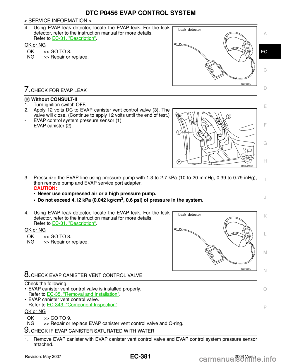
4. Using EVAP leak detector, locate the EVAP leak. For the leak
detector, refer to the instruction manual for more details.
Refer to EC-31, "
Description".
OK or NG
OK >> GO TO 8.
NG >> Repair or replace.
7.CHECK FOR EVAP LEAK
Without CONSULT-II
1. Turn ignition switch OFF.
2. Apply 12 volts DC to EVAP canister vent control valve (3). The
valve will close. (Continue to apply 12 volts until the end of test.)
- EVAP control system pressure sensor (1)
- EVAP canister (2)
3. Pressurize the EVAP line using pressure pump with 1.3 to 2.7 kPa (10 to 20 mmHg, 0.39 to 0.79 inHg),
then remove pump and EVAP service port adapter.
CAUTION:
• Never use compressed air or a high pressure pump.
• Do not exceed 4.12 kPa (0.042 kg/cm
2, 0.6 psi) of pressure in the system.
4. Using EVAP leak detector, locate the EVAP leak. For the leak
detector, refer to the instruction manual for more details.
Refer to EC-31, "
Description".
OK or NG
OK >> GO TO 8.
NG >> Repair or replace.
8.CHECK EVAP CANISTER VENT CONTROL VALVE
Check the following.
• EVAP canister vent control valve is installed properly.
Refer to EC-35, "
Removal and Installation".
• EVAP canister vent control valve.
Refer to EC-343, "
Component Inspection".
OK or NG
OK >> GO TO 9.
NG >> Repair or replace EVAP canister vent control valve and O-ring.
9.CHECK IF EVAP CANISTER SATURATED WITH WATER
1. Remove EVAP canister with EVAP canister vent control valve and EVAP control system pressure sensor
attached.
SEF200U
BBIA0693E
SEF200U
Page 1487 of 2771
DTC P1217 ENGINE OVER TEMPERATURE
EC-413
< SERVICE INFORMATION >
C
D
E
F
G
H
I
J
K
L
MA
EC
N
P O Cooling Fan Relay Operation
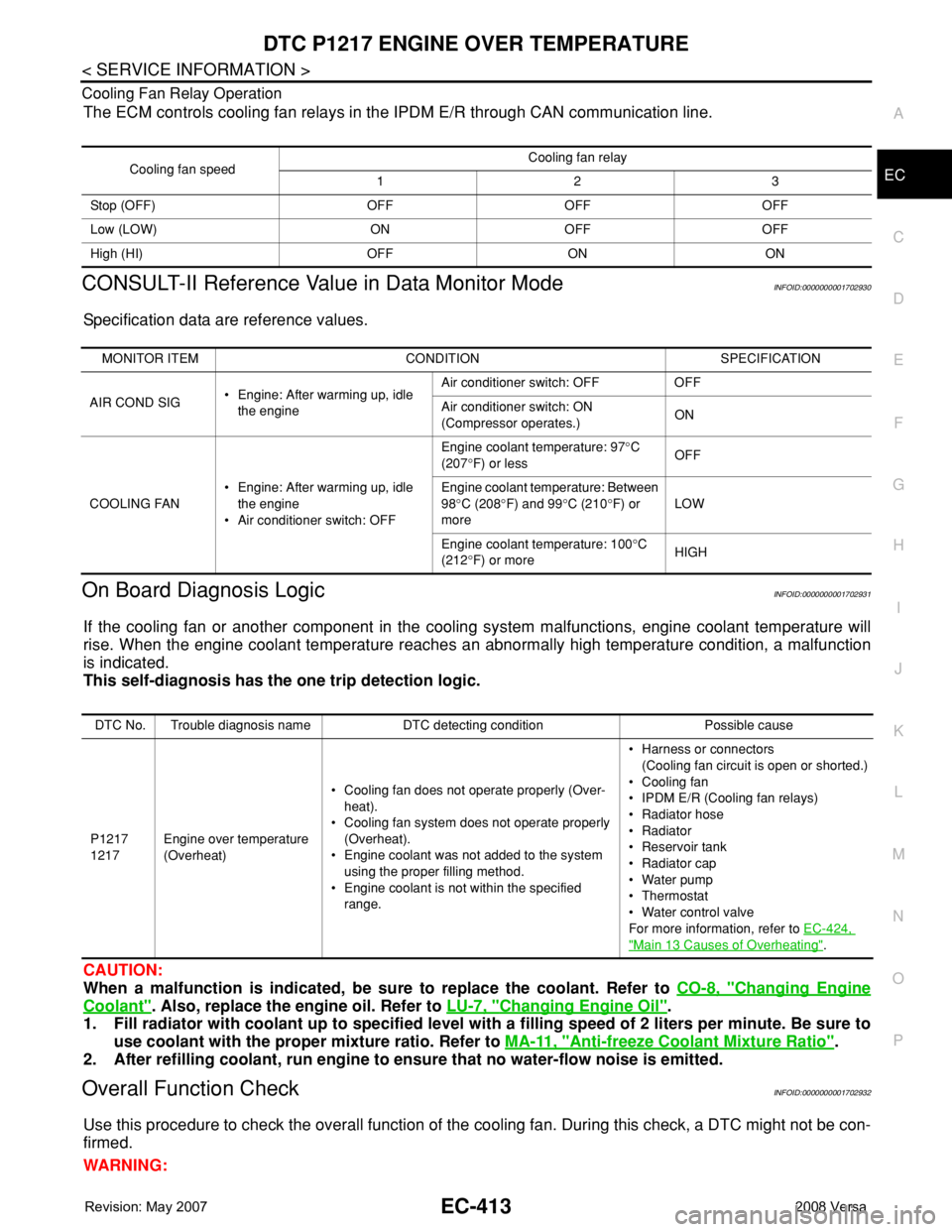
The ECM controls cooling fan relays in the IPDM E/R through CAN communication line.
CONSULT-II Reference Value in Data Monitor ModeINFOID:0000000001702930
Specification data are reference values.
On Board Diagnosis LogicINFOID:0000000001702931
If the cooling fan or another component in the cooling system malfunctions, engine coolant temperature will
rise. When the engine coolant temperature reaches an abnormally high temperature condition, a malfunction
is indicated.
This self-diagnosis has the one trip detection logic.
CAUTION:
When a malfunction is indicated, be sure to replace the coolant. Refer to CO-8, "
Changing Engine
Coolant". Also, replace the engine oil. Refer to LU-7, "Changing Engine Oil".
1. Fill radiator with coolant up to specified level with a filling speed of 2 liters per minute. Be sure to
use coolant with the proper mixture ratio. Refer to MA-11, "
Anti-freeze Coolant Mixture Ratio".
2. After refilling coolant, run engine to ensure that no water-flow noise is emitted.
Overall Function CheckINFOID:0000000001702932
Use this procedure to check the overall function of the cooling fan. During this check, a DTC might not be con-
firmed.
WARNING:
Cooling fan speedCooling fan relay
123
Stop (OFF) OFF OFF OFF
Low (LOW) ON OFF OFF
High (HI) OFF ON ON
MONITOR ITEM CONDITION SPECIFICATION
AIR COND SIG• Engine: After warming up, idle
the engineAir conditioner switch: OFF OFF
Air conditioner switch: ON
(Compressor operates.)ON
COOLING FAN• Engine: After warming up, idle
the engine
• Air conditioner switch: OFFEngine coolant temperature: 97°C
(207°F) or lessOFF
Engine coolant temperature: Between
98°C (208°F) and 99°C (210°F) or
moreLOW
Engine coolant temperature: 100°C
(212°F) or moreHIGH
DTC No. Trouble diagnosis name DTC detecting condition Possible cause
P1217
1217Engine over temperature
(Overheat)• Cooling fan does not operate properly (Over-
heat).
• Cooling fan system does not operate properly
(Overheat).
• Engine coolant was not added to the system
using the proper filling method.
• Engine coolant is not within the specified
range.• Harness or connectors
(Cooling fan circuit is open or shorted.)
• Cooling fan
• IPDM E/R (Cooling fan relays)
•Radiator hose
•Radiator
• Reservoir tank
•Radiator cap
• Water pump
•Thermostat
• Water control valve
For more information, refer to EC-424,
"Main 13 Causes of Overheating".
Page 1493 of 2771

DTC P1217 ENGINE OVER TEMPERATURE
EC-419
< SERVICE INFORMATION >
C
D
E
F
G
H
I
J
K
L
MA
EC
N
P O
5. Restart engine and make sure that cooling fan operate at higher
speed than low speed.
OK or NG
OK >> GO TO 6.
NG >> Check cooling fan high speed control circuit. (Go to
"PROCEDURE A".)
6.CHECK COOLING SYSTEM FOR LEAK
Refer to CO-8
.
OK or NG
OK >> GO TO 8.
NG >> GO TO 7.
7.DETECT MALFUNCTIONING PART
Check the following for leak.
•Hose
• Radiator
• Water pump (Refer to CO-16
.)
>> Repair or replace.
8.CHECK RADIATOR CAP
Refer to CO-11
.
OK or NG
OK >> GO TO 9.
NG >> Replace radiator cap.
9.CHECK COMPONENT PARTS
Check the following;.
• Thermostat. (Refer to CO-16
.)
• Water control valve. (Refer to CO-19
.)
• Engine coolant temperature sensor. (Refer to EC-191, "
Component Inspection".)
OK or NG
OK >> GO TO 10.
NG >> Replace malfunctioning component.
10.CHECK MAIN 13 CAUSES
If the cause cannot be isolated, go to EC-424, "
Main 13 Causes of Overheating".
>>INSPECTION END
PROCEDURE A
1.CHECK POWER SUPPLY CIRCUIT
1. Turn ignition switch OFF.
2. Disconnect IPDM E/R harness connector E44.
SEF023R
Page 1496 of 2771
EC-422
< SERVICE INFORMATION >
DTC P1217 ENGINE OVER TEMPERATURE
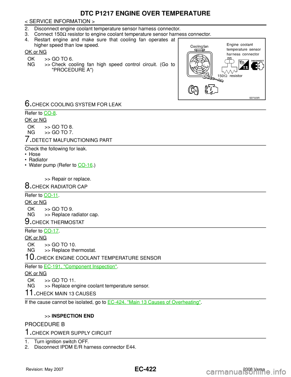
2. Disconnect engine coolant temperature sensor harness connector.
3. Connect 150Ω resistor to engine coolant temperature sensor harness connector.
4. Restart engine and make sure that cooling fan operates at
higher speed than low speed.
OK or NG
OK >> GO TO 6.
NG >> Check cooling fan high speed control circuit. (Go to
"PROCEDURE A")
6.CHECK COOLING SYSTEM FOR LEAK
Refer to CO-8
.
OK or NG
OK >> GO TO 8.
NG >> GO TO 7.
7.DETECT MALFUNCTIONING PART
Check the following for leak.
•Hose
• Radiator
• Water pump (Refer to CO-16
.)
>> Repair or replace.
8.CHECK RADIATOR CAP
Refer to CO-11
.
OK or NG
OK >> GO TO 9.
NG >> Replace radiator cap.
9.CHECK THERMOSTAT
Refer to CO-17
.
OK or NG
OK >> GO TO 10.
NG >> Replace thermostat.
10.CHECK ENGINE COOLANT TEMPERATURE SENSOR
Refer to EC-191, "
Component Inspection".
OK or NG
OK >> GO TO 11.
NG >> Replace engine coolant temperature sensor.
11 .CHECK MAIN 13 CAUSES
If the cause cannot be isolated, go to EC-424, "
Main 13 Causes of Overheating".
>>INSPECTION END
PROCEDURE B
1.CHECK POWER SUPPLY CIRCUIT
1. Turn ignition switch OFF.
2. Disconnect IPDM E/R harness connector E44.
SEF023R
Page 1688 of 2771
NOISE, VIBRATION AND HARSHNESS (NVH) TROUBLESHOOTING
EM-11
< SERVICE INFORMATION >
C
D
E
F
G
H
I
J
K
L
MA
EM
N
P O
NOISE, VIBRATION AND HARSHNESS (NVH) TROUBLESHOOTING
NVH Troubleshooting - Engine NoiseINFOID:0000000001702472
WBIA0769E
1. Piston pin noise 2. Piston slap noise 3. Main bearing noise
4. Water pump noise 5. Timing chain and tensioner noise 6. Drive belt noise (stick/slipping)
7. Tappet noise 8. Camshaft bearing noise 9. Connecting rod noise
A. Rotational mechanism B. Water pump C. Timing chain