2008 NISSAN TIIDA horn
[x] Cancel search: hornPage 502 of 2771
BL-68
< SERVICE INFORMATION >
REMOTE KEYLESS ENTRY SYSTEM
OK or NG
OK >> Replace IPDM E/R. Refer to PG-26, "Removal and
Installation of IPDM E/R"
NG >> GO TO 3.
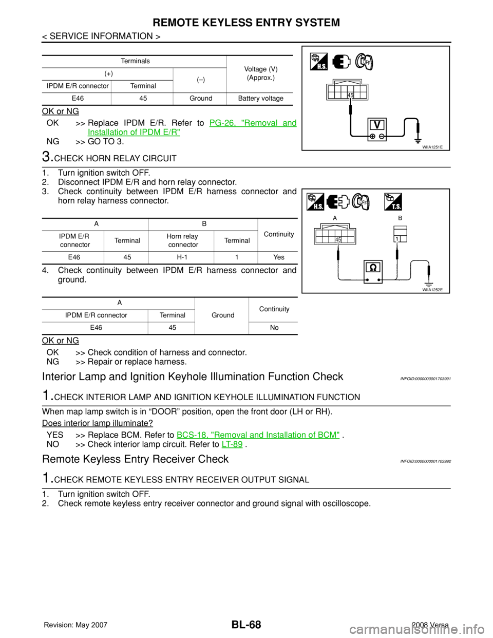
3.CHECK HORN RELAY CIRCUIT
1. Turn ignition switch OFF.
2. Disconnect IPDM E/R and horn relay connector.
3. Check continuity between IPDM E/R harness connector and
horn relay harness connector.
4. Check continuity between IPDM E/R harness connector and
ground.
OK or NG
OK >> Check condition of harness and connector.
NG >> Repair or replace harness.
Interior Lamp and Ignition Keyhole Illumination Function CheckINFOID:0000000001703991
1.CHECK INTERIOR LAMP AND IGNITION KEYHOLE ILLUMINATION FUNCTION
When map lamp switch is in “DOOR” position, open the front door (LH or RH).
Does interior lamp illuminate?
YES >> Replace BCM. Refer to BCS-18, "Removal and Installation of BCM" .
NO >> Check interior lamp circuit. Refer to LT- 8 9
.
Remote Keyless Entry Receiver CheckINFOID:0000000001703992
1.CHECK REMOTE KEYLESS ENTRY RECEIVER OUTPUT SIGNAL
1. Turn ignition switch OFF.
2. Check remote keyless entry receiver connector and ground signal with oscilloscope.
Te r m i n a l s
Voltage (V)
(Approx.) (+)
(–)
IPDM E/R connector Terminal
E46 45 Ground Battery voltage
WIIA1251E
AB
Continuity
IPDM E/R
connectorTe r m i n a lHorn relay
connectorTe r m i n a l
E46 45 H-1 1 Yes
A
GroundContinuity
IPDM E/R connector Terminal
E46 45 No
WIIA1252E
Page 509 of 2771
INTELLIGENT KEY SYSTEM
BL-75
< SERVICE INFORMATION >
C
D
E
F
G
H
J
K
L
MA
B
BL
N
O
P
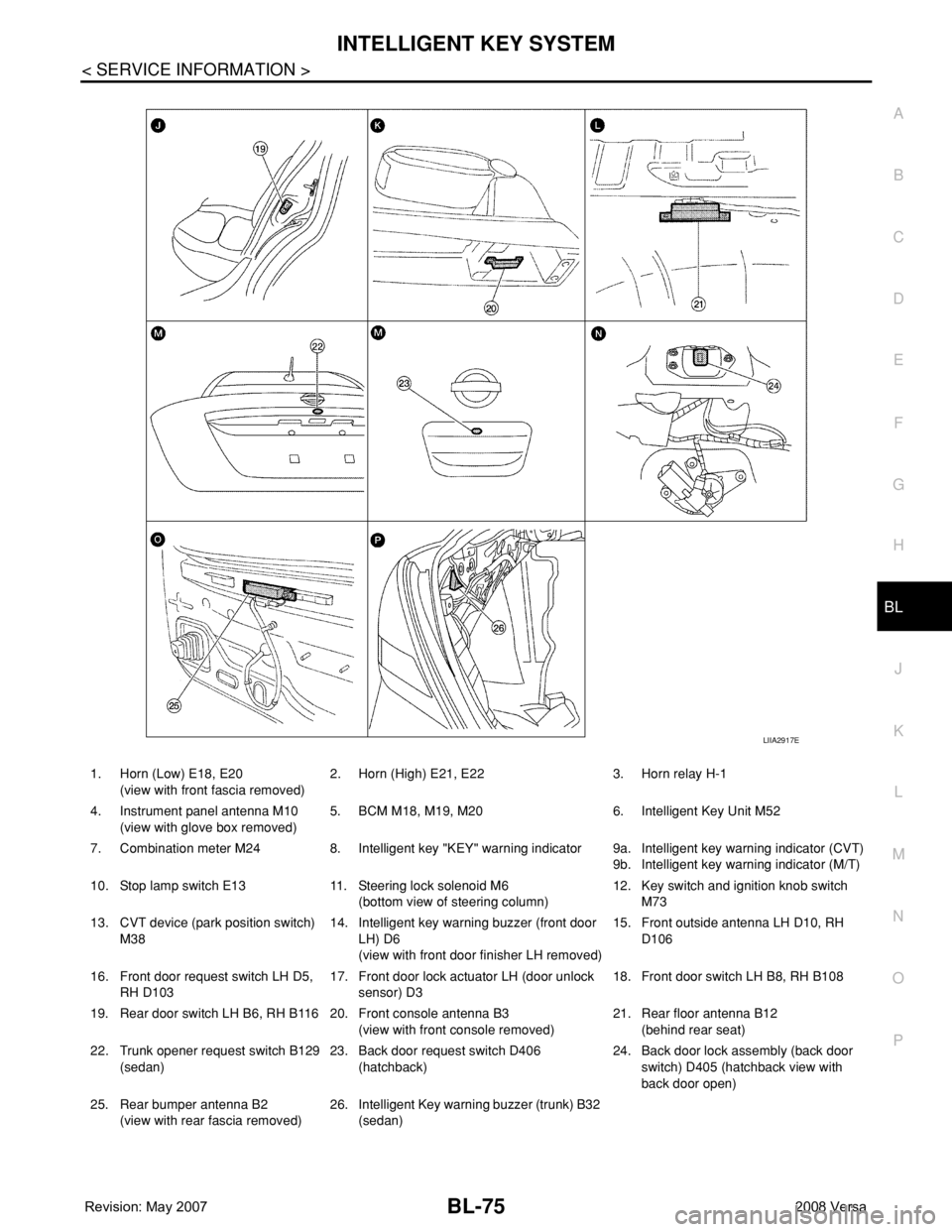
1. Horn (Low) E18, E20
(view with front fascia removed)2. Horn (High) E21, E22 3. Horn relay H-1
4. Instrument panel antenna M10
(view with glove box removed)5. BCM M18, M19, M20 6. Intelligent Key Unit M52
7. Combination meter M24 8. Intelligent key "KEY" warning indicator 9a.
9b.Intelligent key warning indicator (CVT)
Intelligent key warning indicator (M/T)
10. Stop lamp switch E13 11. Steering lock solenoid M6
(bottom view of steering column)12. Key switch and ignition knob switch
M73
13. CVT device (park position switch)
M3814. Intelligent key warning buzzer (front door
LH) D6
(view with front door finisher LH removed)15. Front outside antenna LH D10, RH
D106
16. Front door request switch LH D5,
RH D10317. Front door lock actuator LH (door unlock
sensor) D318. Front door switch LH B8, RH B108
19. Rear door switch LH B6, RH B116 20. Front console antenna B3
(view with front console removed)21. Rear floor antenna B12
(behind rear seat)
22. Trunk opener request switch B129
(sedan)23. Back door request switch D406
(hatchback)24. Back door lock assembly (back door
switch) D405 (hatchback view with
back door open)
25. Rear bumper antenna B2
(view with rear fascia removed)26. Intelligent Key warning buzzer (trunk) B32
(sedan)
LIIA2917E
Page 513 of 2771
INTELLIGENT KEY SYSTEM
BL-79
< SERVICE INFORMATION >
C
D
E
F
G
H
J
K
L
MA
B
BL
N
O
P System Diagram
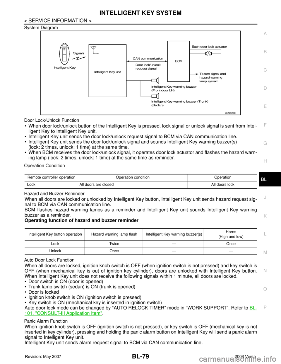
Door Lock/Unlock Function
• When door lock/unlock button of the Intelligent Key is pressed, lock signal or unlock signal is sent from Intel-
ligent Key to Intelligent Key unit.
• Intelligent Key unit sends the door lock/unlock request signal to BCM via CAN communication line.
• Intelligent Key unit sends the door lock/unlock signal and sounds Intelligent Key warning buzzer(s)
(lock: 2 times, unlock: 1 time) at the same time.
• When BCM receives the door lock/unlock signal, it operates door lock actuator and flashes the hazard warn-
ing lamp (lock: 2 times, unlock: 1 time) at the same time as reminder.
Operation Condition
Hazard and Buzzer Reminder
When all doors are locked or unlocked by Intelligent Key button, Intelligent Key unit sends hazard request sig-
nal to BCM via CAN communication line.
BCM flashes hazard warning lamps as a reminder and Intelligent Key unit sounds Intelligent Key warning
buzzer as a reminder.
Operating function of hazard and buzzer reminder
Auto Door Lock Function
When all doors are locked, ignition knob switch is OFF (when ignition switch is not pressed) and key switch is
OFF (when mechanical key is out of ignition key cylinder), doors are unlocked with Intelligent Key button.
When Intelligent Key unit does not receive the following signals within 1 minute, all doors are locked.
• Door switch is ON (door is opened)
• Trunk lamp switch (sedan) is ON (trunk is opened)
• Door is locked
• Ignition knob switch is ON (ignition switch is pressed)
• Key switch is ON (mechanical key is inserted in ignition switch)
Auto door lock mode can be changed by “AUTO RELOCK TIMER” mode in “WORK SUPPORT”. Refer to BL-
101, "CONSULT-III Application Item".
Panic Alarm Function
When ignition knob switch is OFF (ignition switch is not pressed), or key switch is OFF (mechanical key is not
inserted in key cylinder), pressing and holding the panic alarm button on Intelligent Key will send a panic alarm
signal to Intelligent Key unit.
Intelligent Key unit sends alarm request signal to BCM via CAN communication line.
LIIA2927E
Remote controller operation Operation condition Operation
Lock All doors are closed All doors lock
Intelligent Key button operation Hazard warning lamp flash Intelligent Key warning buzzer(s)Horns
(High and low)
Lock Twice — Once
Unlock Once — —
Page 514 of 2771

BL-80
< SERVICE INFORMATION >
INTELLIGENT KEY SYSTEM
BCM sends headlamp request signal and horn signal to IPDM E/R. Then, IPDM E/R turns on and off head-
lamp and horn intermittently.
The headlamp flashes and the horn sounds intermittently.
The alarm automatically turns off:
• After 25 seconds
• When Intelligent Key unit receives any signal from remote controller of Intelligent Key
• When door request switch is pressed (Intelligent Key is outside vehicle)
Panic alarm function's press and holding time value can be changed in “PANIC ALARM DELAY” mode in
“WORK SUPPORT”. Refer to BL-101, "
CONSULT-III Application Item".
List of Operation Related Parts
Parts marked with × are the parts related to operation.
ENGINE START FUNCTION
When the registered Intelligent Key is carried, the engine can be started without inserting the key.
When ignition knob switch is ON (press ignition switch), Intelligent Key unit searches Intelligent Key in the
vehicle using inside key antenna.
Then Intelligent Key is inside the vehicle, it performs the following operation.
• Illuminate green “KEY” warning lamp in combination meter.
• Released steering lock and ignition switch can be turned from OFF to ACC, ON or START position.
NOTE:
If Intelligent Key is not registered, “KEY” warning lamp in combination meter illuminates red.
• Intelligent Key sends engine start signal to BCM via CAN communication line.
Remote keyless entry functions
Intelligent Key
Key switch
Ignition knob switch
Door request switch
Door switch
Back door lock assembly (back door switch)
Door lock actuator
Intelligent Key warning buzzer
Intelligent Key unit
CAN communication system
BCM
Hazard warning lamp
Horn
IPDM E/R
Head lamp
Door lock/unlock function by Intelligent Key button×××××××
Hazard and buzzer reminder function×××××
Auto door lock function×× ××× ×××
Panic alarm function×××× ××× ×××
WIIA1282E
Page 536 of 2771

BL-102
< SERVICE INFORMATION >
INTELLIGENT KEY SYSTEM
* : Sedan
WORK SUPPORT
Te s t i t e m D e s c r i p t i o n
DOOR LOCK/UNLOCKThis test is able to check door lock/unlock operation.
• The all door lock actuators are unlocked when “ALL UNLK” on CONSULT-III screen is touched.
• The all door lock actuators are locked when “LOCK” on CONSULT-III screen is touched.
ANTENNAThis test is able to check Intelligent Key antenna operation.
When the following conditions are met, hazard warning lamps flash.
• Inside key antenna (front console) detects Intelligent Key, when “ROOM ANT1” on CONSULT-
III screen is touched.
• Inside key antenna (instrument panel and rear floor) detects Intelligent Key, when “ROOM
ANT2” on CONSULT-III screen is touched.
• Outside key antenna (driver side) detects Intelligent Key, when “DRIVER ANT” on CONSULT-III
screen is touched.
• Outside key antenna (passenger side) detects Intelligent Key, when “ASSIST ANT” on CON-
SULT-III screen is touched.
• Outside key antenna (rear bumper) detects Intelligent Key, when “BK DOOR ANT” on CON-
SULT-III screen is touched.
OUTSIDE BUZZER(S)
(DRIVER DOOR), (TRUNK)
*This test is able to check Intelligent Key warning buzzer operation.
Intelligent Key warning buzzer sounds when “ON” on CONSULT-III screen is touched.
INSIDE BUZZER
(CHIME)This test is able to check Intelligent Key warning chime (Instrument panel) operation.
• Take away warning chime sounds when “TAKE OUT” on CONSULT-III screen is touched.
• Ignition switch warning chime sounds when “KNOB” on CONSULT-III screen is touched.
• Ignition key warning chime sounds when “KEY” on CONSULT-III screen is touched.
INDICATORThis test is able to check warning lamp operation.
• “KEY” Warning lamp (Green) illuminates when “BLUE ON” on CONSULT-III screen is touched.
• “KEY” Warning lamp (Red) illuminates when “RED ON” on CONSULT-III screen is touched.
• “LOCK” Warning lamp illuminates when “KNOB ON” on CONSULT-III screen is touched.
• “KEY” Warning lamp (Green) flashes when “BLUE IND” on CONSULT-III screen is touched.
• “KEY” Warning lamp (RED) flashes when “BLUE IND” on CONSULT-III screen is touched.
• “P-SHIFT” Warning lamp flashes when “KNOB ON” on CONSULT-III screen is touched.
Monitor item Description
CONFIRM KEY FOB ID It can be checked whether Intelligent Key ID code is registered or not in this mode.
TAKE OUT FROM WINDOW
WARNTake away warning chime (from window) mode can be changed to operate (ON) or not operate
(OFF) with this mode. The operation mode will be changed when “CHANGE SETT” on CONSULT-
III screen is touched.
LOW BAT OF KEY FOB WARNIntelligent Key low battery warning mode can be changed to operate (ON) or not operate (OFF)
with this mode. The operation mode will be changed when “CHANGE SETT” on CONSULT-III
screen is touched.
ANSWER BACK FUNCTIONBuzzer reminder function mode by Intelligent button can be changed to operate (ON) or not oper-
ate (OFF) with this mode. The operation mode will be changed when “CHANGE SETT” on CON-
SULT-III screen is touched.
SELECTIVE UNLOCK FUNC-
TIONSelective unlock function mode can be changed to operate (ON) or not operate (OFF) with this
mode. The operation mode will be changed when “CHANGE SETT” on CONSULT-III screen is
touched.
ANTI KEY LOCK IN FUNCTIONKey reminder function mode can be changed to operate (ON) or not operate (OFF) with this mode.
The operation mode will be changed when “CHANGE SETT” on CONSULT-III screen is touched.
HORN WITH KEYLESS LOCKHorn reminder function mode by Intelligent Key remote control button can be changed to operate
(ON) or not operate (OFF) with this mode. The operation mode will be changed when “CHANGE
SETT” on CONSULT-III screen is touched.
HAZARD ANSWER BACKHazard reminder function mode can be selected from the following with this mode. The operation
mode will be changed when “CHANGE SETT” on CONSULT-III screen is touched.
• LOCK ONLY: Door lock operation only
• UNLOCK ONLY: Door unlock operation only
• LOCK/UNLOCK: Lock/Unlock operation
• OFF: Non-operation
Page 541 of 2771
INTELLIGENT KEY SYSTEM
BL-107
< SERVICE INFORMATION >
C
D
E
F
G
H
J
K
L
MA
B
BL
N
O
P
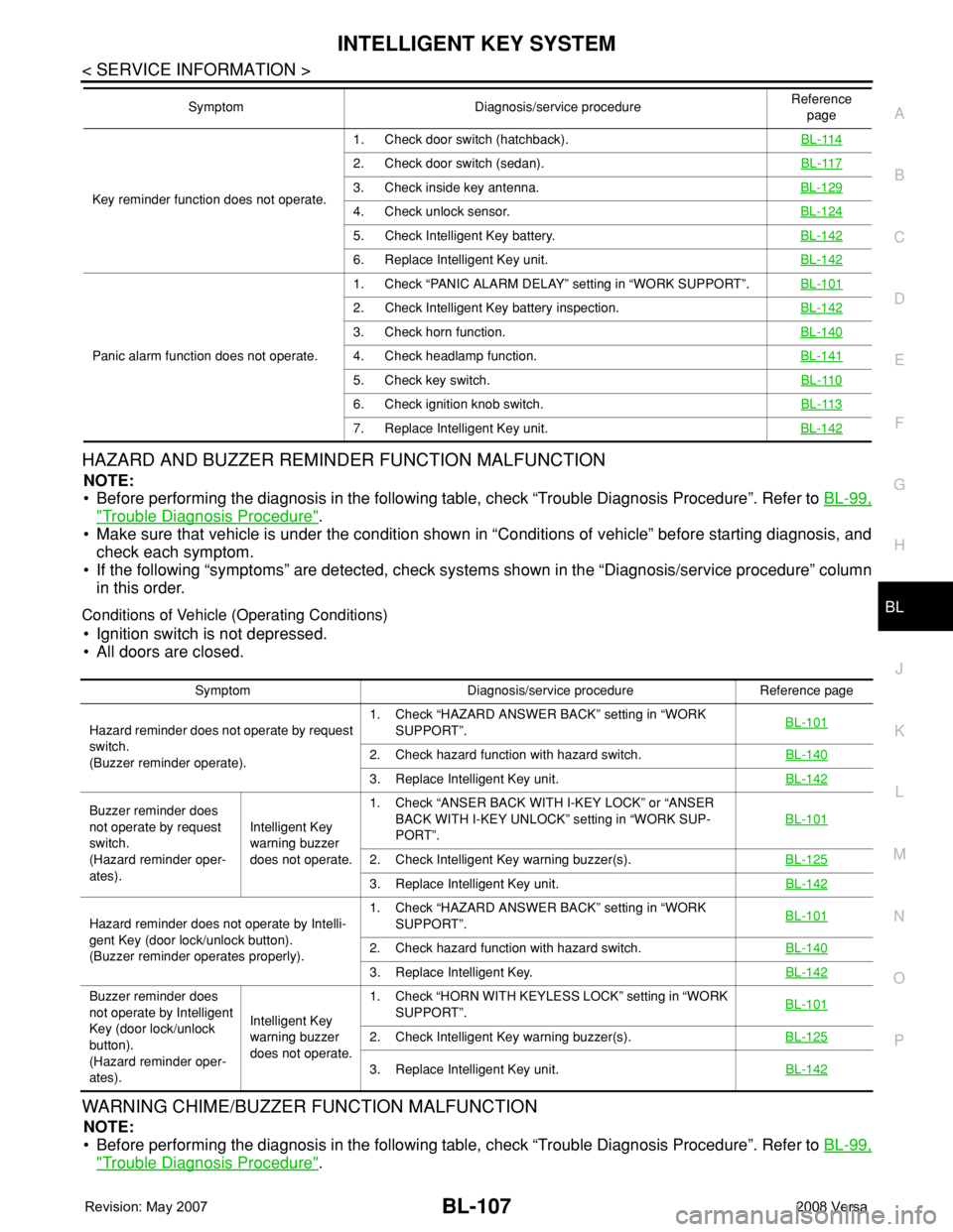
HAZARD AND BUZZER REMINDER FUNCTION MALFUNCTION
NOTE:
• Before performing the diagnosis in the following table, check “Trouble Diagnosis Procedure”. Refer to BL-99,
"Trouble Diagnosis Procedure".
• Make sure that vehicle is under the condition shown in “Conditions of vehicle” before starting diagnosis, and
check each symptom.
• If the following “symptoms” are detected, check systems shown in the “Diagnosis/service procedure” column
in this order.
Conditions of Vehicle (Operating Conditions)
• Ignition switch is not depressed.
• All doors are closed.
WARNING CHIME/BUZZER FUNCTION MALFUNCTION
NOTE:
• Before performing the diagnosis in the following table, check “Trouble Diagnosis Procedure”. Refer to BL-99,
"Trouble Diagnosis Procedure".
Key reminder function does not operate.1. Check door switch (hatchback).BL-114
2. Check door switch (sedan).BL-117
3. Check inside key antenna.BL-129
4. Check unlock sensor.BL-124
5. Check Intelligent Key battery.BL-142
6. Replace Intelligent Key unit.BL-142
Panic alarm function does not operate.1. Check “PANIC ALARM DELAY” setting in “WORK SUPPORT”.BL-101
2. Check Intelligent Key battery inspection.BL-142
3. Check horn function.BL-140
4. Check headlamp function.BL-141
5. Check key switch.BL-110
6. Check ignition knob switch.BL-113
7. Replace Intelligent Key unit.BL-142
Symptom Diagnosis/service procedureReference
page
Symptom Diagnosis/service procedure Reference page
Hazard reminder does not operate by request
switch.
(Buzzer reminder operate).1. Check “HAZARD ANSWER BACK” setting in “WORK
SUPPORT”.BL-101
2. Check hazard function with hazard switch.BL-140
3. Replace Intelligent Key unit.BL-142
Buzzer reminder does
not operate by request
switch.
(Hazard reminder oper-
ates).Intelligent Key
warning buzzer
does not operate.1. Check “ANSER BACK WITH I-KEY LOCK” or “ANSER
BACK WITH I-KEY UNLOCK” setting in “WORK SUP-
PORT”.BL-101
2. Check Intelligent Key warning buzzer(s).BL-125
3. Replace Intelligent Key unit.BL-142
Hazard reminder does not operate by Intelli-
gent Key (door lock/unlock button).
(Buzzer reminder operates properly).1. Check “HAZARD ANSWER BACK” setting in “WORK
SUPPORT”.BL-101
2. Check hazard function with hazard switch.BL-140
3. Replace Intelligent Key.BL-142
Buzzer reminder does
not operate by Intelligent
Key (door lock/unlock
button).
(Hazard reminder oper-
ates).Intelligent Key
warning buzzer
does not operate.1. Check “HORN WITH KEYLESS LOCK” setting in “WORK
SUPPORT”.BL-101
2. Check Intelligent Key warning buzzer(s).BL-125
3. Replace Intelligent Key unit.BL-142
Page 574 of 2771
BL-140
< SERVICE INFORMATION >
INTELLIGENT KEY SYSTEM
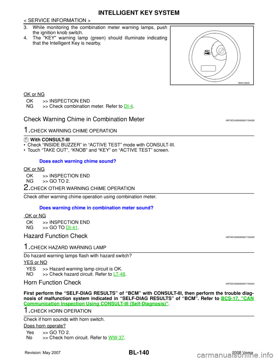
3. While monitoring the combination meter warning lamps, push
the ignition knob switch.
4. The "KEY" warning lamp (green) should illuminate indicating
that the Intelligent Key is nearby.
OK or NG
OK >> INSPECTION END
NG >> Check combination meter. Refer to DI-4
.
Check Warning Chime in Combination MeterINFOID:0000000001704038
1.CHECK WARNING CHIME OPERATION
With CONSULT-III
• Check “INSIDE BUZZER” in “ACTIVE TEST” mode with CONSULT-III.
• Touch “TAKE OUT”, “KNOB” and “KEY” on “ACTIVE TEST” screen.
OK or NG
OK >> INSPECTION END
NG >> GO TO 2.
2.CHECK OTHER WARNING CHIME OPERATION
Check other warning chime operation using combination meter.
OK or NG
OK >> INSPECTION END
NG >> GO TO DI-41
.
Hazard Function CheckINFOID:0000000001704039
1.CHECK HAZARD WARNING LAMP
Do hazard warning lamps flash with hazard switch?
YES or NO
YES >> Hazard warning lamp circuit is OK.
NO >> Check hazard circuit. Refer to LT- 4 8
.
Horn Function CheckINFOID:0000000001704040
First perform the “SELF-DIAG RESULTS” of “BCM” with CONSULT-III, then perform the trouble diag-
nosis of malfunction system indicated in “SELF-DIAG RESULTS” of “BCM”. Refer to BCS-17, "
CAN
Communication Inspection Using CONSULT-III (Self-Diagnosis)".
1.CHECK HORN OPERATION
Check if horn sounds with horn switch.
Does horn operate?
Ye s > > G O T O 2 .
No >> Check horn circuit. Refer to WW-37
.
WIIA1264E
Does each warning chime sound?
Does warning chime in combination meter sound?
Page 575 of 2771
INTELLIGENT KEY SYSTEM
BL-141
< SERVICE INFORMATION >
C
D
E
F
G
H
J
K
L
MA
B
BL
N
O
P
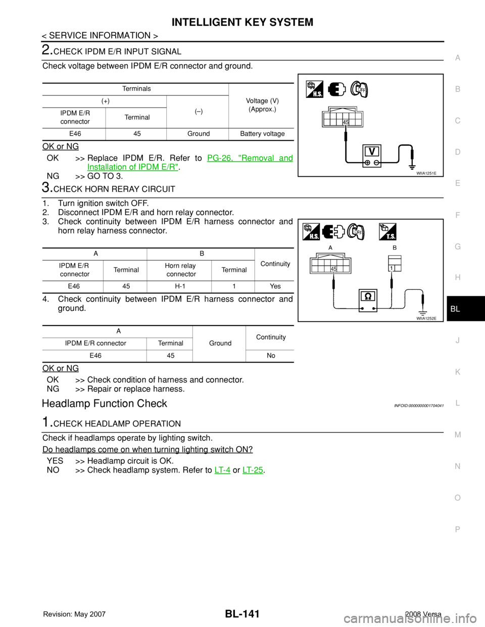
2.CHECK IPDM E/R INPUT SIGNAL
Check voltage between IPDM E/R connector and ground.
OK or NG
OK >> Replace IPDM E/R. Refer to PG-26, "Removal and
Installation of IPDM E/R".
NG >> GO TO 3.
3.CHECK HORN RERAY CIRCUIT
1. Turn ignition switch OFF.
2. Disconnect IPDM E/R and horn relay connector.
3. Check continuity between IPDM E/R harness connector and
horn relay harness connector.
4. Check continuity between IPDM E/R harness connector and
ground.
OK or NG
OK >> Check condition of harness and connector.
NG >> Repair or replace harness.
Headlamp Function CheckINFOID:0000000001704041
1.CHECK HEADLAMP OPERATION
Check if headlamps operate by lighting switch.
Do headlamps come on when turning lighting switch ON?
YES >> Headlamp circuit is OK.
NO >> Check headlamp system. Refer to LT- 4
or LT- 2 5.
Te r m i n a l s
Voltage (V)
(Approx.) (+)
(–)
IPDM E/R
connectorTe r m i n a l
E46 45 Ground Battery voltage
WIIA1251E
AB
Continuity
IPDM E/R
connectorTe r m i n a lHorn relay
connectorTe r m i n a l
E46 45 H-1 1 Yes
A
GroundContinuity
IPDM E/R connector Terminal
E46 45 No
WIIA1252E