Page 2734 of 2771

WW-1
ELECTRICAL
C
D
E
F
G
H
I
J
L
M
SECTION WW
A
B
WW
N
O
P
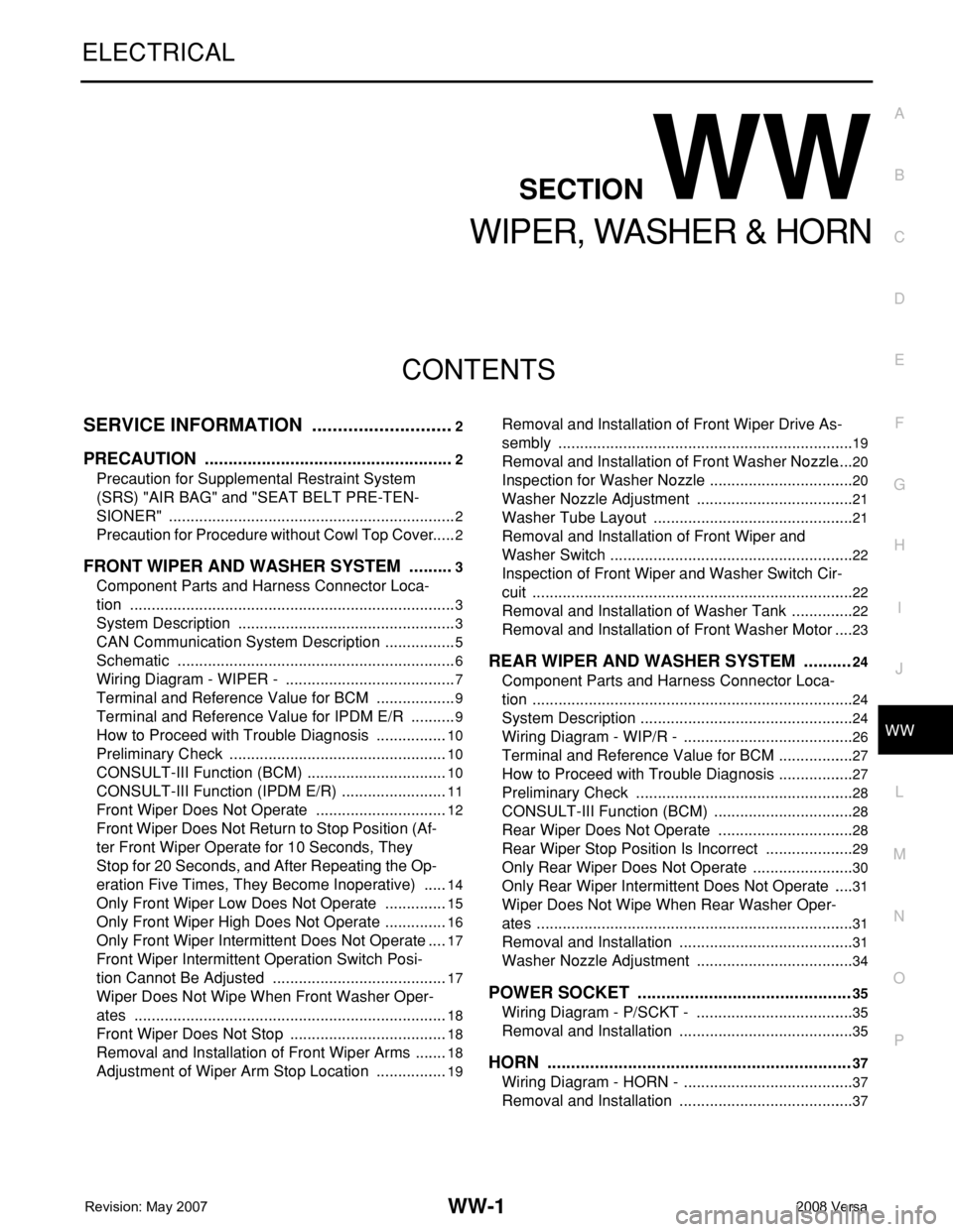
CONTENTS
WIPER, WASHER & HORN
SERVICE INFORMATION ............................2
PRECAUTION .....................................................2
Precaution for Supplemental Restraint System
(SRS) "AIR BAG" and "SEAT BELT PRE-TEN-
SIONER" ...................................................................
2
Precaution for Procedure without Cowl Top Cover ......2
FRONT WIPER AND WASHER SYSTEM ..........3
Component Parts and Harness Connector Loca-
tion ............................................................................
3
System Description ...................................................3
CAN Communication System Description .................5
Schematic .................................................................6
Wiring Diagram - WIPER - ........................................7
Terminal and Reference Value for BCM ...................9
Terminal and Reference Value for IPDM E/R ...........9
How to Proceed with Trouble Diagnosis .................10
Preliminary Check ...................................................10
CONSULT-III Function (BCM) .................................10
CONSULT-III Function (IPDM E/R) .........................11
Front Wiper Does Not Operate ...............................12
Front Wiper Does Not Return to Stop Position (Af-
ter Front Wiper Operate for 10 Seconds, They
Stop for 20 Seconds, and After Repeating the Op-
eration Five Times, They Become Inoperative) ......
14
Only Front Wiper Low Does Not Operate ...............15
Only Front Wiper High Does Not Operate ...............16
Only Front Wiper Intermittent Does Not Operate ....17
Front Wiper Intermittent Operation Switch Posi-
tion Cannot Be Adjusted .........................................
17
Wiper Does Not Wipe When Front Washer Oper-
ates .........................................................................
18
Front Wiper Does Not Stop .....................................18
Removal and Installation of Front Wiper Arms ........18
Adjustment of Wiper Arm Stop Location .................19
Removal and Installation of Front Wiper Drive As-
sembly .....................................................................
19
Removal and Installation of Front Washer Nozzle ....20
Inspection for Washer Nozzle ..................................20
Washer Nozzle Adjustment .....................................21
Washer Tube Layout ...............................................21
Removal and Installation of Front Wiper and
Washer Switch .........................................................
22
Inspection of Front Wiper and Washer Switch Cir-
cuit ...........................................................................
22
Removal and Installation of Washer Tank ...............22
Removal and Installation of Front Washer Motor ....23
REAR WIPER AND WASHER SYSTEM ..........24
Component Parts and Harness Connector Loca-
tion ...........................................................................
24
System Description ..................................................24
Wiring Diagram - WIP/R - ........................................26
Terminal and Reference Value for BCM ..................27
How to Proceed with Trouble Diagnosis ..................27
Preliminary Check ...................................................28
CONSULT-III Function (BCM) .................................28
Rear Wiper Does Not Operate ................................28
Rear Wiper Stop Position Is Incorrect .....................29
Only Rear Wiper Does Not Operate ........................30
Only Rear Wiper Intermittent Does Not Operate .....31
Wiper Does Not Wipe When Rear Washer Oper-
ates ..........................................................................
31
Removal and Installation .........................................31
Washer Nozzle Adjustment .....................................34
POWER SOCKET .............................................35
Wiring Diagram - P/SCKT - .....................................35
Removal and Installation .........................................35
HORN ................................................................37
Wiring Diagram - HORN - ........................................37
Removal and Installation .........................................37
Page 2770 of 2771
HORN
WW-37
< SERVICE INFORMATION >
C
D
E
F
G
H
I
J
L
MA
B
WW
N
O
P
HORN
Wiring Diagram - HORN -INFOID:0000000001704581
Removal and InstallationINFOID:0000000001704582
REMOVAL
1. Remove the front grille. Refer to EI-20, "Removal and Installation".
WKWA4997E
Page 2771 of 2771
WW-38
< SERVICE INFORMATION >
HORN
2. Disconnect the horn connectors.
3. Remove the horn nuts (A) and remove the horns (1).
INSTALLATION
Installation is in the reverse order of removal.
SKIB5670E