2008 NISSAN TIIDA blower motor
[x] Cancel search: blower motorPage 2371 of 2771
TROUBLE DIAGNOSIS
MTC-33
< SERVICE INFORMATION >
C
D
E
F
G
H
I
K
L
MA
B
MTC
N
O
P
>> GO TO 5.
5.CHECK AIR MIX DOOR CONTROL LINKAGE
Check and verify air mix door mechanism for smooth operation.
OK or NG
OK >> If the symptom still exists, perform a complete operational check. Refer to MTC-30, "Operational
Check" If other symptoms exist, refer to MTC-22, "How to Perform Trouble Diagnosis for Quick
and Accurate Repair".
NG >> Repair or adjust air mix door control linkage. Refer to MTC-64, "
Air Mix Door Cable Adjustment".
Intake DoorINFOID:0000000001704303
SYMPTOM:
• Intake door does not change.
INSPECTION FLOW
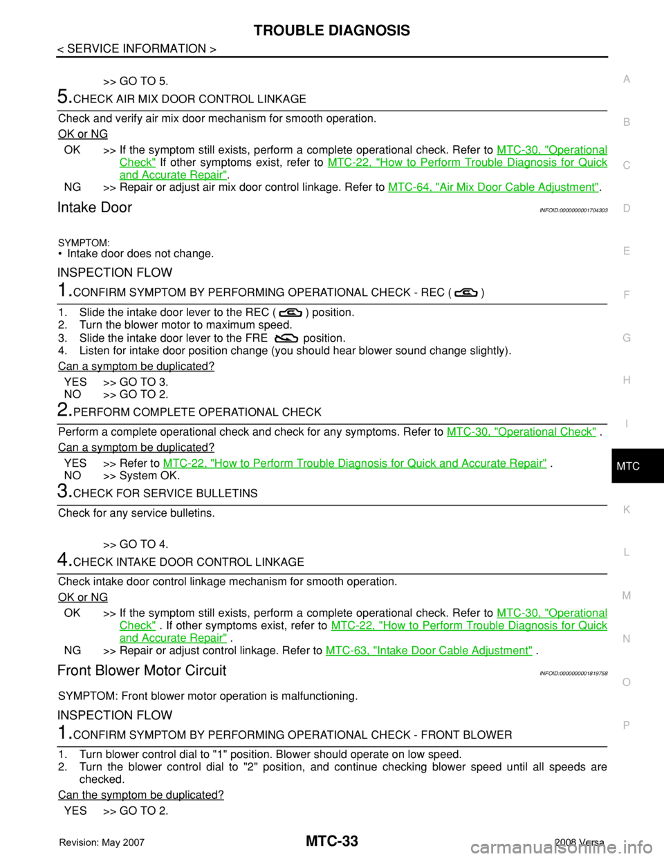
1.CONFIRM SYMPTOM BY PERFORMING OPERATIONAL CHECK - REC ( )
1. Slide the intake door lever to the REC ( ) position.
2. Turn the blower motor to maximum speed.
3. Slide the intake door lever to the FRE position.
4. Listen for intake door position change (you should hear blower sound change slightly).
Can a symptom be duplicated?
YES >> GO TO 3.
NO >> GO TO 2.
2.PERFORM COMPLETE OPERATIONAL CHECK
Perform a complete operational check and check for any symptoms. Refer to MTC-30, "
Operational Check" .
Can a symptom be duplicated?
YES >> Refer to MTC-22, "How to Perform Trouble Diagnosis for Quick and Accurate Repair" .
NO >> System OK.
3.CHECK FOR SERVICE BULLETINS
Check for any service bulletins.
>> GO TO 4.
4.CHECK INTAKE DOOR CONTROL LINKAGE
Check intake door control linkage mechanism for smooth operation.
OK or NG
OK >> If the symptom still exists, perform a complete operational check. Refer to MTC-30, "Operational
Check" . If other symptoms exist, refer to MTC-22, "How to Perform Trouble Diagnosis for Quick
and Accurate Repair" .
NG >> Repair or adjust control linkage. Refer to MTC-63, "
Intake Door Cable Adjustment" .
Front Blower Motor CircuitINFOID:0000000001819758
SYMPTOM: Front blower motor operation is malfunctioning.
INSPECTION FLOW
1.CONFIRM SYMPTOM BY PERFORMING OPERATIONAL CHECK - FRONT BLOWER
1. Turn blower control dial to "1" position. Blower should operate on low speed.
2. Turn the blower control dial to "2" position, and continue checking blower speed until all speeds are
checked.
Can the symptom be duplicated?
YES >> GO TO 2.
Page 2372 of 2771
MTC-34
< SERVICE INFORMATION >
TROUBLE DIAGNOSIS
NO >> GO TO 3.
2.PERFORM COMPLETE OPERATIONAL CHECK
Perform a complete operational check and check for any symptoms. Refer to MTC-30, "
Operational Check".
Can a symptom be duplicated?
YES >> Refer to MTC-22, "How to Perform Trouble Diagnosis for Quick and Accurate Repair".
NO >> System OK.
3.CHECK FOR SERVICE BULLETINS
Check for any service bulletins.
>> GO TO 4.
4.CHECK FRONT BLOWER MOTOR CIRCUIT
Check front blower motor circuit. Refer to "DIAGNOSTIC PROCEDURE FOR FRONT BLOWER MOTOR" .
OK or NG?
OK >> If the symptom still exists, perform a complete operational check. Refer to MTC-30, "Operational
Check". If other symptoms exist, refer to MTC-22, "How to Perform Trouble Diagnosis for Quick
and Accurate Repair".
NG >> Repair as necessary.
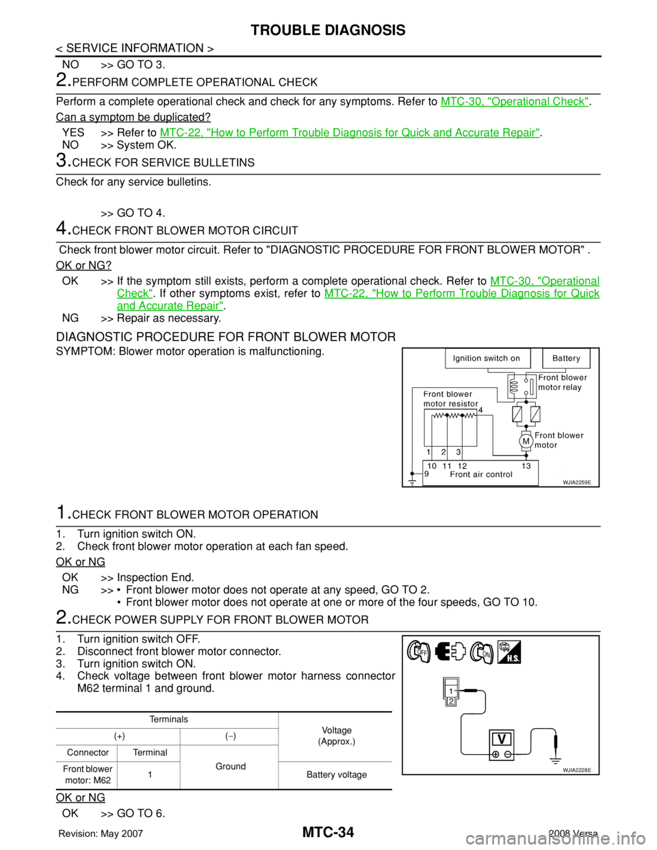
DIAGNOSTIC PROCEDURE FOR FRONT BLOWER MOTOR
SYMPTOM: Blower motor operation is malfunctioning.
1.CHECK FRONT BLOWER MOTOR OPERATION
1. Turn ignition switch ON.
2. Check front blower motor operation at each fan speed.
OK or NG
OK >> Inspection End.
NG >> • Front blower motor does not operate at any speed, GO TO 2.
• Front blower motor does not operate at one or more of the four speeds, GO TO 10.
2.CHECK POWER SUPPLY FOR FRONT BLOWER MOTOR
1. Turn ignition switch OFF.
2. Disconnect front blower motor connector.
3. Turn ignition switch ON.
4. Check voltage between front blower motor harness connector
M62 terminal 1 and ground.
OK or NG
OK >> GO TO 6.
WJIA2259E
Te r m i n a l s
Vo l ta g e
(Approx.) (+) (−)
Connector Terminal
Ground
Front blower
motor: M621 Battery voltage
WJIA2228E
Page 2373 of 2771
![NISSAN TIIDA 2008 Service Repair Manual TROUBLE DIAGNOSIS
MTC-35
< SERVICE INFORMATION >
C
D
E
F
G
H
I
K
L
MA
B
MTC
N
O
P
NG >> Check power supply circuit and 15A fuses [Nos. 15 and 17, located in the fuse block (J/B)].
Refer to PG-3, " NISSAN TIIDA 2008 Service Repair Manual TROUBLE DIAGNOSIS
MTC-35
< SERVICE INFORMATION >
C
D
E
F
G
H
I
K
L
MA
B
MTC
N
O
P
NG >> Check power supply circuit and 15A fuses [Nos. 15 and 17, located in the fuse block (J/B)].
Refer to PG-3, "](/manual-img/5/57399/w960_57399-2372.png)
TROUBLE DIAGNOSIS
MTC-35
< SERVICE INFORMATION >
C
D
E
F
G
H
I
K
L
MA
B
MTC
N
O
P
NG >> Check power supply circuit and 15A fuses [Nos. 15 and 17, located in the fuse block (J/B)].
Refer to PG-3, "
Schematic".
• If fuses are OK, reinstall fuses and GO TO 3.
• If fuses are NG, replace fuse and check harness for short circuit. Repair or replace if necessary.
3.CHECK BLOWER MOTOR RELAY POWER SUPPLY CIRCUITS
1. Turn ignition switch OFF.
2. Disconnect blower motor relay connector.
3. Turn ignition switch ON.
4. Check voltage between blower motor relay harness connector J-
1 terminal 1, 5 and ground.
OK or NG
OK >> GO TO 4.
NG >> Repair harness or connector.
4.CHECK BLOWER MOTOR RELAY (SWITCH SIDE) CIRCUIT FOR OPEN
1. Turn ignition switch OFF.
2. Check continuity between blower motor relay harness connector
J-1 (A) terminal 3 and front blower motor harness connector
M62 (B) terminal 1.
OK or NG
OK >> GO TO 5.
NG >> Repair harness or connector.
5.CHECK BLOWER MOTOR RELAY GROUND CIRCUIT
Check continuity between blower motor relay harness connector J-1
terminal 2 and ground.
OK or NG
OK >> Replace blower motor relay.
NG >> Repair harness or connector.
6.CHECK FRONT BLOWER MOTOR
Check continuity between front blower motor terminals 1 and 2.
NOTE:
Ensure that there are no foreign particles inside the A/C unit assem-
bly for a smooth rotation of the front blower motor.
OK or NG
OK >> GO TO 7.
NG >> Replace front blower motor. Refer to MTC-62, "
Removal
and Installation".
7.CHECK CIRCUIT CONTINUITY BETWEEN FRONT BLOWER MOTOR AND FRONT AIR CONTROL 1 - Ground Battery voltage should exist.
5 - Ground Battery voltage should exist.
WJIA1783E
Continuity should exist.
WJIA2263E
Continuity should exist.
WJIA2264E
1 - 2 : Continuity should exist.
WJIA2230E
Page 2374 of 2771
MTC-36
< SERVICE INFORMATION >
TROUBLE DIAGNOSIS
1. Disconnect front air control connector.
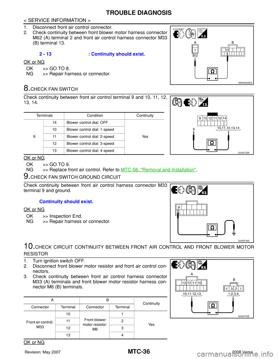
2. Check continuity between front blower motor harness connector
M62 (A) terminal 2 and front air control harness connector M33
(B) terminal 13.
OK or NG
OK >> GO TO 8.
NG >> Repair harness or connector.
8.CHECK FAN SWITCH
Check continuity between front air control terminal 9 and 10, 11, 12,
13, 14.
OK or NG
OK >> GO TO 9.
NG >> Replace front air control. Refer to MTC-58, "
Removal and Installation".
9.CHECK FAN SWITCH GROUND CIRCUIT
Check continuity between front air control harness connector M33
terminal 9 and ground.
OK or NG
OK >> Inspection End.
NG >> Repair harness or connector.
10.CHECK CIRCUIT CONTINUITY BETWEEN FRONT AIR CONTROL AND FRONT BLOWER MOTOR
RESISTOR
1. Turn ignition switch OFF.
2. Disconnect front blower motor resistor and front air control con-
nectors.
3. Check continuity between front air control harness connector
M33 (A) terminals and front blower motor resistor harness con-
nector M6 (B) terminals.
OK or NG
2 - 13 : Continuity should exist.
AWIIA0339ZZ
Terminals Condition Continuity
914 Blower control dial: OFF
Ye s 10 Blower control dial: 1-speed
11 Blower control dial: 2-speed
12 Blower control dial: 3-speed
13 Blower control dial: 4-speed
SJIA0732E
Continuity should exist.
SJIA0734E
AB
Continuity
Connector Terminal Connector Terminal
Front air control:
M3310
Front blower
motor resistor:
M61
Ye s 11 2
12 3
13 4
SJIA0733E
Page 2375 of 2771
TROUBLE DIAGNOSIS
MTC-37
< SERVICE INFORMATION >
C
D
E
F
G
H
I
K
L
MA
B
MTC
N
O
P
OK >> GO TO 11.
NG >> Repair harness or connector.
11 .CHECK FAN SWITCH
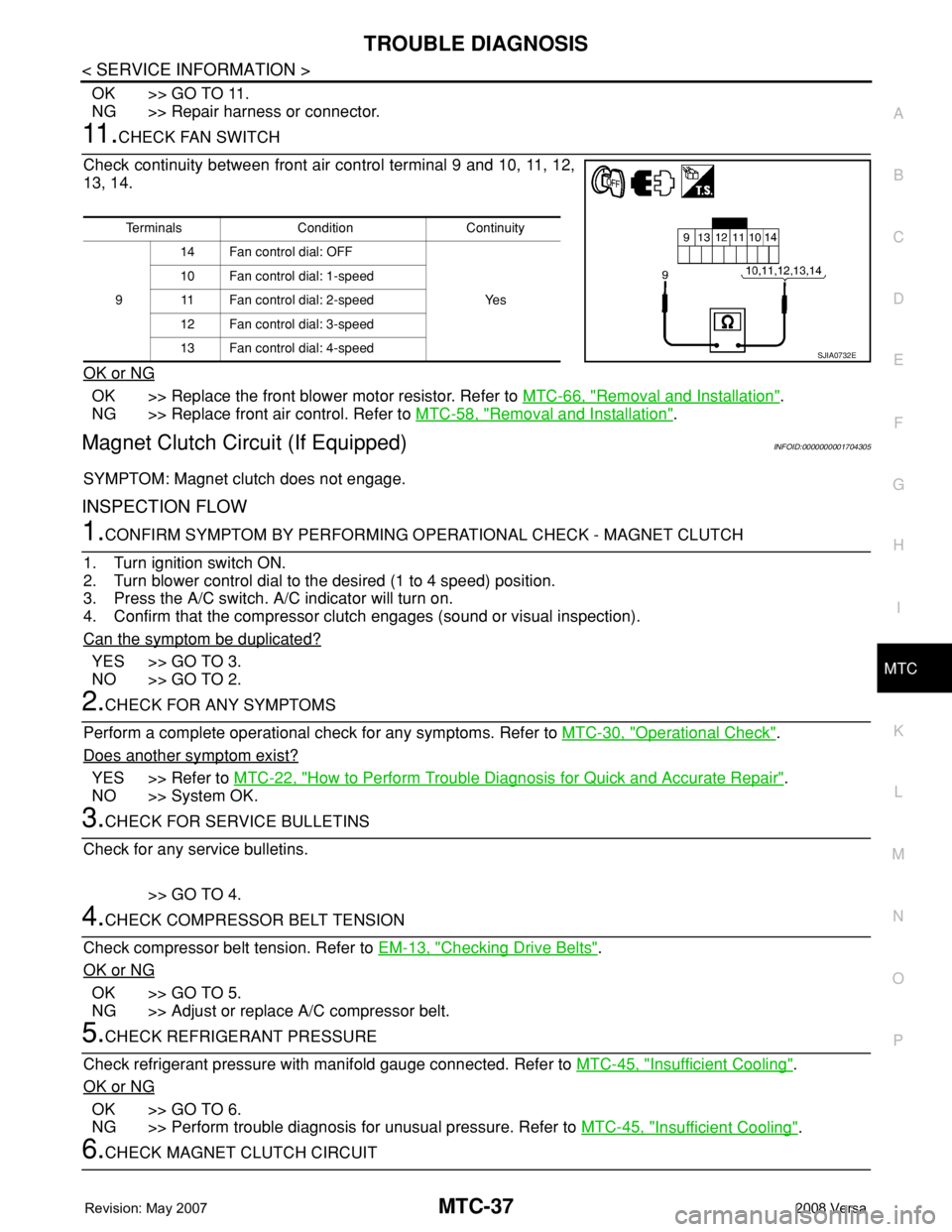
Check continuity between front air control terminal 9 and 10, 11, 12,
13, 14.
OK or NG
OK >> Replace the front blower motor resistor. Refer to MTC-66, "Removal and Installation".
NG >> Replace front air control. Refer to MTC-58, "
Removal and Installation".
Magnet Clutch Circuit (If Equipped)INFOID:0000000001704305
SYMPTOM: Magnet clutch does not engage.
INSPECTION FLOW
1.CONFIRM SYMPTOM BY PERFORMING OPERATIONAL CHECK - MAGNET CLUTCH
1. Turn ignition switch ON.
2. Turn blower control dial to the desired (1 to 4 speed) position.
3. Press the A/C switch. A/C indicator will turn on.
4. Confirm that the compressor clutch engages (sound or visual inspection).
Can the symptom be duplicated?
YES >> GO TO 3.
NO >> GO TO 2.
2.CHECK FOR ANY SYMPTOMS
Perform a complete operational check for any symptoms. Refer to MTC-30, "
Operational Check".
Does another symptom exist?
YES >> Refer to MTC-22, "How to Perform Trouble Diagnosis for Quick and Accurate Repair".
NO >> System OK.
3.CHECK FOR SERVICE BULLETINS
Check for any service bulletins.
>> GO TO 4.
4.CHECK COMPRESSOR BELT TENSION
Check compressor belt tension. Refer to EM-13, "
Checking Drive Belts".
OK or NG
OK >> GO TO 5.
NG >> Adjust or replace A/C compressor belt.
5.CHECK REFRIGERANT PRESSURE
Check refrigerant pressure with manifold gauge connected. Refer to MTC-45, "
Insufficient Cooling".
OK or NG
OK >> GO TO 6.
NG >> Perform trouble diagnosis for unusual pressure. Refer to MTC-45, "
Insufficient Cooling".
6.CHECK MAGNET CLUTCH CIRCUIT
Terminals Condition Continuity
914 Fan control dial: OFF
Ye s 10 Fan control dial: 1-speed
11 Fan control dial: 2-speed
12 Fan control dial: 3-speed
13 Fan control dial: 4-speed
SJIA0732E
Page 2386 of 2771
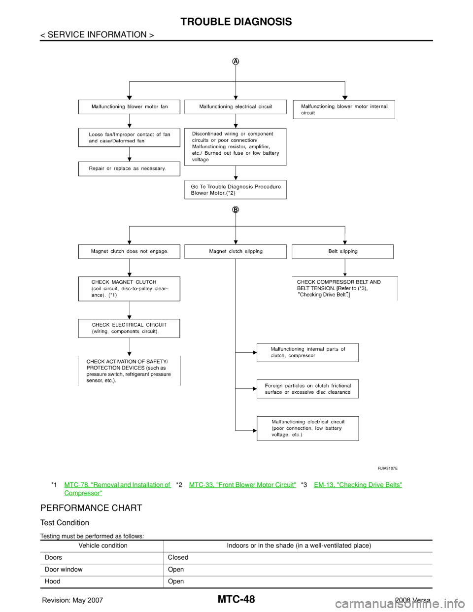
MTC-48
< SERVICE INFORMATION >
TROUBLE DIAGNOSIS
PERFORMANCE CHART
Test Condition
Testing must be performed as follows:
*1MTC-78, "Removal and Installation of
Compressor"
*2MTC-33, "Front Blower Motor Circuit"*3EM-13, "Checking Drive Belts"
RJIA3107E
Vehicle condition Indoors or in the shade (in a well-ventilated place)
Doors Closed
Door window Open
Hood Open
Page 2389 of 2771
TROUBLE DIAGNOSIS
MTC-51
< SERVICE INFORMATION >
C
D
E
F
G
H
I
K
L
MA
B
MTC
N
O
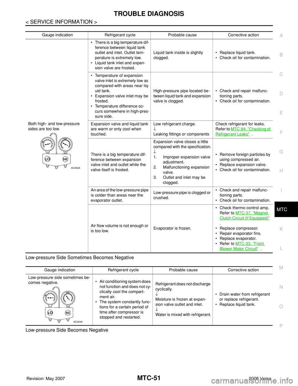
P Low-pressure Side Sometimes Becomes Negative
Low-pressure Side Becomes Negative
Gauge indication Refrigerant cycle Probable cause Corrective action
Both high- and low-pressure
sides are too low.• There is a big temperature dif-
ference between liquid tank
outlet and inlet. Outlet tem-
perature is extremely low.
• Liquid tank inlet and expan-
sion valve are frosted.Liquid tank inside is slightly
clogged.• Replace liquid tank.
• Check oil for contamination.
• Temperature of expansion
valve inlet is extremely low as
compared with areas near liq-
uid tank.
• Expansion valve inlet may be
frosted.
• Temperature difference oc-
curs somewhere in high-pres-
sure side.High-pressure pipe located be-
tween liquid tank and expansion
valve is clogged.• Check and repair malfunc-
tioning parts.
• Check oil for contamination.
Expansion valve and liquid tank
are warm or only cool when
touched.Low refrigerant charge.
↓
Leaking fittings or componentsCheck refrigerant for leaks.
Refer to MTC-84, "
Checking of
Refrigerant Leaks" .
There is a big temperature dif-
ference between expansion
valve inlet and outlet while the
valve itself is frosted.Expansion valve closes a little
compared with the specification.
↓
1. Improper expansion valve
adjustment.
2. Malfunctioning expansion
valve.
3. Outlet and inlet may be
clogged.• Remove foreign particles by
using compressed air.
• Replace expansion valve.
• Check oil for contamination.
An area of the low-pressure pipe
is colder than areas near the
evaporator outlet.Low-pressure pipe is clogged or
crushed.• Check and repair malfunc-
tioning parts.
• Check oil for contamination.
Air flow volume is not enough or
is too low.Evaporator is frozen.• Check thermo control amp.
Refer to MTC-37, "
Magnet
Clutch Circuit (If Equipped)"
.
• Replace compressor.
• Repair evaporator fins.
• Replace evaporator.
• Refer to MTC-33, "
Front
Blower Motor Circuit" .
AC353A
Gauge indication Refrigerant cycle Probable cause Corrective action
Low-pressure side sometimes be-
comes negative.• Air conditioning system does
not function and does not cy-
clically cool the compart-
ment air.
• The system constantly func-
tions for a certain period of
time after compressor is
stopped and restarted.Refrigerant does not discharge
cyclically.
↓
Moisture is frozen at expan-
sion valve outlet and inlet.
↓
Water is mixed with refrigerant.• Drain water from refrigerant
or replace refrigerant.
• Replace liquid tank.
AC354A
Page 2398 of 2771
MTC-60
< SERVICE INFORMATION >
A/C UNIT ASSEMBLY
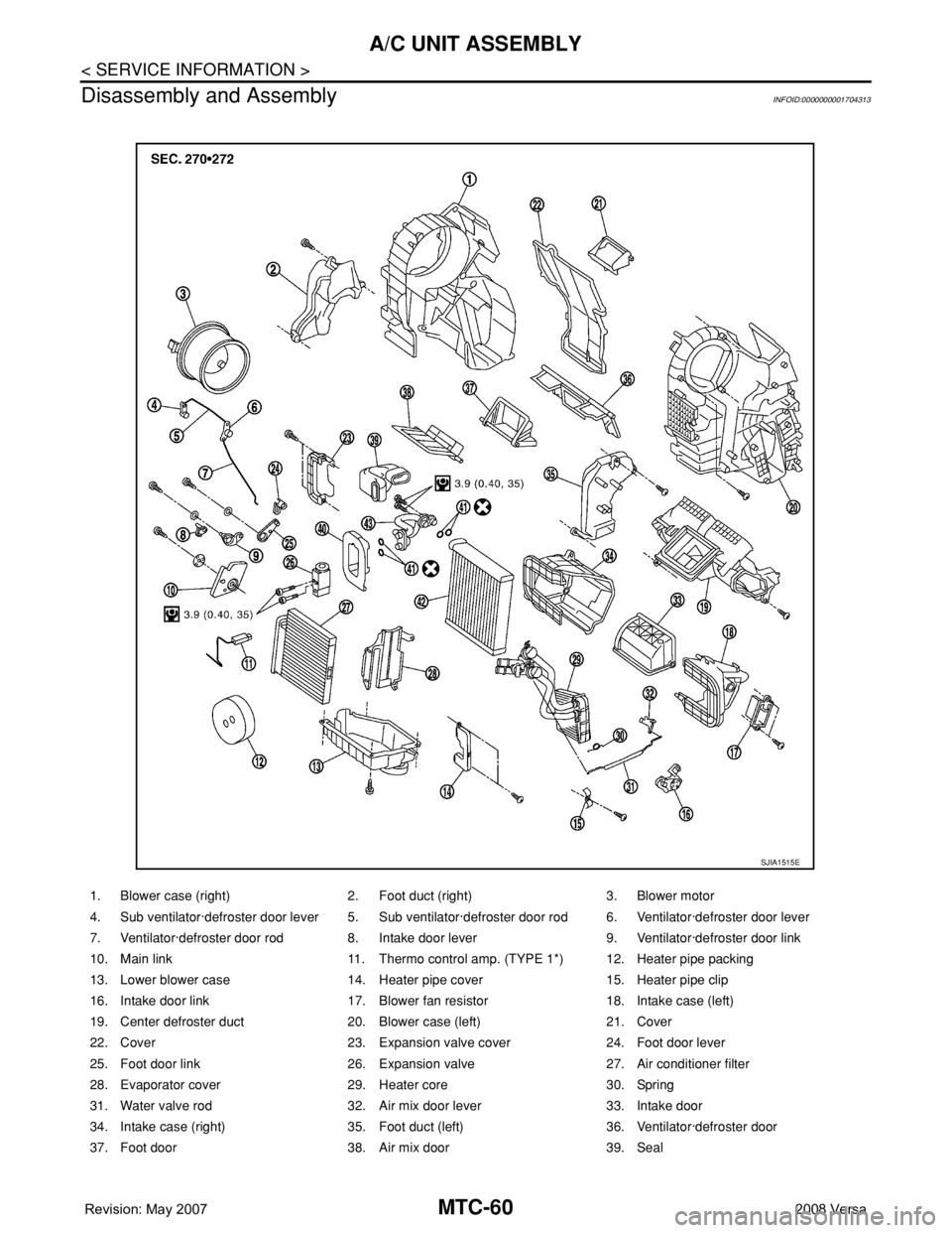
Disassembly and Assembly
INFOID:0000000001704313
1. Blower case (right) 2. Foot duct (right) 3. Blower motor
4. Sub ventilator·defroster door lever 5. Sub ventilator·defroster door rod 6. Ventilator·defroster door lever
7. Ventilator·defroster door rod 8. Intake door lever 9. Ventilator·defroster door link
10. Main link 11. Thermo control amp. (TYPE 1*) 12. Heater pipe packing
13. Lower blower case 14. Heater pipe cover 15. Heater pipe clip
16. Intake door link 17. Blower fan resistor 18. Intake case (left)
19. Center defroster duct 20. Blower case (left) 21. Cover
22. Cover 23. Expansion valve cover 24. Foot door lever
25. Foot door link 26. Expansion valve 27. Air conditioner filter
28. Evaporator cover 29. Heater core 30. Spring
31. Water valve rod 32. Air mix door lever 33. Intake door
34. Intake case (right) 35. Foot duct (left) 36. Ventilator·defroster door
37. Foot door 38. Air mix door 39. Seal
SJIA1515E