2008 NISSAN TIIDA Engine mechanical
[x] Cancel search: Engine mechanicalPage 136 of 2771

AT-124
< SERVICE INFORMATION >
DTC P0744 A/T TCC S/V FUNCTION (LOCK-UP)
DTC P0744 A/T TCC S/V FUNCTION (LOCK-UP)
DescriptionINFOID:0000000001703260
• This malfunction will not be detected while the OD OFF indicator lamp is indicating another self-diagnosis
malfunction.
• This malfunction is detected when the A/T does not shift into fourth gear position or the torque converter
clutch does not lock-up as instructed by the TCM. This is not caused by electrical malfunction (circuits open
or shorted) but by mechanical malfunction such as control valve sticking, improper solenoid valve operation,
malfunctioning oil pump or torque converter clutch, etc.
CONSULT-III Reference Value in Data Monitor ModeINFOID:0000000001703261
Remarks: Specification data are reference values.
On Board Diagnosis LogicINFOID:0000000001703262
• This is an OBD-II self-diagnostic item.
• Diagnostic trouble code “P0744 A/T TCC S/V FNCTN” with CONSULT-III is detected when A/T cannot per-
form lock-up even if electrical circuit is good.
• This diagnosis monitors actual gear position by checking the torque converter slip ratio calculated by TCM
as follows:
Torque converter slip ratio = A x C/B
A: Output shaft revolution signal from revolution sensor
B: Engine speed signal from ECM
C: Gear ratio determined as gear position which TCM supposes
If the actual gear position is much lower than the position (4th) supposed by TCM, the slip ratio will be much
less than normal. In case the ratio does not reach the specified value, TCM judges this diagnosis malfunc-
tion.
This malfunction will be caused when shift solenoid valve B is stuck closed.
• Gear positions supposed by TCM are as follows.
In case of gear position with no malfunctions: 1, 2, 3 and 4 positions
In case of gear position with shift solenoid valve B stuck closed: 1, 2, 2 and 1* positions to each gear position
above
*: “P0744 A/T TCC S/V FNCTN” is detected.
Possible CauseINFOID:0000000001703263
• Line pressure solenoid valve
• Torque converter clutch solenoid valve
• Each clutch
• Hydraulic control circuit
DTC Confirmation ProcedureINFOID:0000000001703264
CAUTION:
• Always drive vehicle at a safe speed.
• If performing this “DTC Confirmation Procedure” again, always turn ignition switch OFF and wait at
least 10 seconds before continuing.
After the repair, perform the following procedure to confirm the malfunction is eliminated.
WITH CONSULT-III
1. Start engine and select “DATA MONITOR” mode for “A/T” with CONSULT-III.
2. Touch “START”.
3. Make sure that output voltage of A/T fluid temperature sensor is within the range below.
FLUID TEMP SE: 0.4 - 1.5 V
If out of range, drive vehicle to decrease voltage (warm up the fluid) or stop engine to increase voltage
(cool down the fluid).
4. Select “TCC S/V FNCTN P0744” of “DTC WORK SUPPORT” mode for “A/T” with CONSULT-III and touch
“START”.
Item name Condition Display value (Approx)
TCC S/V DUTY Lock-up OFF ⇔ Lock-up ON 4% ⇔ 94%
Page 510 of 2771

BL-76
< SERVICE INFORMATION >
INTELLIGENT KEY SYSTEM
System Description
INFOID:0000000001703999
• The Intelligent Key system is a system that makes it possible to lock and unlock the door locks (door lock/
unlock function), and start the engine (engine start function) by carrying around the Intelligent Key (without
some key operation), which operates based on the results of electronic ID verification using two-way com-
munications between the Intelligent Key and the vehicle (Intelligent Key unit).
• Vehicles equipped with a manual transmission include a key interlock solenoid located in the steering col-
umn to prevent accidental shut-off of the ignition switch and locking of the steering wheel during driving con-
dition when the vehicle is moving.
CAUTION:
The driver should always carry the Intelligent Key
• Operation of the remote controller buttons on the Intelligent Key also provides the same functions as the
remote control entry system. (Remote keyless entry functions)
• If an action that does not meet the operating conditions of the Intelligent Key system is taken, the buzzer
goes off to inform the driver. (Warning chime functions)
• When a door lock is locked or unlocked with request switch or remote controller button operation, the hazard
lamps flash and the buzzer (outside vehicle) sounds (Hazard and buzzer reminder function).
• Even if the Intelligent Key battery is completely discharged, the door locks can be locked and unlocked and
the engine started with the mechanical key built into the Intelligent Key.
• The settings for each function can be changed with the CONSULT-III.
• If an Intelligent Key is lost, a new Intelligent Key can be registered. A maximum of 4 Intelligent Keys can be
registered.
• It has been made possible to diagnose the system and register an Intelligent Key with the CONSULT-III.
DOOR LOCK/UNLOCK FUNCTION
Only when pressing the request switch, it is possible to lock and unlock the door by carrying around the Intelli-
gent Key (without some key operation).
System Diagram
Operation Description
• When the Intelligent Key unit detects that each request switch is pressed, it starts the outside key antenna
and inside key antenna corresponding to the pressed request switch and sends the request signal to the
Intelligent Key. And then, make sure that the Intelligent Key is near door.
• If the Intelligent Key is within the outside key antenna detection area, it receives the request signal and
sends the key ID signal to the Intelligent Key unit.
• Intelligent Key unit receives the key ID signal and compares it with the registered key ID.
• If the key ID check result is OK, the Intelligent Key unit sends the door lock/unlock request signal to BCM
(Body control module) via CAN communication line.
• Intelligent Key unit sends the door lock/unlock signal and sounds Intelligent Key warning buzzer (lock: 2
times, unlock: 1 time) at the same time.
• When BCM receives the door lock/unlock signal, it operates door lock actuator and flashes the hazard warn-
ing lamp (lock: 2 times, unlock: 1 time) at the same time as reminder.
Operation Condition
If the following conditions are not satisfied, door lock/unlock operations are not performed even if the request
switch is operated.
LIIA2926E
Page 515 of 2771

INTELLIGENT KEY SYSTEM
BL-81
< SERVICE INFORMATION >
C
D
E
F
G
H
J
K
L
MA
B
BL
N
O
P
When ignition switch turns to START position, BCM sends starter request signal to IPDM E/R. Then, engine
starts.
Even if Intelligent Key battery runs down, Intelligent key unit can start engine with mechanical key built Intelli-
gent Key. For details, refer toBL-210
.
All of the originally supplied Intelligent Key IDs (except for key) have been registered in Intelligent Key system.
If requested by the vehicle owner, a maximum of four Intelligent Key IDs can be registered into the Intelligent
Key system components.
List of Operation Related Parts
Parts marked with × are the parts related to operation.
WARNING CHIME/BUZZER/LAMPS FUNCTION
Operation Description
The following warning chime (combination meter), Intelligent Key warning buzzer (front door LH), Intelligent
Key warning buzzer (trunk)
*, warning lamps "KEY" and “P-SHIFT” (with CVT) or "LOCK" (with M/T) are given
to the user as warning information while using the intelligent key system.
• Ignition switch warning chime
• Ignition key warning chime
• OFF position warning chime
• Take away warning chime
• Door lock operation warning chime
• Intelligent key low battery warning
• P position warning (with CVT)
• LOCK position warning (with M/T)
NOTE:
For key-in-ignition warning chime related concerns only, refer to DI-41
.
* :
Sedan
Operation Condition
Engine start functions
Intelligent Key
Key switch
Ignition knob switch
Inside key antenna
Intelligent Key unit
CAN communication system
BCM
Combination meter
IPDM E/R
NATS antenna amp.
Steering lock solenoid
Engine start function by the Intelligent Key××××××××× ×
Engine start function by the mechanical key× ××× ×××
Operation ConditionWarning chime/buzzer Warning lamp
Chime
(combina-
tion meter)Buzzer(s) KEYLOCK
(M/T)P-SHIFT
(CVT)
Ignition switch warning chime• Mechanical key is out of ignition switch
(Key switch is OFF)
• Ignition switch is in the ACC, OFF or
LOCK position.
[ignition switch is pressed
(ignition knob switch is ON).]
• Driver door is open.activate — — — —
Ignition key warning chime
(When mechanical key is used)• Mechanical key is inserted in ignition
switch (key switch is ON).
• Ignition switch is in the ACC, OFF or
LOCK position.
• Driver door is open.activate — — — —
Page 533 of 2771

INTELLIGENT KEY SYSTEM
BL-99
< SERVICE INFORMATION >
C
D
E
F
G
H
J
K
L
MA
B
BL
N
O
P
Terminal and Reference Value for BCMINFOID:0000000001704007
Refer to BCS-11, "Terminal and Reference Value for BCM".
Trouble Diagnosis ProcedureINFOID:0000000001704008
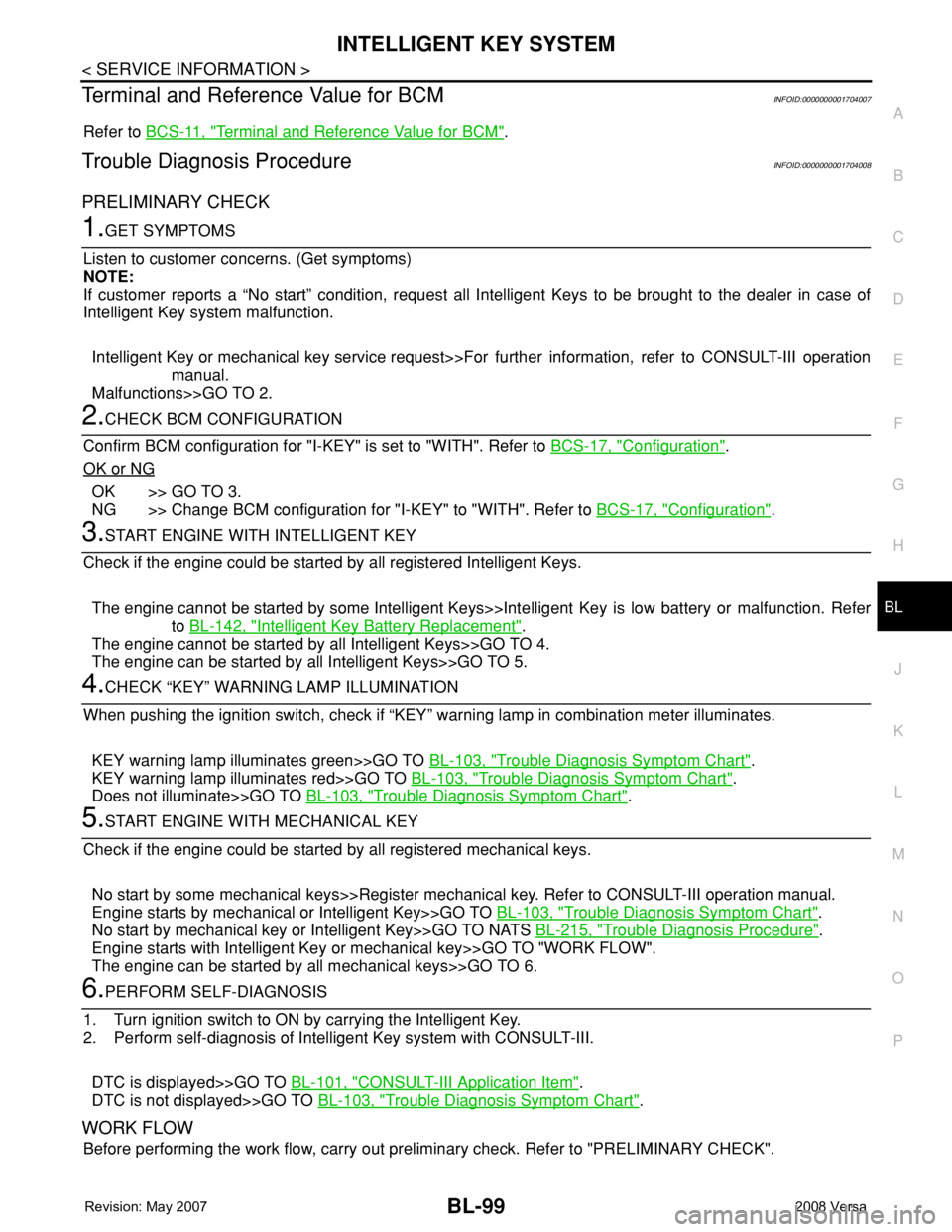
PRELIMINARY CHECK
1.GET SYMPTOMS
Listen to customer concerns. (Get symptoms)
NOTE:
If customer reports a “No start” condition, request all Intelligent Keys to be brought to the dealer in case of
Intelligent Key system malfunction.
Intelligent Key or mechanical key service request>>For further information, refer to CONSULT-III operation
manual.
Malfunctions>>GO TO 2.
2.CHECK BCM CONFIGURATION
Confirm BCM configuration for "I-KEY" is set to "WITH". Refer to BCS-17, "
Configuration".
OK or NG
OK >> GO TO 3.
NG >> Change BCM configuration for "I-KEY" to "WITH". Refer to BCS-17, "
Configuration".
3.START ENGINE WITH INTELLIGENT KEY
Check if the engine could be started by all registered Intelligent Keys.
The engine cannot be started by some Intelligent Keys>>Intelligent Key is low battery or malfunction. Refer
to BL-142, "
Intelligent Key Battery Replacement".
The engine cannot be started by all Intelligent Keys>>GO TO 4.
The engine can be started by all Intelligent Keys>>GO TO 5.
4.CHECK “KEY” WARNING LAMP ILLUMINATION
When pushing the ignition switch, check if “KEY” warning lamp in combination meter illuminates.
KEY warning lamp illuminates green>>GO TO BL-103, "
Trouble Diagnosis Symptom Chart".
KEY warning lamp illuminates red>>GO TO BL-103, "
Trouble Diagnosis Symptom Chart".
Does not illuminate>>GO TO BL-103, "
Trouble Diagnosis Symptom Chart".
5.START ENGINE WITH MECHANICAL KEY
Check if the engine could be started by all registered mechanical keys.
No start by some mechanical keys>>Register mechanical key. Refer to CONSULT-III operation manual.
Engine starts by mechanical or Intelligent Key>>GO TO BL-103, "
Trouble Diagnosis Symptom Chart".
No start by mechanical key or Intelligent Key>>GO TO NATS BL-215, "
Trouble Diagnosis Procedure".
Engine starts with Intelligent Key or mechanical key>>GO TO "WORK FLOW".
The engine can be started by all mechanical keys>>GO TO 6.
6.PERFORM SELF-DIAGNOSIS
1. Turn ignition switch to ON by carrying the Intelligent Key.
2. Perform self-diagnosis of Intelligent Key system with CONSULT-III.
DTC is displayed>>GO TO BL-101, "
CONSULT-III Application Item".
DTC is not displayed>>GO TO BL-103, "
Trouble Diagnosis Symptom Chart".
WORK FLOW
Before performing the work flow, carry out preliminary check. Refer to "PRELIMINARY CHECK".
Page 538 of 2771

BL-104
< SERVICE INFORMATION >
INTELLIGENT KEY SYSTEM
• Key is not inserted in ignition switch.
• One or more registered Intelligent Keys are in the vehicle.
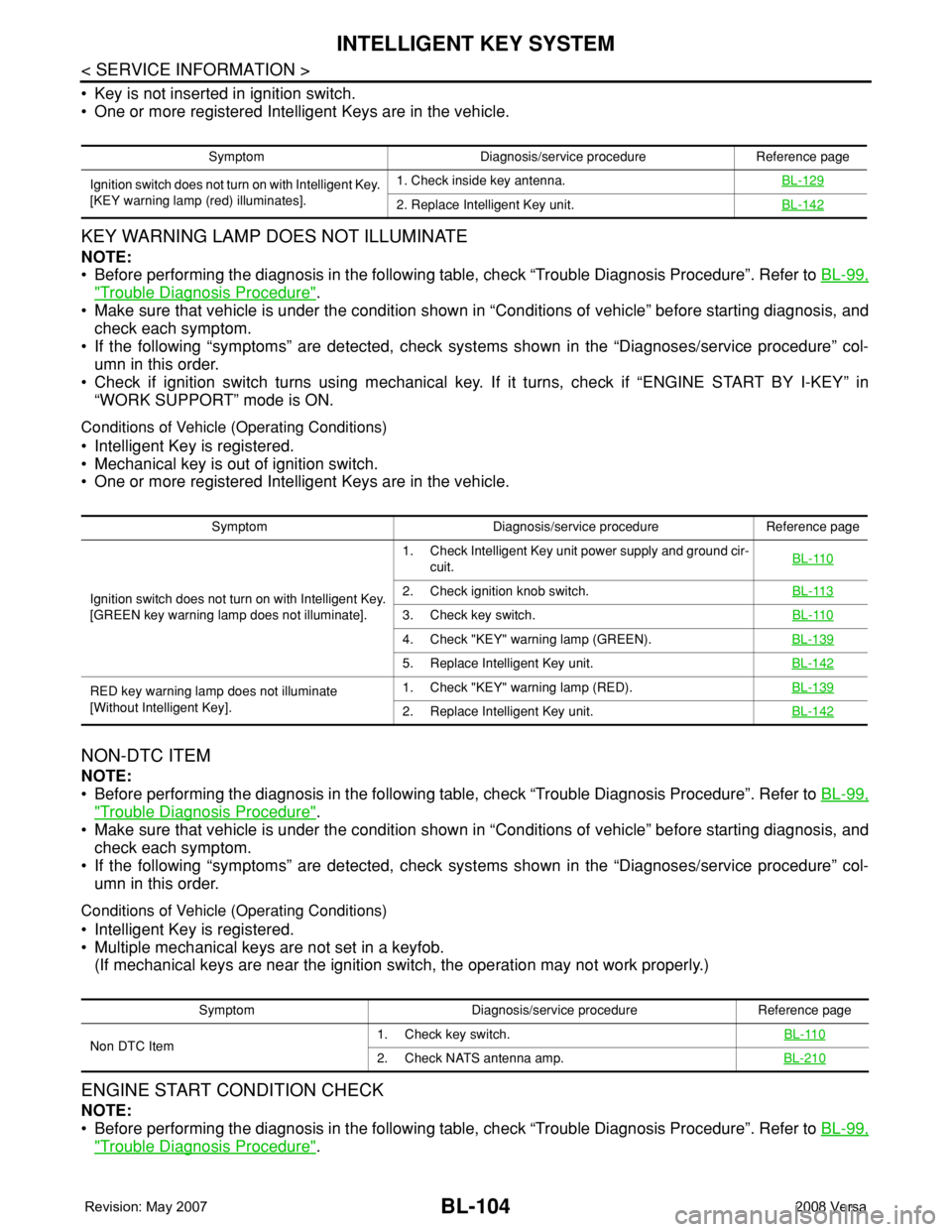
KEY WARNING LAMP DOES NOT ILLUMINATE
NOTE:
• Before performing the diagnosis in the following table, check “Trouble Diagnosis Procedure”. Refer to BL-99,
"Trouble Diagnosis Procedure".
• Make sure that vehicle is under the condition shown in “Conditions of vehicle” before starting diagnosis, and
check each symptom.
• If the following “symptoms” are detected, check systems shown in the “Diagnoses/service procedure” col-
umn in this order.
• Check if ignition switch turns using mechanical key. If it turns, check if “ENGINE START BY I-KEY” in
“WORK SUPPORT” mode is ON.
Conditions of Vehicle (Operating Conditions)
• Intelligent Key is registered.
• Mechanical key is out of ignition switch.
• One or more registered Intelligent Keys are in the vehicle.
NON-DTC ITEM
NOTE:
• Before performing the diagnosis in the following table, check “Trouble Diagnosis Procedure”. Refer to BL-99,
"Trouble Diagnosis Procedure".
• Make sure that vehicle is under the condition shown in “Conditions of vehicle” before starting diagnosis, and
check each symptom.
• If the following “symptoms” are detected, check systems shown in the “Diagnoses/service procedure” col-
umn in this order.
Conditions of Vehicle (Operating Conditions)
• Intelligent Key is registered.
• Multiple mechanical keys are not set in a keyfob.
(If mechanical keys are near the ignition switch, the operation may not work properly.)
ENGINE START CONDITION CHECK
NOTE:
• Before performing the diagnosis in the following table, check “Trouble Diagnosis Procedure”. Refer to BL-99,
"Trouble Diagnosis Procedure".
Symptom Diagnosis/service procedure Reference page
Ignition switch does not turn on with Intelligent Key.
[KEY warning lamp (red) illuminates].1. Check inside key antenna.BL-129
2. Replace Intelligent Key unit.BL-142
Symptom Diagnosis/service procedure Reference page
Ignition switch does not turn on with Intelligent Key.
[GREEN key warning lamp does not illuminate].1. Check Intelligent Key unit power supply and ground cir-
cuit.BL-110
2. Check ignition knob switch.BL-113
3. Check key switch.BL-110
4. Check "KEY" warning lamp (GREEN).BL-139
5. Replace Intelligent Key unit.BL-142
RED key warning lamp does not illuminate
[Without Intelligent Key].1. Check "KEY" warning lamp (RED).BL-139
2. Replace Intelligent Key unit.BL-142
Symptom Diagnosis/service procedure Reference page
Non DTC Item1. Check key switch.BL-110
2. Check NATS antenna amp.BL-210
Page 539 of 2771

INTELLIGENT KEY SYSTEM
BL-105
< SERVICE INFORMATION >
C
D
E
F
G
H
J
K
L
MA
B
BL
N
O
P
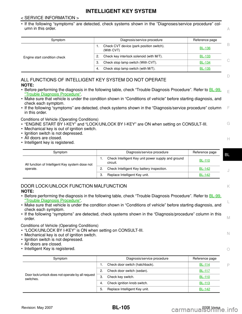
• If the following “symptoms” are detected, check systems shown in the ”Diagnoses/service procedure” col-
umn in this order.
ALL FUNCTIONS OF INTELLIGENT KEY SYSTEM DO NOT OPERATE
NOTE:
• Before performing the diagnosis in the following table, check “Trouble Diagnosis Procedure”. Refer to BL-99,
"Trouble Diagnosis Procedure".
• Make sure that vehicle is under the condition shown in “Conditions of vehicle” before starting diagnosis, and
check each symptom.
• If the following “symptoms” are detected, check systems shown in the “Diagnosis/service procedure” column
in this order.
Conditions of Vehicle (Operating Conditions)
• “ENGINE START BY I-KEY” and “LOCK/UNLOCK BY I-KEY” are ON when setting on CONSULT-III.
• Mechanical key is out of ignition switch.
• Ignition switch is not depressed.
• All doors are closed.
• Intelligent key is registered.
DOOR LOCK/UNLOCK FUNCTION MALFUNCTION
NOTE:
• Before performing the diagnosis in the following table, check “Trouble Diagnosis Procedure”. Refer to BL-99,
"Trouble Diagnosis Procedure".
• Make sure that vehicle is under the condition shown in “Conditions of vehicle” before starting diagnosis, and
check each symptom.
• If the following “symptoms” are detected, check systems shown in the “Diagnosis/procedure” column in this
order.
Conditions of Vehicle (Operating Conditions)
• “LOCK/UNLOCK BY I-KEY” is ON when setting on CONSULT-III.
• Mechanical key is out of ignition switch.
• Ignition switch is not depressed.
• All doors are closed.
• Intelligent Key is registered.
Symptom Diagnosis/service procedure Reference page
Engine start condition check1. Check CVT device (park position switch).
(With CVT)BL-136
2. Check key interlock solenoid (with M/T).BL-133
3. Check stop lamp switch (With CVT).BL-134
4. Check stop lamp switch (with M/T).BL-135
Symptom Diagnosis/service procedure Reference page
All function of Intelligent Key system dose not
operate.1. Check Intelligent Key unit power supply and ground
circuit.BL-110
2. Check Intelligent Key battery inspection.BL-142
3. Replace Intelligent Key unit.BL-142
Symptom Diagnosis/service procedure Reference page
Door lock/unlock does not operate by all request
switches.1. Check door switch (hatchback).BL-114
2. Check door switch (sedan).BL-117
3. Check key switch.BL-110
4. Check ignition knob switch.BL-113
5. Replace Intelligent Key unit.BL-142
Page 644 of 2771

BL-210
< SERVICE INFORMATION >
NATS (NISSAN ANTI-THEFT SYSTEM)
NATS (NISSAN ANTI-THEFT SYSTEM)
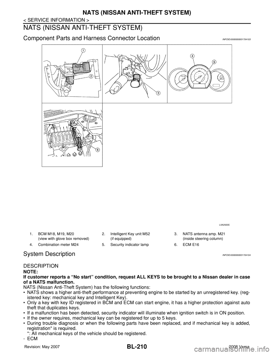
Component Parts and Harness Connector LocationINFOID:0000000001704103
System DescriptionINFOID:0000000001704104
DESCRIPTION
NOTE:
If customer reports a “No start” condition, request ALL KEYS to be brought to a Nissan dealer in case
of a NATS malfunction.
NATS (Nissan Anti-Theft System) has the following functions:
• NATS shows a higher anti-theft performance at preventing engine to be started by an unregistered key. (reg-
istered key: mechanical key and Intelligent Key).
• Only a key with key ID registered in BCM and ECM can start engine, it has a higher protection against auto
theft that duplicates keys.
• If a malfunction has been detected, security indicator will illuminate when ignition switch is in ON position.
• If the owner requires, mechanical key can be registered for up to 5 keys.
• During trouble diagnosis or when the following parts have been replaced, and if mechanical key is added,
registration* is required.
*: All mechanical keys of the vehicle should be registered.
-ECM
LIIA2920E
1. BCM M18, M19, M20
(view with glove box removed)2. Intelligent Key unit M52
(if equipped)3. NATS antenna amp. M21
(inside steering column)
4. Combination meter M24 5. Security indicator lamp 6. ECM E16
Page 645 of 2771

NATS (NISSAN ANTI-THEFT SYSTEM)
BL-211
< SERVICE INFORMATION >
C
D
E
F
G
H
J
K
L
MA
B
BL
N
O
P
-BCM
- Mechanical key
• NATS trouble diagnoses, system initialization and additional registration of other NATS mechanical key IDs
must be carried out using CONSULT-III hardware and CONSULT-III NATS software. When NATS initializa-
tion has been completed, the ID of the inserted mechanical key can be displayed.
Regarding the procedures of NATS initialization and mechanical key ID registration, refer to CONSULT-III
operation manual NATS.
SECURITY INDICATOR
• Forewarns that the vehicle is equipped with NATS.
• Security indicator will not blink while the ignition knob is in ON or START state.
NOTE:
Because security indicator is highly efficient, the battery is barely affected.
Condition of Security Indicator
• When operating the ignition switch with Intelligent Key, security indicator lamp will turn off at once if ignition
switch is pressed and blinks when ignition switch is released.
• When operating the ignition switch with mechanical key security indicator will turn off at once if mechanical
key is inserted into key cylinder and blinks when mechanical key is removed.
(Once the mechanical key is inserted into key cylinder, BCM will only perform the key ID verification with
mechanical key)
System CompositionINFOID:0000000001704105
The function of the NATS consists of the following:
• Mechanical key
• NATS antenna amp. located in the ignition key cylinder
•BCM
• ECM (Engine control module)
• Security indicator
• Intelligent Key unit (if equipped)
NOTE:
The communication between ECM, BCM and/or Intelligent Key unit uses the CAN communication sys-
tem.
ECM Re-communicating FunctionINFOID:0000000001704106
Performing the following procedure can automatically perform re-communication of ECM and BCM or Intelli-
gent Key unit, but only when the ECM has been replaced with a new one which has never been energized on-
board.
(In this step, initialization procedure by CONSULT-III is not necessary)
NOTE:
•When registering new Key IDs or replacing the ECM other than brand new, refer to CONSULT-III
Operation Manual NATS.
LIIA2637E