2008 NISSAN TIIDA fuse
[x] Cancel search: fusePage 2344 of 2771

MTC-6
< SERVICE INFORMATION >
PRECAUTIONS
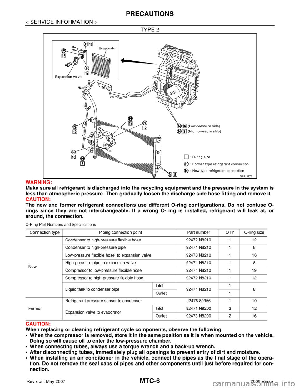
TYPE 2
WARNING:
Make sure all refrigerant is discharged into the recycling equipment and the pressure in the system is
less than atmospheric pressure. Then gradually loosen the discharge side hose fitting and remove it.
CAUTION:
The new and former refrigerant connections use different O-ring configurations. Do not confuse O-
rings since they are not interchangeable. If a wrong O-ring is installed, refrigerant will leak at, or
around, the connection.
O-Ring Part Numbers and Specifications
CAUTION:
When replacing or cleaning refrigerant cycle components, observe the following.
• When the compressor is removed, store it in the same position as it is when mounted on the vehicle.
Doing so will cause oil to enter the low-pressure chamber.
• When connecting tubes, always use a torque wrench and a back-up wrench.
• After disconnecting tubes, immediately plug all openings to prevent entry of dirt and moisture.
• When installing an air conditioner in the vehicle, connect the pipes as the final stage of the opera-
tion. Do not remove the seal caps of pipes and other components until just before required for con-
nection.
SJIA1327E
Connection type Piping connection point Part number QTY O-ring size
NewCondenser to high-pressure flexible hose 92472 N8210 1 12
Condenser to high-pressure pipe 92471 N8210 1 8
Low-pressure flexible hose to expansion valve 92473 N8210 1 16
High-pressure pipe to expansion valve 92471 N8210 1 8
Compressor to low-pressure flexible hose 92474 N8210 1 19
Compressor to high-pressure flexible hose 92472 N8210 1 12
Liquid tank to condenser pipeInlet
92471 N82101
8
Outlet 1
FormerRefrigerant pressure sensor to condenser J2476 89956 1 10
Expansion valve to evaporatorInlet 92471 N8200 2 12
Outlet 92473 N8200 2 16
Page 2373 of 2771
![NISSAN TIIDA 2008 Service Repair Manual TROUBLE DIAGNOSIS
MTC-35
< SERVICE INFORMATION >
C
D
E
F
G
H
I
K
L
MA
B
MTC
N
O
P
NG >> Check power supply circuit and 15A fuses [Nos. 15 and 17, located in the fuse block (J/B)].
Refer to PG-3, " NISSAN TIIDA 2008 Service Repair Manual TROUBLE DIAGNOSIS
MTC-35
< SERVICE INFORMATION >
C
D
E
F
G
H
I
K
L
MA
B
MTC
N
O
P
NG >> Check power supply circuit and 15A fuses [Nos. 15 and 17, located in the fuse block (J/B)].
Refer to PG-3, "](/manual-img/5/57399/w960_57399-2372.png)
TROUBLE DIAGNOSIS
MTC-35
< SERVICE INFORMATION >
C
D
E
F
G
H
I
K
L
MA
B
MTC
N
O
P
NG >> Check power supply circuit and 15A fuses [Nos. 15 and 17, located in the fuse block (J/B)].
Refer to PG-3, "
Schematic".
• If fuses are OK, reinstall fuses and GO TO 3.
• If fuses are NG, replace fuse and check harness for short circuit. Repair or replace if necessary.
3.CHECK BLOWER MOTOR RELAY POWER SUPPLY CIRCUITS
1. Turn ignition switch OFF.
2. Disconnect blower motor relay connector.
3. Turn ignition switch ON.
4. Check voltage between blower motor relay harness connector J-
1 terminal 1, 5 and ground.
OK or NG
OK >> GO TO 4.
NG >> Repair harness or connector.
4.CHECK BLOWER MOTOR RELAY (SWITCH SIDE) CIRCUIT FOR OPEN
1. Turn ignition switch OFF.
2. Check continuity between blower motor relay harness connector
J-1 (A) terminal 3 and front blower motor harness connector
M62 (B) terminal 1.
OK or NG
OK >> GO TO 5.
NG >> Repair harness or connector.
5.CHECK BLOWER MOTOR RELAY GROUND CIRCUIT
Check continuity between blower motor relay harness connector J-1
terminal 2 and ground.
OK or NG
OK >> Replace blower motor relay.
NG >> Repair harness or connector.
6.CHECK FRONT BLOWER MOTOR
Check continuity between front blower motor terminals 1 and 2.
NOTE:
Ensure that there are no foreign particles inside the A/C unit assem-
bly for a smooth rotation of the front blower motor.
OK or NG
OK >> GO TO 7.
NG >> Replace front blower motor. Refer to MTC-62, "
Removal
and Installation".
7.CHECK CIRCUIT CONTINUITY BETWEEN FRONT BLOWER MOTOR AND FRONT AIR CONTROL 1 - Ground Battery voltage should exist.
5 - Ground Battery voltage should exist.
WJIA1783E
Continuity should exist.
WJIA2263E
Continuity should exist.
WJIA2264E
1 - 2 : Continuity should exist.
WJIA2230E
Page 2376 of 2771

MTC-38
< SERVICE INFORMATION >
TROUBLE DIAGNOSIS
Perform diagnostic procedure for the magnetic clutch. Refer to "DIAGNOSTIC PROCEDURE FOR MAGNET
CLUTCH".
OK or NG
OK >> If the symptom still exists, perform a complete operational check. Refer to MTC-30, "Operational
Check". If other symptoms exist, refer to MTC-22, "How to Perform Trouble Diagnosis for Quick
and Accurate Repair".
NG >> Repair as necessary.
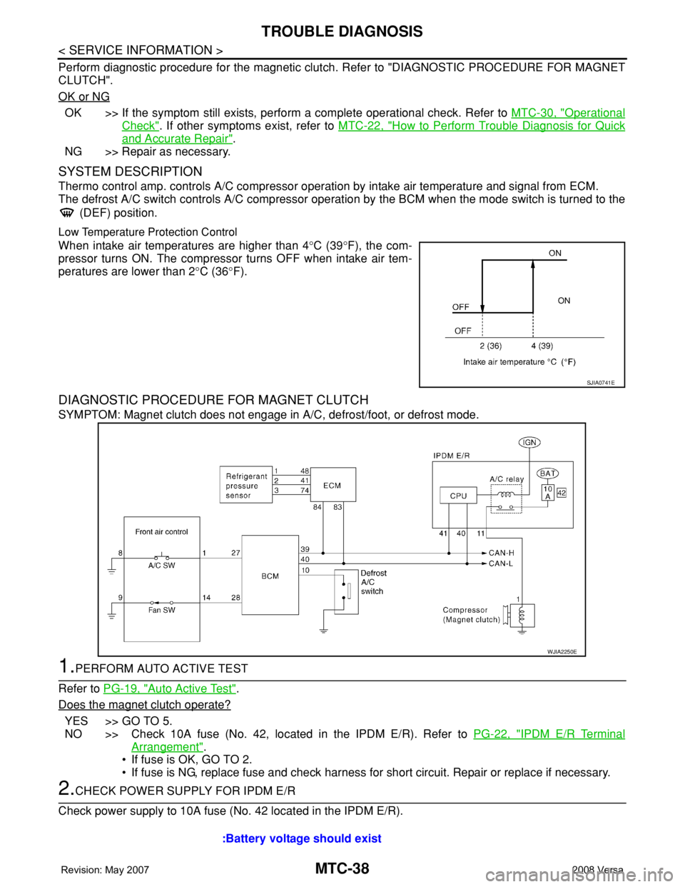
SYSTEM DESCRIPTION
Thermo control amp. controls A/C compressor operation by intake air temperature and signal from ECM.
The defrost A/C switch controls A/C compressor operation by the BCM when the mode switch is turned to the
(DEF) position.
Low Temperature Protection Control
When intake air temperatures are higher than 4°C (39°F), the com-
pressor turns ON. The compressor turns OFF when intake air tem-
peratures are lower than 2°C (36°F).
DIAGNOSTIC PROCEDURE FOR MAGNET CLUTCH
SYMPTOM: Magnet clutch does not engage in A/C, defrost/foot, or defrost mode.
1.PERFORM AUTO ACTIVE TEST
Refer to PG-19, "
Auto Active Test".
Does the magnet clutch operate?
YES >> GO TO 5.
NO >> Check 10A fuse (No. 42, located in the IPDM E/R). Refer to PG-22, "
IPDM E/R Terminal
Arrangement".
• If fuse is OK, GO TO 2.
• If fuse is NG, replace fuse and check harness for short circuit. Repair or replace if necessary.
2.CHECK POWER SUPPLY FOR IPDM E/R
Check power supply to 10A fuse (No. 42 located in the IPDM E/R).
SJIA0741E
WJIA2250E
:Battery voltage should exist
Page 2381 of 2771

TROUBLE DIAGNOSIS
MTC-43
< SERVICE INFORMATION >
C
D
E
F
G
H
I
K
L
MA
B
MTC
N
O
P
OK or NG
OK >> • GO TO 18 (with CVT).
• GO TO 19 (without CVT).
NG >> GO TO 21.
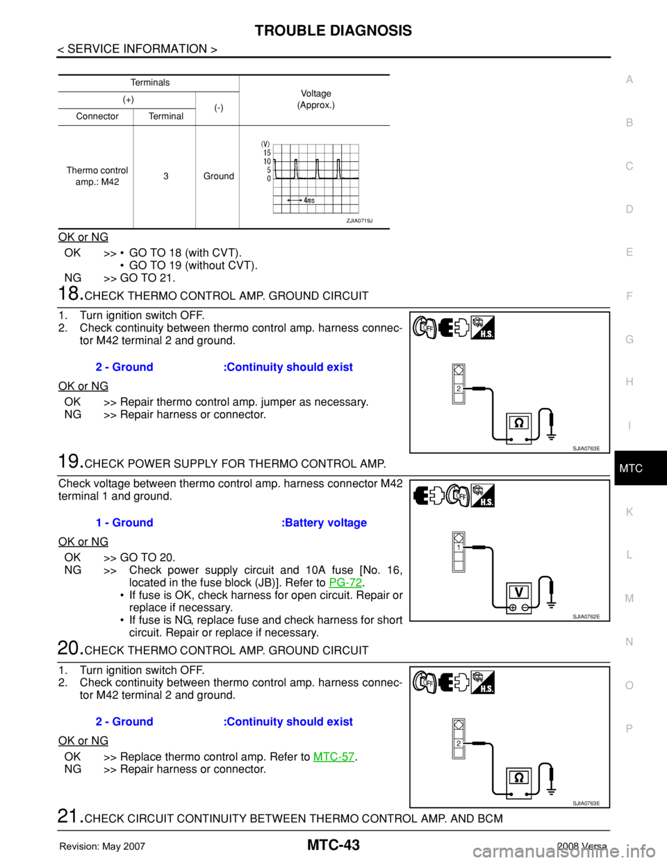
18.CHECK THERMO CONTROL AMP. GROUND CIRCUIT
1. Turn ignition switch OFF.
2. Check continuity between thermo control amp. harness connec-
tor M42 terminal 2 and ground.
OK or NG
OK >> Repair thermo control amp. jumper as necessary.
NG >> Repair harness or connector.
19.CHECK POWER SUPPLY FOR THERMO CONTROL AMP.
Check voltage between thermo control amp. harness connector M42
terminal 1 and ground.
OK or NG
OK >> GO TO 20.
NG >> Check power supply circuit and 10A fuse [No. 16,
located in the fuse block (JB)]. Refer to PG-72
.
• If fuse is OK, check harness for open circuit. Repair or
replace if necessary.
• If fuse is NG, replace fuse and check harness for short
circuit. Repair or replace if necessary.
20.CHECK THERMO CONTROL AMP. GROUND CIRCUIT
1. Turn ignition switch OFF.
2. Check continuity between thermo control amp. harness connec-
tor M42 terminal 2 and ground.
OK or NG
OK >> Replace thermo control amp. Refer to MTC-57.
NG >> Repair harness or connector.
21.CHECK CIRCUIT CONTINUITY BETWEEN THERMO CONTROL AMP. AND BCM
Te r m i n a l s
Vol tag e
(Approx.) (+)
(-)
Connector Terminal
Thermo control
amp.: M423Ground
ZJIA0719J
2 - Ground :Continuity should exist
SJIA0763E
1 - Ground :Battery voltage
SJIA0762E
2 - Ground :Continuity should exist
SJIA0763E
Page 2434 of 2771

PG-1
ELECTRICAL
C
D
E
F
G
H
I
J
L
M
SECTION PG
A
B
PG
N
O
P
CONTENTS
POWER SUPPLY, GROUND & CIRCUIT ELEMENTS
SERVICE INFORMATION ............................2
PRECAUTIONS ...................................................2
Precaution for Supplemental Restraint System
(SRS) "AIR BAG" and "SEAT BELT PRE-TEN-
SIONER" ...................................................................
2
POWER SUPPLY ROUTING CIRCUIT ...............3
Schematic .................................................................3
Wiring Diagram - POWER - ......................................5
Fuse ........................................................................15
Fusible Link .............................................................15
Circuit Breaker (Built Into BCM) ..............................15
Circuit Breaker ........................................................15
IPDM E/R (INTELLIGENT POWER DISTRI-
BUTION MODULE ENGINE ROOM) .................
16
System Description .................................................16
CAN Communication System Description ...............17
Function of Detecting Ignition Relay Malfunction ....17
CONSULT-III Function (IPDM E/R) .........................17
Auto Active Test ......................................................19
IPDM E/R Terminal Arrangement ...........................22
Terminal and Reference Value for IPDM E/R .........23
IPDM E/R Power/Ground Circuit Inspection ...........25
Inspection with CONSULT-III (Self-Diagnosis) .......26
Removal and Installation of IPDM E/R ....................26
GROUND CIRCUIT ...........................................28
Ground Distribution ..................................................28
HARNESS .........................................................37
Harness Layout .......................................................37
Wiring Diagram Codes (Cell Codes) .......................58
ELECTRICAL UNITS LOCATION ....................61
Electrical Units Location ..........................................61
HARNESS CONNECTOR .................................65
Description ...............................................................65
ELECTRICAL UNITS ........................................68
Terminal Arrangement .............................................68
STANDARDIZED RELAY .................................69
Description ...............................................................69
SUPER MULTIPLE JUNCTION (SMJ) .............71
Terminal Arrangement .............................................71
FUSE BLOCK-JUNCTION BOX (J/B) ..............72
Terminal Arrangement .............................................72
FUSE AND FUSIBLE LINK BOX ......................73
Terminal Arrangement .............................................73
Page 2448 of 2771

POWER SUPPLY ROUTING CIRCUIT
PG-15
< SERVICE INFORMATION >
C
D
E
F
G
H
I
J
L
MA
B
PG
N
O
P
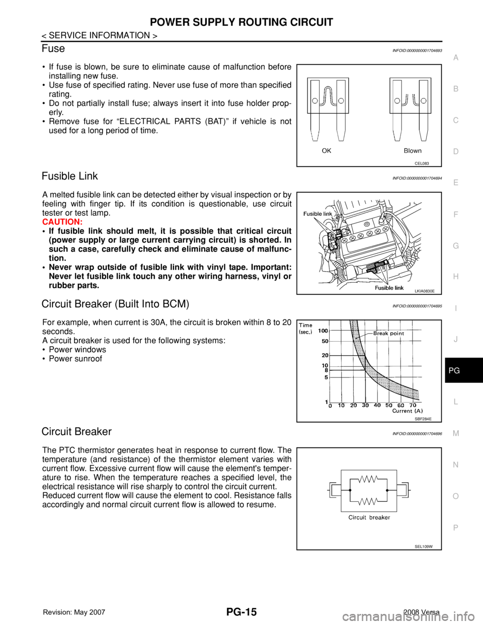
FuseINFOID:0000000001704693
• If fuse is blown, be sure to eliminate cause of malfunction before
installing new fuse.
• Use fuse of specified rating. Never use fuse of more than specified
rating.
• Do not partially install fuse; always insert it into fuse holder prop-
erly.
• Remove fuse for “ELECTRICAL PARTS (BAT)” if vehicle is not
used for a long period of time.
Fusible LinkINFOID:0000000001704694
A melted fusible link can be detected either by visual inspection or by
feeling with finger tip. If its condition is questionable, use circuit
tester or test lamp.
CAUTION:
• If fusible link should melt, it is possible that critical circuit
(power supply or large current carrying circuit) is shorted. In
such a case, carefully check and eliminate cause of malfunc-
tion.
• Never wrap outside of fusible link with vinyl tape. Important:
Never let fusible link touch any other wiring harness, vinyl or
rubber parts.
Circuit Breaker (Built Into BCM)INFOID:0000000001704695
For example, when current is 30A, the circuit is broken within 8 to 20
seconds.
A circuit breaker is used for the following systems:
• Power windows
• Power sunroof
Circuit BreakerINFOID:0000000001704696
The PTC thermistor generates heat in response to current flow. The
temperature (and resistance) of the thermistor element varies with
current flow. Excessive current flow will cause the element's temper-
ature to rise. When the temperature reaches a specified level, the
electrical resistance will rise sharply to control the circuit current.
Reduced current flow will cause the element to cool. Resistance falls
accordingly and normal circuit current flow is allowed to resume.
CEL083
LKIA0830E
SBF284E
SEL109W
Page 2449 of 2771

PG-16
< SERVICE INFORMATION >
IPDM E/R (INTELLIGENT POWER DISTRIBUTION MODULE ENGINE ROOM)
IPDM E/R (INTELLIGENT POWER DISTRIBUTION MODULE ENGINE
ROOM)
System DescriptionINFOID:0000000001704697
• IPDM E/R (Intelligent Power Distribution Module Engine Room) integrates the relay box and fuse block
which were originally placed in engine compartment. It controls integrated relays via IPDM E/R control cir-
cuits.
• IPDM E/R-integrated control circuits perform ON-OFF operation of relays, CAN communication control, oil
pressure switch signal reception, etc.
• It controls operation of each electrical component via ECM, BCM and CAN communication lines.
CAUTION:
None of the IPDM E/R integrated relays can be removed.
SYSTEMS CONTROLLED BY IPDM E/R
1. Lamp control
Using CAN communication lines, it receives signals from the BCM and controls the following lamps:
• Headlamps (High, Low)
• Parking lamps
• Tail and license plate lamps
• Front fog lamps
2. Wiper control
Using CAN communication lines, it receives signals from the BCM and controls the front wipers.
3. Rear window defogger relay control
Using CAN communication lines, it receives signals from the BCM and controls the rear window defogger
relay.
4. A/C compressor control
Using CAN communication lines, it receives signals from the ECM and controls the A/C compressor
(magnet clutch).
5. Starter control
Using CAN communication lines, it receives signals from the BCM and controls the starter relay.
6. Cooling fan control
Using CAN communication lines, it receives signals from the ECM and controls the cooling fan relays.
7. Horn control
Using CAN communication lines, it receives signals from the BCM and controls the horn relay.
8. Daytime light system control (Canada only)
Using CAN communication lines, it receives signals from the BCM and controls the daytime light relay.
CAN COMMUNICATION LINE CONTROL
With CAN communication, by connecting each control unit using two communication lines (CAN L-line, CAN
H-line), it is possible to transmit a maximum amount of information with minimum wiring. Each control unit can
transmit and receive data, and reads necessary information only.
1. Fail-safe control
• When CAN communication with other control units is impossible, IPDM E/R performs fail-safe control.
After CAN communication returns to normal operation, it also returns to normal control.
• Operation of control parts by IPDM E/R during fail-safe mode is as follows:
Controlled system Fail-safe mode
Headlamp• With the ignition switch ON, headlamp low relay is ON, headlamp high relays are OFF, and
daytime light system (Canada only) is OFF.
• With the ignition switch OFF, the headlamp relays are OFF.
Tail, license plate and parking lamps • With the ignition switch ON, the tail lamp relay is ON.
• With the ignition switch OFF, the tail lamp relay is OFF.
Cooling fan• With the ignition switch ON, cooling fan relay-1, relay-2, and relay-3 are ON.
• With the ignition switch OFF, all cooling fan relays are OFF.
Front wiperUntil the ignition switch is turned off, the front wiper relays remain in the same status they
were in just before fail−safe control was initiated.
Page 2456 of 2771

IPDM E/R (INTELLIGENT POWER DISTRIBUTION MODULE ENGINE ROOM)
PG-23
< SERVICE INFORMATION >
C
D
E
F
G
H
I
J
L
MA
B
PG
N
O
P
Terminal and Reference Value for IPDM E/RINFOID:0000000001704703
Te r m i n a lWire
colorSignal nameSignal
input/
outputMeasuring condition
Reference value
(Approx.) Ignition
switchOperation or condition
1 R Battery power supply Input OFF — Battery voltage
2 G Battery power supply Input OFF — Battery voltage
3YECM Relay Output—Ignition switch ON or START Battery voltage
Ignition switch OFF or ACC 0V
4GECM relay Output—Ignition switch ON or START Battery voltage
Ignition switch OFF or ACC 0V
6RDaytime light relay
controlInput ON Daytime light system active. Less than battery voltage
Daytime light system inactive. Battery voltage
7 G ECM relay control Input —Ignition switch ON or START 0V
Ignition switch OFF or ACC Battery voltage
8GThrottle control motor
relayOutput —Ignition switch ON or START Battery voltage
Ignition switch OFF or ACC 0V
11 W A/C compressor OutputON or
STARTA/C switch ON or defrost A/C
switchBattery voltage
A/C switch OFF or defrost A/C
switch0V
12 OIgnition switch sup-
plied powerInput —OFF or ACC 0V
ON or START Battery voltage
14LG
(M/T)
R
(A/T
or
CVT)Fuse 49 Output —Ignition switch ON or START Battery voltage
Ignition switch OFF or ACC 0V
15 V Fuse 50 Output —Ignition switch ON or START Battery voltage
Ignition switch OFF or ACC 0V
16 BR Fuse 51 Output —Ignition switch ON or START Battery voltage
Ignition switch OFF or ACC 0V
17 Y Battery power supply Output — — Battery voltage
19 R Starter motor Output START — Battery voltage
20L
(with
A/C)
LG
(with-
out A/
C)Cooling fan relay-1 Output —Conditions correct for cooling
fan low operation.Battery voltage
Conditions not correct for
cooling fan low operation.0V
22 G Battery power supply Input — — Battery voltage
23 L Cooling fan relay-2 Input —Conditions correct for cooling
fan high operationBattery voltage
Conditions not correct for
cooling fan high operation0V