2008 NISSAN TIIDA PN switch
[x] Cancel search: PN switchPage 2752 of 2771
FRONT WIPER AND WASHER SYSTEM
WW-19
< SERVICE INFORMATION >
C
D
E
F
G
H
I
J
L
MA
B
WW
N
O
P
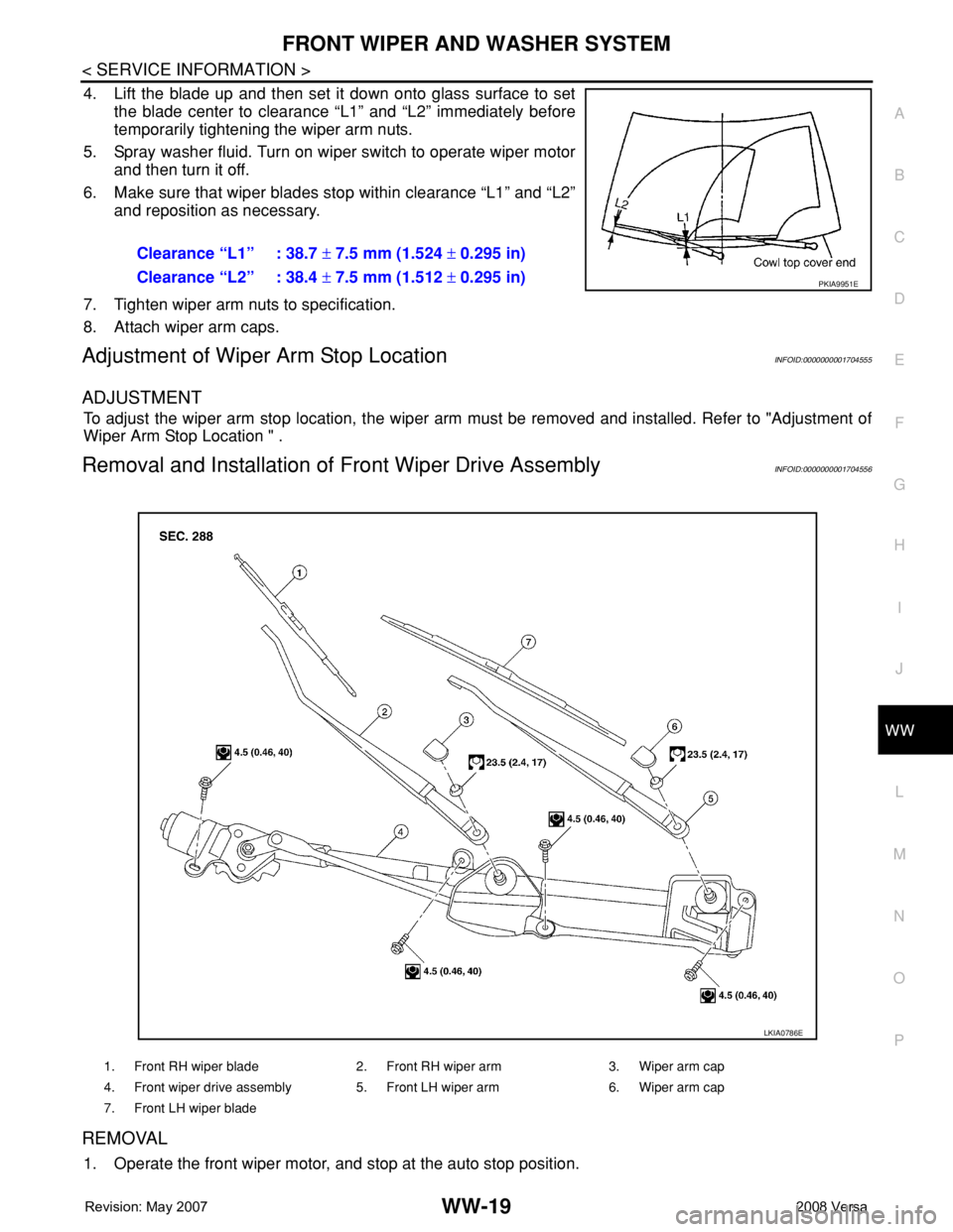
4. Lift the blade up and then set it down onto glass surface to set
the blade center to clearance “L1” and “L2” immediately before
temporarily tightening the wiper arm nuts.
5. Spray washer fluid. Turn on wiper switch to operate wiper motor
and then turn it off.
6. Make sure that wiper blades stop within clearance “L1” and “L2”
and reposition as necessary.
7. Tighten wiper arm nuts to specification.
8. Attach wiper arm caps.
Adjustment of Wiper Arm Stop LocationINFOID:0000000001704555
ADJUSTMENT
To adjust the wiper arm stop location, the wiper arm must be removed and installed. Refer to "Adjustment of
Wiper Arm Stop Location " .
Removal and Installation of Front Wiper Drive AssemblyINFOID:0000000001704556
REMOVAL
1. Operate the front wiper motor, and stop at the auto stop position.Clearance “L1” : 38.7 ± 7.5 mm (1.524 ± 0.295 in)
Clearance “L2” : 38.4 ± 7.5 mm (1.512 ± 0.295 in)
PKIA9951E
1. Front RH wiper blade 2. Front RH wiper arm 3. Wiper arm cap
4. Front wiper drive assembly 5. Front LH wiper arm 6. Wiper arm cap
7. Front LH wiper blade
LKIA0786E
Page 2753 of 2771
WW-20
< SERVICE INFORMATION >
FRONT WIPER AND WASHER SYSTEM
2. Remove wiper arms. Refer to WW-18, "Removal and Installation of Front Wiper Arms" .
3. Remove cowl top cover. Refer to EI-21
.
4. Disconnect wiper motor connector.
5. Remove front wiper drive assembly bolts, and remove front wiper drive assembly.
INSTALLATION
1. Install front wiper drive assembly.
2. Connect wiper motor connector. Turn wiper switch on to operate wiper motor, then turn wiper switch off
(auto stop).
3. Install cowl top cover. Refer to EI-21
.
4. Install the wiper arms. Refer to WW-18, "
Removal and Installation of Front Wiper Arms" .
Removal and Installation of Front Washer NozzleINFOID:0000000001704557
REMOVAL
1. Remove cowl top cover. Refer to EI-21, "Removal and Installation" .
2. Remove washer tube.
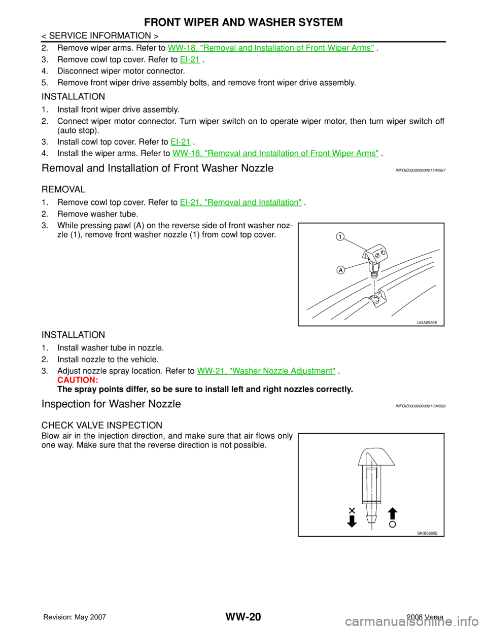
3. While pressing pawl (A) on the reverse side of front washer noz-
zle (1), remove front washer nozzle (1) from cowl top cover.
INSTALLATION
1. Install washer tube in nozzle.
2. Install nozzle to the vehicle.
3. Adjust nozzle spray location. Refer to WW-21, "
Washer Nozzle Adjustment" .
CAUTION:
The spray points differ, so be sure to install left and right nozzles correctly.
Inspection for Washer NozzleINFOID:0000000001704558
CHECK VALVE INSPECTION
Blow air in the injection direction, and make sure that air flows only
one way. Make sure that the reverse direction is not possible.
LKIA0939E
SKIB5665E
Page 2755 of 2771
WW-22
< SERVICE INFORMATION >
FRONT WIPER AND WASHER SYSTEM
Removal and Installation of Front Wiper and Washer Switch
INFOID:0000000001704561
REMOVAL
1. Remove the steering column cover. Refer to IP-10 .
2. Disconnect the wiper and washer switch connector.
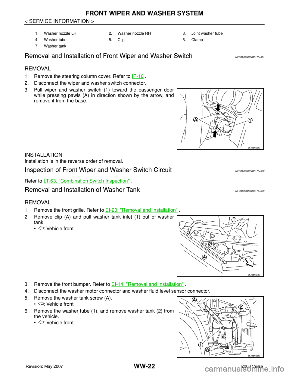
3. Pull wiper and washer switch (1) toward the passenger door
while pressing pawls (A) in direction shown by the arrow, and
remove it from the base.
INSTALLATION
Installation is in the reverse order of removal.
Inspection of Front Wiper and Washer Switch CircuitINFOID:0000000001704562
Refer to LT-63, "Combination Switch Inspection" .
Removal and Installation of Washer TankINFOID:0000000001704563
REMOVAL
1. Remove the front grille. Refer to EI-20, "Removal and Installation" .
2. Remove clip (A) and pull washer tank inlet (1) out of washer
tank.
• : Vehicle front
3. Remove the front bumper. Refer to EI-14, "
Removal and Installation" .
4. Disconnect the washer motor connector and washer fluid level sensor connector.
5. Remove the washer tank screw (A).
• : Vehicle front
6. Remove the washer tube (1), and remove washer tank (2) from
the vehicle.
• : Vehicle front
1. Washer nozzle LH 2. Washer nozzle RH 3. Joint washer tube
4. Washer tube 5. Clip 6. Clamp
7. Washer tank
SKIB5666E
SKIB5667E
SKIB5668E
Page 2757 of 2771
WW-24
< SERVICE INFORMATION >
REAR WIPER AND WASHER SYSTEM
REAR WIPER AND WASHER SYSTEM
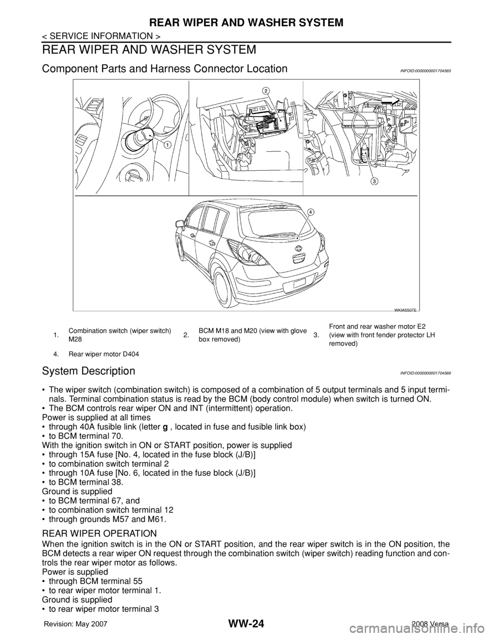
Component Parts and Harness Connector LocationINFOID:0000000001704565
System DescriptionINFOID:0000000001704566
• The wiper switch (combination switch) is composed of a combination of 5 output terminals and 5 input termi-
nals. Terminal combination status is read by the BCM (body control module) when switch is turned ON.
• The BCM controls rear wiper ON and INT (intermittent) operation.
Power is supplied at all times
• through 40A fusible link (letter g , located in fuse and fusible link box)
• to BCM terminal 70.
With the ignition switch in ON or START position, power is supplied
• through 15A fuse [No. 4, located in the fuse block (J/B)]
• to combination switch terminal 2
• through 10A fuse [No. 6, located in the fuse block (J/B)]
• to BCM terminal 38.
Ground is supplied
• to BCM terminal 67, and
• to combination switch terminal 12
• through grounds M57 and M61.
REAR WIPER OPERATION
When the ignition switch is in the ON or START position, and the rear wiper switch is in the ON position, the
BCM detects a rear wiper ON request through the combination switch (wiper switch) reading function and con-
trols the rear wiper motor as follows.
Power is supplied
• through BCM terminal 55
• to rear wiper motor terminal 1.
Ground is supplied
• to rear wiper motor terminal 3
WKIA5507E
1.Combination switch (wiper switch)
M282.BCM M18 and M20 (view with glove
box removed)3.Front and rear washer motor E2
(view with front fender protector LH
removed)
4. Rear wiper motor D404
Page 2758 of 2771
REAR WIPER AND WASHER SYSTEM
WW-25
< SERVICE INFORMATION >
C
D
E
F
G
H
I
J
L
MA
B
WW
N
O
P
• through grounds B117, B132 and D402.
With power and ground supplied, the rear wiper motor operates.
INTERMITTENT OPERATION
The rear wiper motor operates the wiper arm at low speed approximately every 7 seconds.
When the wiper switch is in the rear wiper INT position, the BCM detects a rear wiper INT request through the
combination switch (wiper switch) reading function.
When BCM operates rear wiper motor, power is supplied
• through BCM terminal 55
• to rear wiper motor terminal 1.
Ground is supplied
• to rear wiper motor terminal 3
• through grounds B117, B132 and D402.
With power and ground supplied, the rear wiper operates in intermittent mode.
AUTO STOP OPERATION
When the rear wiper arm is not located at the base of the rear window, and the rear wiper switch is turned
OFF, the rear wiper motor will continue to operate until the rear wiper arm is at the base of the rear window.
When the rear wiper arm reaches the base, rear wiper motor terminals 2 and 1 are connected.
Ground is supplied
• to BCM terminal 44
• through rear wiper motor terminal 2, and
• through rear wiper motor terminal 3, and
• through grounds B117, B132 and D402.
REAR WASHER OPERATION
When the ignition switch is in the ON or START position, and the front and rear washer switches are OFF, the
front and rear washer motor is supplied power
• through 15A fuse [No. 4, located in the fuse block (J/B)]
• to combination switch (wiper switch) terminal 14
• through combination switch (wiper switch) terminal 11
• to front and rear washer motor terminal 2.
When the rear wiper switch is in rear washer position, the BCM detects a rear washer signal by BCM wiper
switch reading function. Combination switch ground is supplied
• to front and rear washer motor terminal 1
• through combination switch (wiper switch) terminal 13, and
• through combination switch (wiper switch) terminal 12
• through grounds M57 and M61.
With ground supplied, the front and rear washer motor is operated in the rear direction.
When the BCM detects that the rear washer motor has operated for 0.4 seconds or longer, BCM operates the
rear wiper motor.
When the BCM detects that the rear washer switch is in OFF, the rear wiper motor cycles approximately 3
times and then stops.
If the rear washer is operated with the rear wiper switch in the INT position, normal rear wiper operation will
take over. Once the rear washer switch is released the rear wiper will return to INT operation.
BCM Combination Switch Reading Function
Refer to BCS-3, "System Description" .
Page 2761 of 2771
WW-28
< SERVICE INFORMATION >
REAR WIPER AND WASHER SYSTEM
3. Perform the Preliminary Check. Refer to WW-28, "Preliminary Check" .
4. Check symptom and repair or replace the cause of malfunction.
5. Does the rear wiper operate normally? If YES: GO TO 6. If NO: GO TO 4.
6. Inspection End.
Preliminary CheckINFOID:0000000001704570
CHECK POWER SUPPLY AND GROUND CIRCUIT FOR BCM
Refer to BCS-15, "BCM Power Supply and Ground Circuit Inspection" .
CONSULT-III Function (BCM)INFOID:0000000001704571
Refer to WW-10, "CONSULT-III Function (BCM)" .
Rear Wiper Does Not OperateINFOID:0000000001704572
1.REAR WIPER ACTIVE TEST
1. Select "BCM" on CONSULT-III, and select "WIPER" on "SELECT TEST ITEM" screen.
2. Select "ACTIVE TEST" on "SELECT DIAG MODE" screen.
3. Select "RR WIPER" on "SELECT TEST ITEM" screen.
4. Make sure rear wiper operates.
OK or NG
OK >> GO TO 6.
NG >> GO TO 2.
2.CHECK REAR WIPER MOTOR CIRCUIT
1. Turn ignition switch OFF.
2. Disconnect BCM and rear wiper motor.
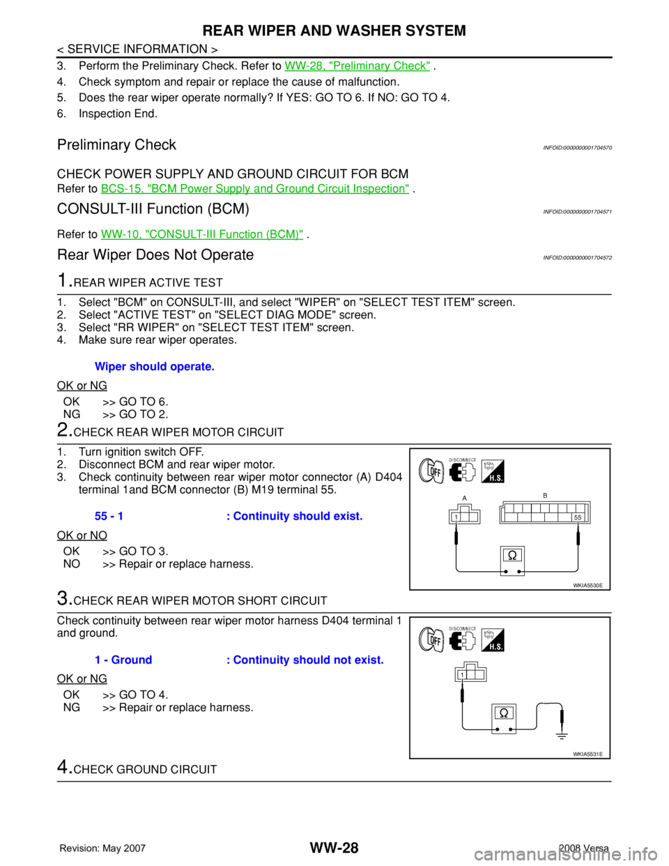
3. Check continuity between rear wiper motor connector (A) D404
terminal 1and BCM connector (B) M19 terminal 55.
OK or NO
OK >> GO TO 3.
NO >> Repair or replace harness.
3.CHECK REAR WIPER MOTOR SHORT CIRCUIT
Check continuity between rear wiper motor harness D404 terminal 1
and ground.
OK or NG
OK >> GO TO 4.
NG >> Repair or replace harness.
4.CHECK GROUND CIRCUIT Wiper should operate.
55 - 1 : Continuity should exist.
WKIA5530E
1 - Ground : Continuity should not exist.
WKIA5531E
Page 2762 of 2771
REAR WIPER AND WASHER SYSTEM
WW-29
< SERVICE INFORMATION >
C
D
E
F
G
H
I
J
L
MA
B
WW
N
O
P
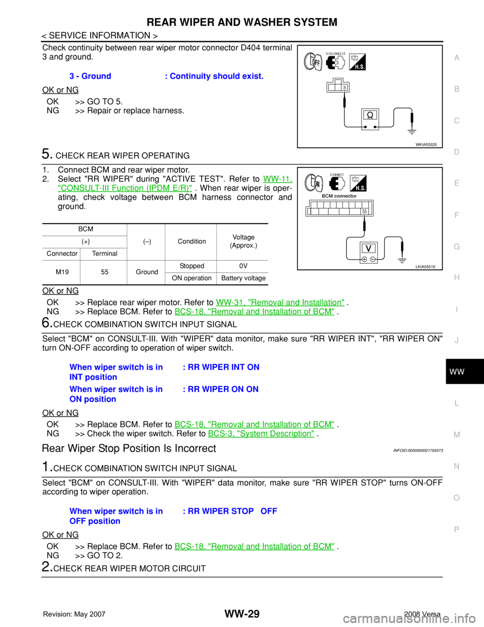
Check continuity between rear wiper motor connector D404 terminal
3 and ground.
OK or NG
OK >> GO TO 5.
NG >> Repair or replace harness.
5. CHECK REAR WIPER OPERATING
1. Connect BCM and rear wiper motor.
2. Select "RR WIPER" during "ACTIVE TEST". Refer to WW-11,
"CONSULT-III Function (IPDM E/R)" . When rear wiper is oper-
ating, check voltage between BCM harness connector and
ground.
OK or NG
OK >> Replace rear wiper motor. Refer to WW-31, "Removal and Installation" .
NG >> Replace BCM. Refer to BCS-18, "
Removal and Installation of BCM" .
6.CHECK COMBINATION SWITCH INPUT SIGNAL
Select "BCM" on CONSULT-III. With "WIPER" data monitor, make sure "RR WIPER INT", "RR WIPER ON"
turn ON-OFF according to operation of wiper switch.
OK or NG
OK >> Replace BCM. Refer to BCS-18, "Removal and Installation of BCM" .
NG >> Check the wiper switch. Refer to BCS-3, "
System Description" .
Rear Wiper Stop Position Is IncorrectINFOID:0000000001704573
1.CHECK COMBINATION SWITCH INPUT SIGNAL
Select "BCM" on CONSULT-III. With "WIPER" data monitor, make sure "RR WIPER STOP" turns ON-OFF
according to wiper operation.
OK or NG
OK >> Replace BCM. Refer to BCS-18, "Removal and Installation of BCM" .
NG >> GO TO 2.
2.CHECK REAR WIPER MOTOR CIRCUIT3 - Ground : Continuity should exist.
WKIA5532E
BCM
(–) ConditionVo l ta g e
(Approx.) (+)
Connector Terminal
M19 55 GroundStopped 0V
ON operation Battery voltage
LKIA0551E
When wiper switch is in
INT position: RR WIPER INT ON
When wiper switch is in
ON position: RR WIPER ON ON
When wiper switch is in
OFF position: RR WIPER STOP OFF
Page 2763 of 2771
WW-30
< SERVICE INFORMATION >
REAR WIPER AND WASHER SYSTEM
1. Turn ignition switch OFF.
2. Disconnect BCM and rear wiper motor.
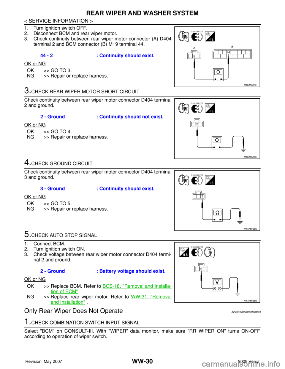
3. Check continuity between rear wiper motor connector (A) D404
terminal 2 and BCM connector (B) M19 terminal 44.
OK or NG
OK >> GO TO 3.
NG >> Repair or replace harness.
3.CHECK REAR WIPER MOTOR SHORT CIRCUIT
Check continuity between rear wiper motor connector D404 terminal
2 and ground.
OK or NG
OK >> GO TO 4.
NG >> Repair or replace harness.
4.CHECK GROUND CIRCUIT
Check continuity between rear wiper motor connector D404 terminal
3 and ground.
OK or NG
OK >> GO TO 5.
NG >> Repair or replace harness.
5.CHECK AUTO STOP SIGNAL
1. Connect BCM.
2. Turn ignition switch ON.
3. Check voltage between rear wiper motor connector D404 termi-
nal 2 and ground.
OK or NG
OK >> Replace BCM. Refer to BCS-18, "Removal and Installa-
tion of BCM" .
NG >> Replace rear wiper motor. Refer to WW-31, "
Removal
and Installation" .
Only Rear Wiper Does Not OperateINFOID:0000000001704574
1.CHECK COMBINATION SWITCH INPUT SIGNAL
Select "BCM" on CONSULT-III. With "WIPER" data monitor, make sure "RR WIPER ON" turns ON-OFF
according to operation of wiper switch.44 - 2 : Continuity should exist.
WKIA5533E
2 - Ground : Continuity should not exist.
WKIA5534E
3 - Ground : Continuity should exist.
WKIA5535E
2 - Ground : Battery voltage should exist.
WKIA5536E