Page 2397 of 2771

A/C UNIT ASSEMBLY
MTC-59
< SERVICE INFORMATION >
C
D
E
F
G
H
I
K
L
MA
B
MTC
N
O
P
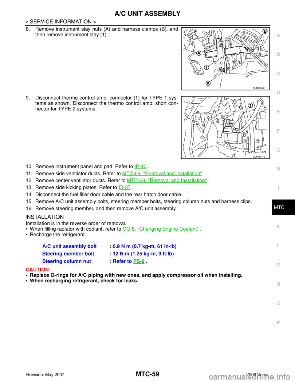
8. Remove instrument stay nuts (A) and harness clamps (B), and
then remove instrument stay (1).
9. Disconnect thermo control amp. connector (1) for TYPE 1 sys-
tems as shown. Disconnect the thermo control amp. short con-
nector for TYPE 2 systems.
10. Remove instrument panel and pad. Refer to IP-10
.
11. Remove side ventilator ducts. Refer to MTC-69, "
Removal and Installation" .
12. Remove center ventilator ducts. Refer to MTC-69, "
Removal and Installation" .
13. Remove side kicking plates. Refer to EI-37
.
14. Disconnect the fuel filler door cable and the rear hatch door cable.
15. Remove A/C unit assembly bolts, steering member bolts, steering column nuts and harness clips.
16. Remove steering member, and then remove A/C unit assembly.
INSTALLATION
Installation is in the reverse order of removal.
• When filling radiator with coolant, refer to CO-8, "
Changing Engine Coolant" .
• Recharge the refrigerant.
CAUTION:
• Replace O-rings for A/C piping with new ones, and apply compressor oil when installing.
• When recharging refrigerant, check for leaks.
SJIA0646E
SJIA0647E
A/C unit assembly bolt : 6.9 N·m (0.7 kg-m, 61 in-lb)
Steering member bolt : 12 N·m (1.25 kg-m, 9 ft-lb)
Steering column nut : Refer to PS-9
.
Page 2400 of 2771
MTC-62
< SERVICE INFORMATION >
BLOWER MOTOR
BLOWER MOTOR
Removal and InstallationINFOID:0000000001704314
REMOVAL
1. Remove instrument panel and pad. Refer to IP-10.
2. Remove side ventilator duct (right). Refer to MTC-69, "
Removal and Installation".
3. Disconnect blower motor connector (1).
4. Push the flange holding hook (A) toward the blower motor (2),
then rotate the blower motor (2) clockwise and remove it from
the A/C unit assembly.
CAUTION:
When blower fan and blower motor are assembled, the bal-
ance is adjusted, do not disassemble to replace the individ-
ual parts.
INSTALLATION
Installation is in the reverse order of removal.
CAUTION:
Rotate the blower motor until the blower motor flange holding hook locks securely in A/C unit assem-
bly.
LJIA0199E
Page 2404 of 2771
MTC-66
< SERVICE INFORMATION >
BLOWER FAN RESISTOR
BLOWER FAN RESISTOR
Removal and InstallationINFOID:0000000001704318
REMOVAL
1. Remove the instrument lower finisher. Refer to IP-10.
2. Remove the console side cover. Refer to IP-10
.
3. Remove the brake pedal assembly. Refer to BR-5
.
4. Disconnect the blower fan resistor connector.
5. Remove the blower fan resistor screws (A), then remove the
blower fan resistor (1).
INSTALLATION
Installation is in the reverse order of removal.
SJIA0656E
Page 2416 of 2771
MTC-78
< SERVICE INFORMATION >
REFRIGERANT LINES
Idler Pulley - Without A/C
Refer to MTC-4, "Precaution for Refrigerant Connection".
Removal and Installation of CompressorINFOID:0000000001704324
REMOVAL
1. Use the recovery/recycling equipment to evacuate the refrigerant.
2. Remove the two engine undercovers, using power tools.
3. Remove low-pressure flexible hose nut (A) and high-pressure
flexible hose bolt (B) from compressor.
CAUTION:
Cap or wrap the joint of the pipe with suitable material such
as vinyl tape to avoid the entry of air.
NOTE:
Type 1 shown, type 2 is similar.
4. Remove A/C compressor belt. Refer to EM-13
.
5. Disconnect compressor connector (C).
6. Remove bolts (A) from compressor (1), using power tools.
7. Remove compressor (1) downward from the engine compart-
ment.
WJIA2204E
1. Idler pulley 2. Bracket 3. Shaft
SJIA0671E
SJIA0672E
Page 2419 of 2771

REFRIGERANT LINES
MTC-81
< SERVICE INFORMATION >
C
D
E
F
G
H
I
K
L
MA
B
MTC
N
O
P
Installation is in the reverse order of removal.
CAUTION:
• Replace O-rings of high-pressure flexible hose with a new ones, and apply compressor oil when
installing.
• When recharging refrigerant, check for leaks.
Removal and Installation of High-pressure PipeINFOID:0000000001704327
REMOVAL
1. Remove low-pressure flexible hose. Refer to MTC-79, "Removal and Installation of Low-Pressure Flexible
Hose".
2. Remove high-pressure pipe from the clips.
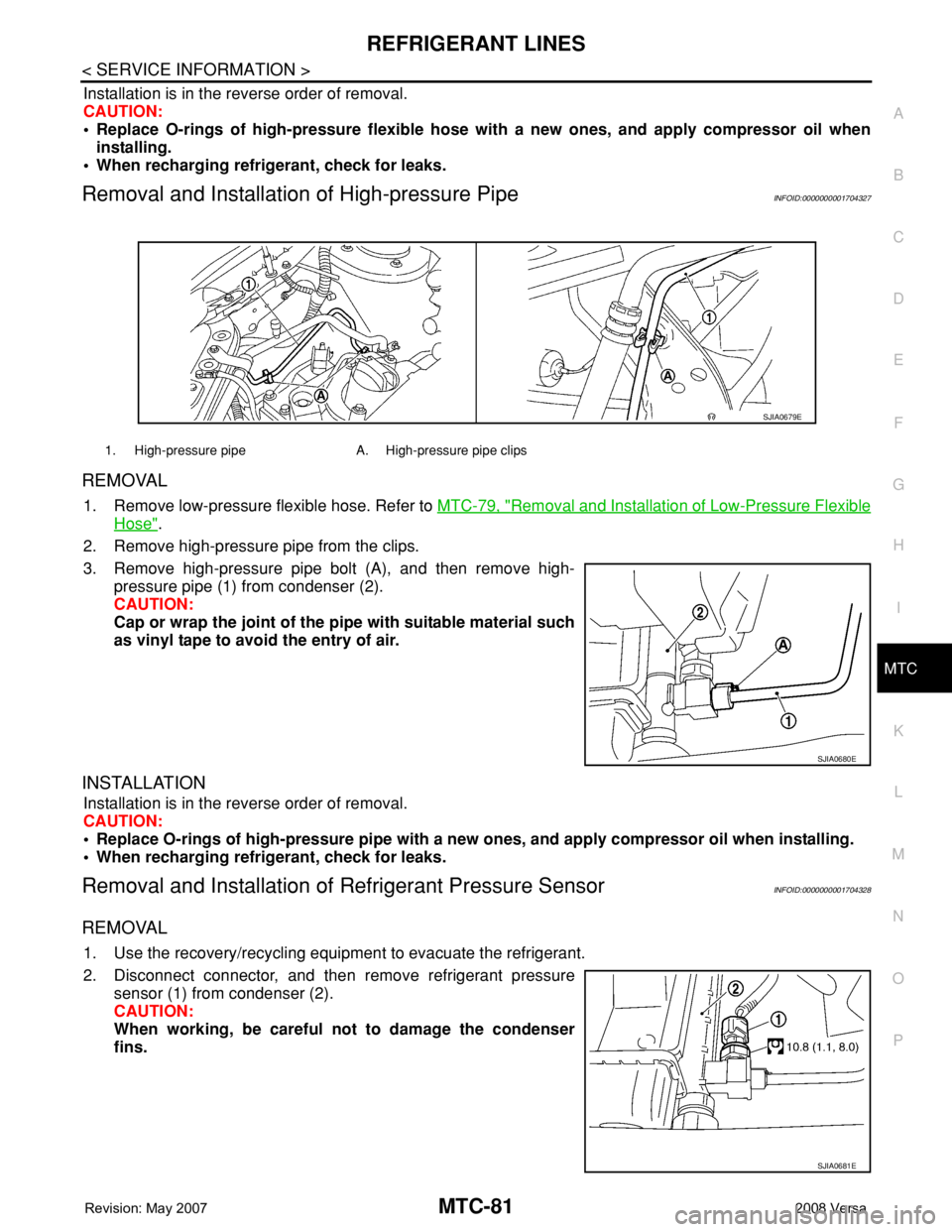
3. Remove high-pressure pipe bolt (A), and then remove high-
pressure pipe (1) from condenser (2).
CAUTION:
Cap or wrap the joint of the pipe with suitable material such
as vinyl tape to avoid the entry of air.
INSTALLATION
Installation is in the reverse order of removal.
CAUTION:
• Replace O-rings of high-pressure pipe with a new ones, and apply compressor oil when installing.
• When recharging refrigerant, check for leaks.
Removal and Installation of Refrigerant Pressure SensorINFOID:0000000001704328
REMOVAL
1. Use the recovery/recycling equipment to evacuate the refrigerant.
2. Disconnect connector, and then remove refrigerant pressure
sensor (1) from condenser (2).
CAUTION:
When working, be careful not to damage the condenser
fins.
1. High-pressure pipe A. High-pressure pipe clips
SJIA0679E
SJIA0680E
SJIA0681E
Page 2420 of 2771

MTC-82
< SERVICE INFORMATION >
REFRIGERANT LINES
INSTALLATION
Installation is in the reverse order of removal.
CAUTION:
• Replace O-rings of refrigerant pressure sensor with a new one, and apply compressor oil when
installing.
• When recharging refrigerant, check for leaks.
Removal and Installation of CondenserINFOID:0000000001704329
REMOVAL
1. Remove the three upper headlamp bolts to reposition the headlamps out of the way
2. Remove the radiator core support upper. Refer to BL-19
.
3. Remove high-pressure flexible hose and high-pressure pipe from condenser. Refer to MTC-80, "
Removal
and Installation of High-pressure Flexible Hose" and MTC-81, "Removal and Installation of High-pres-
sure Pipe" .
CAUTION:
Cap or wrap the joint of the pipe with suitable material such as vinyl tape to avoid the entry of air.
4. Disconnect refrigerant pressure sensor connector.
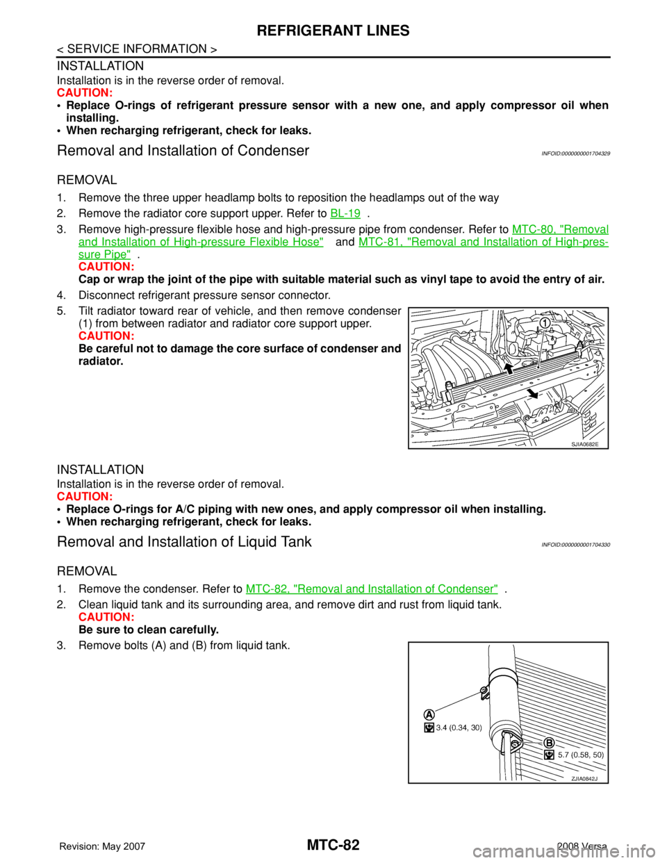
5. Tilt radiator toward rear of vehicle, and then remove condenser
(1) from between radiator and radiator core support upper.
CAUTION:
Be careful not to damage the core surface of condenser and
radiator.
INSTALLATION
Installation is in the reverse order of removal.
CAUTION:
• Replace O-rings for A/C piping with new ones, and apply compressor oil when installing.
• When recharging refrigerant, check for leaks.
Removal and Installation of Liquid TankINFOID:0000000001704330
REMOVAL
1. Remove the condenser. Refer to MTC-82, "Removal and Installation of Condenser" .
2. Clean liquid tank and its surrounding area, and remove dirt and rust from liquid tank.
CAUTION:
Be sure to clean carefully.
3. Remove bolts (A) and (B) from liquid tank.
SJIA0682E
ZJIA0842J
Page 2428 of 2771

PB-2
< SERVICE INFORMATION >
PRECAUTIONS
SERVICE INFORMATION
PRECAUTIONS
Precaution for Supplemental Restraint System (SRS) "AIR BAG" and "SEAT BELT
PRE-TENSIONER"
INFOID:0000000001703812
The Supplemental Restraint System such as “AIR BAG” and “SEAT BELT PRE-TENSIONER”, used along
with a front seat belt, helps to reduce the risk or severity of injury to the driver and front passenger for certain
types of collision. This system includes seat belt switch inputs and dual stage front air bag modules. The SRS
system uses the seat belt switches to determine the front air bag deployment, and may only deploy one front
air bag, depending on the severity of a collision and whether the front occupants are belted or unbelted.
Information necessary to service the system safely is included in the SRS and SB section of this Service Man-
ual.
WARNING:
• To avoid rendering the SRS inoperative, which could increase the risk of personal injury or death in
the event of a collision which would result in air bag inflation, all maintenance must be performed by
an authorized NISSAN/INFINITI dealer.
• Improper maintenance, including incorrect removal and installation of the SRS, can lead to personal
injury caused by unintentional activation of the system. For removal of Spiral Cable and Air Bag
Module, see the SRS section.
• Do not use electrical test equipment on any circuit related to the SRS unless instructed to in this
Service Manual. SRS wiring harnesses can be identified by yellow and/or orange harnesses or har-
ness connectors.
Page 2431 of 2771

PARKING BRAKE CONTROL
PB-5
< SERVICE INFORMATION >
C
D
E
G
H
I
J
K
L
MA
B
PB
N
O
P
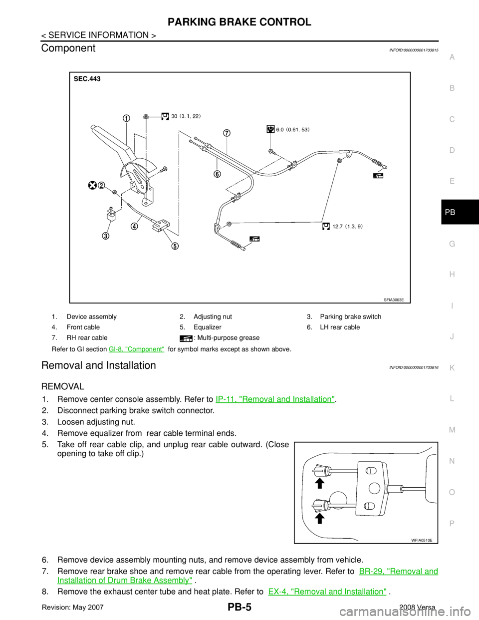
ComponentINFOID:0000000001703815
Removal and InstallationINFOID:0000000001703816
REMOVAL
1. Remove center console assembly. Refer to IP-11, "Removal and Installation".
2. Disconnect parking brake switch connector.
3. Loosen adjusting nut.
4. Remove equalizer from rear cable terminal ends.
5. Take off rear cable clip, and unplug rear cable outward. (Close
opening to take off clip.)
6. Remove device assembly mounting nuts, and remove device assembly from vehicle.
7. Remove rear brake shoe and remove rear cable from the operating lever. Refer to BR-29, "
Removal and
Installation of Drum Brake Assembly" .
8. Remove the exhaust center tube and heat plate. Refer to EX-4, "
Removal and Installation" .
1. Device assembly 2. Adjusting nut 3. Parking brake switch
4. Front cable 5. Equalizer 6. LH rear cable
7. RH rear cable : Multi-purpose grease
Refer to GI section GI-8, "
Component" for symbol marks except as shown above.
SFIA3063E
WFIA0510E