2008 NISSAN TIIDA connector d2
[x] Cancel search: connector d2Page 2556 of 2771
RF-26
< ON-VEHICLE REPAIR >
SUNROOF
CAUTION:
• Before installing the sunroof motor assembly, be sure the link assembly is in the symmetrical and
fully closed position.
• Align the link notch with the hole of the guide track (fully closed: RH and LH).
1. Place the sunroof motor assembly flat onto the sunroof unit assembly surface.
2. Laterally move the assembly little by little so that the gear is completely engaged into the wire and there is
no gap between the sunroof unit assembly and sunroof motor assembly.
3. Install the sunroof motor assembly screws, then connect the harness connector.
4. After installing, perform the initialization procedure. Refer to RF-10, "
System Description" .
LINK ASSEMBLY
Removal
1. Remove sunroof unit assembly. Refer to RF-21, "Removal and Installation".
2. Remove screws, then remove rear drain assembly.
3. Remove sunroof motor assembly. Refer to RF-21, "
Removal and Installation".
4. Remove link assembly from the rear end of the sunroof frame.
Installation
Installation is in the reverse order of removal.
Fitting AdjustmentINFOID:0000000001704208
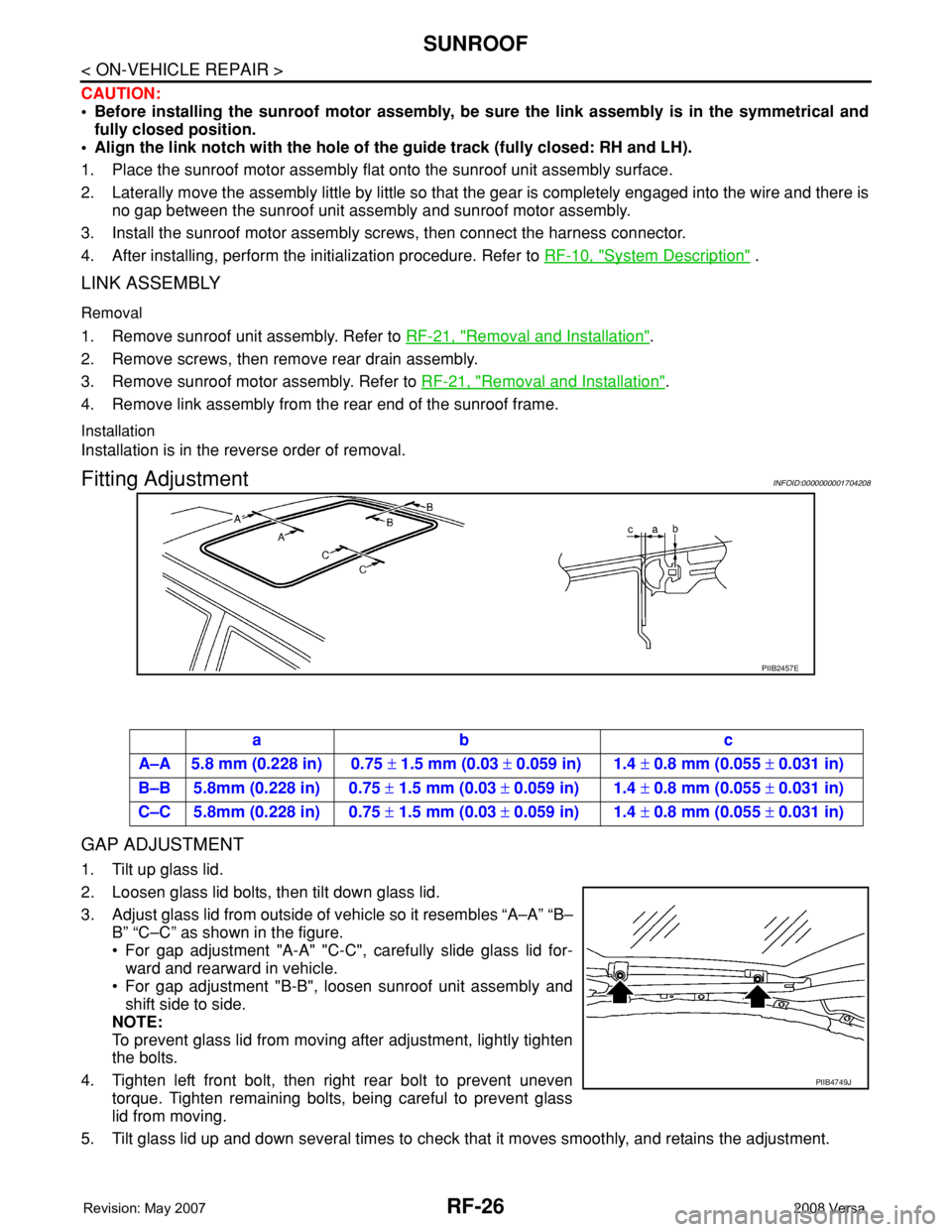
GAP ADJUSTMENT
1. Tilt up glass lid.
2. Loosen glass lid bolts, then tilt down glass lid.
3. Adjust glass lid from outside of vehicle so it resembles “A–A” “B–
B” “C–C” as shown in the figure.
• For gap adjustment "A-A" "C-C", carefully slide glass lid for-
ward and rearward in vehicle.
• For gap adjustment "B-B", loosen sunroof unit assembly and
shift side to side.
NOTE:
To prevent glass lid from moving after adjustment, lightly tighten
the bolts.
4. Tighten left front bolt, then right rear bolt to prevent uneven
torque. Tighten remaining bolts, being careful to prevent glass
lid from moving.
5. Tilt glass lid up and down several times to check that it moves smoothly, and retains the adjustment.
PIIB2457E
ab c
A–A 5.8 mm (0.228 in) 0.75 ± 1.5 mm (0.03 ± 0.059 in) 1.4 ± 0.8 mm (0.055 ± 0.031 in)
B–B 5.8mm (0.228 in) 0.75 ± 1.5 mm (0.03 ± 0.059 in) 1.4 ± 0.8 mm (0.055 ± 0.031 in)
C–C 5.8mm (0.228 in) 0.75 ± 1.5 mm (0.03 ± 0.059 in) 1.4 ± 0.8 mm (0.055 ± 0.031 in)
PIIB4749J
Page 2561 of 2771

RSU-2
< SERVICE INFORMATION >
PRECAUTIONS
SERVICE INFORMATION
PRECAUTIONS
Precaution for Supplemental Restraint System (SRS) "AIR BAG" and "SEAT BELT
PRE-TENSIONER"
INFOID:0000000001703732
The Supplemental Restraint System such as “AIR BAG” and “SEAT BELT PRE-TENSIONER”, used along
with a front seat belt, helps to reduce the risk or severity of injury to the driver and front passenger for certain
types of collision. This system includes seat belt switch inputs and dual stage front air bag modules. The SRS
system uses the seat belt switches to determine the front air bag deployment, and may only deploy one front
air bag, depending on the severity of a collision and whether the front occupants are belted or unbelted.
Information necessary to service the system safely is included in the SRS and SB section of this Service Man-
ual.
WARNING:
• To avoid rendering the SRS inoperative, which could increase the risk of personal injury or death in
the event of a collision which would result in air bag inflation, all maintenance must be performed by
an authorized NISSAN/INFINITI dealer.
• Improper maintenance, including incorrect removal and installation of the SRS, can lead to personal
injury caused by unintentional activation of the system. For removal of Spiral Cable and Air Bag
Module, see the SRS section.
• Do not use electrical test equipment on any circuit related to the SRS unless instructed to in this
Service Manual. SRS wiring harnesses can be identified by yellow and/or orange harnesses or har-
ness connectors.
Precaution for Rear SuspensionINFOID:0000000001703733
• When installing the rubber bushings, the final tightening must be done under unladen condition and with the
tires on level ground. Oil will shorten the life of the rubber bushings, so wipe off any spilled oil immediately.
• Unladen condition means the fuel tank, engine coolant and lubricants are at the full specification. The spare
tire, jack, hand tools, and mats are in their designated positions.
• After installing suspension components, check the wheel alignment.
• Caulking nuts are not reusable. Always use new caulking nuts for installation. New caulking nuts are pre-
oiled, do not apply any additional lubrication.
Page 2573 of 2771
SB-2
< PRECAUTION >
PRECAUTIONS
PRECAUTION
PRECAUTIONS
Precaution for Supplemental Restraint System (SRS) "AIR BAG" and "SEAT BELT
PRE-TENSIONER"
INFOID:0000000001703897
The Supplemental Restraint System such as “AIR BAG” and “SEAT BELT PRE-TENSIONER”, used along
with a front seat belt, helps to reduce the risk or severity of injury to the driver and front passenger for certain
types of collision. This system includes seat belt switch inputs and dual stage front air bag modules. The SRS
system uses the seat belt switches to determine the front air bag deployment, and may only deploy one front
air bag, depending on the severity of a collision and whether the front occupants are belted or unbelted.Infor-
mation necessary to service the system safely is included in the SR and SB section of this Service Manual.
WARNING:
• To avoid rendering the SRS inoperative, which could increase the risk of personal injury or death in
the event of a collision which would result in air bag inflation, all maintenance must be performed by
an authorized NISSAN/INFINITI dealer.
• Improper maintenance, including incorrect removal and installation of the SRS, can lead to personal
injury caused by unintentional activation of the system. For removal of Spiral Cable and Air Bag
Module, see the SRS section.
• Do not use electrical test equipment on any circuit related to the SRS unless instructed to in this
Service Manual. SRS wiring harnesses can be identified by yellow and/or orange harnesses or har-
ness connectors.
Precaution for Seat Belt ServiceINFOID:0000000001703898
CAUTION:
• Before removing the front seat belt pre-tensioner assembly, turn the ignition switch off, disconnect
the both battery cables and wait at least 3 minutes.
• After replacing or reinstalling front seat belt pre-tensioner assembly, or reconnecting front seat belt
pre-tensioner connector, check the system function. Refer to SRS-18, "
SRS Operation Check".
• Do not disassemble buckle or seat belt assembly.
• Do not reuse seat belt anchor bolts after removal. Replace with new ones.
• Replace anchor bolts if they are deformed or worn out.
• Never oil tongue and buckle.
• If any component of seat belt assembly is questionable, do not repair. Replace the whole seat belt
assembly.
• If webbing is cut, frayed, or damaged, replace seat belt assembly.
• When replacing seat belt assembly, use a genuine NISSAN seat belt assembly.
AFTER A COLLISION
WARNING:
• Inspect all seat belt assemblies including retractors and attaching hardware after any collision.
• NISSAN recommends that all seat belt assemblies in use during a collision be replaced unless the
collision was minor and the belts show no damage and continue to operate properly. Failure to do so
could result in serious personal injury in an accident. Seat belt assemblies not in use during a colli-
sion should also be replaced if either damage or improper operation is noted. Seat belt pre-tensioner
should be replaced even if the seat belts are not in use during a frontal collision in which the air bags
are deployed.
Replace any seat belt assembly (including anchor bolts) if:
• The seat belt was in use at the time of a collision (except for minor collisions and the belts, retractors and
buckles show no damage and continue to operate properly).
• The seat belt was damaged in an accident. (i.e. torn webbing, bent retractor or guide).
• The seat belt attaching point was damaged in an accident. Inspect the seat belt attaching area for damage
or distortion and repair as necessary before installing a new seat belt assembly.
• Anchor bolts are deformed or worn out.
• The seat belt pre-tensioner should be replaced even if the seat belts are not in use during the collision in
which the air bags are deployed.
Page 2574 of 2771
SEAT BELTS
SB-3
< ON-VEHICLE REPAIR >
C
D
E
F
G
I
J
K
L
MA
B
SB
N
O
P
ON-VEHICLE REPAIR
SEAT BELTS
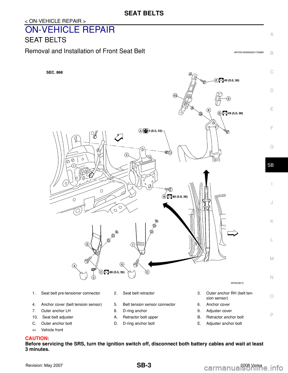
Removal and Installation of Front Seat BeltINFOID:0000000001703899
CAUTION:
Before servicing the SRS, turn the ignition switch off, disconnect both battery cables and wait at least
3 minutes.
1. Seat belt pre-tensioner connector 2. Seat belt retractor 3. Outer anchor RH (belt ten-
sion sensor)
4. Anchor cover (belt tension sensor) 5. Belt tension sensor connector 6. Anchor cover
7. Outer anchor LH 8. D-ring anchor 9. Adjuster cover
10. Seat belt adjuster A. Retractor bolt upper B. Retractor anchor bolt
C. Outer anchor bolt D. D-ring anchor bolt E. Adjuster anchor bolt
⇐Vehicle front
WHIA0361E
Page 2575 of 2771
SB-4
< ON-VEHICLE REPAIR >
SEAT BELTS
REMOVAL OF SEAT BELT RETRACTOR
1. Disconnect both the negative and positive battery cables, then wait at least 3 minutes.
2. Remove the adjuster cover and D-ring anchor bolt.
3. Remove both the center pillar upper and lower garnish. Refer to EI-37
.
WARNING:
Do not reuse center pillar upper garnish if removed.
4. Pull the floor trim away from center pillar.
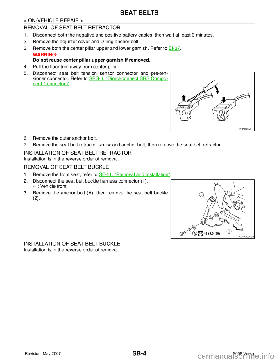
5. Disconnect seat belt tension sensor connector and pre-ten-
sioner connector. Refer to SRS-6, "
Direct-connect SRS Compo-
nent Connectors".
6. Remove the outer anchor bolt.
7. Remove the seat belt retractor screw and anchor bolt, then remove the seat belt retractor.
INSTALLATION OF SEAT BELT RETRACTOR
Installation is in the reverse order of removal.
REMOVAL OF SEAT BELT BUCKLE
1. Remove the front seat, refer to SE-11, "Removal and Installation".
2. Disconnect the seat belt buckle harness connector (1).
⇐: Vehicle front
3. Remove the anchor bolt (A), then remove the seat belt buckle
(2).
INSTALLATION OF SEAT BELT BUCKLE
Installation is in the reverse order of removal.
PHIA0953J
ALHIA0095GB
Page 2584 of 2771

SC-2
< SERVICE INFORMATION >
PRECAUTIONS
SERVICE INFORMATION
PRECAUTIONS
Precaution for Supplemental Restraint System (SRS) "AIR BAG" and "SEAT BELT
PRE-TENSIONER"
INFOID:0000000001704342
The Supplemental Restraint System such as “AIR BAG” and “SEAT BELT PRE-TENSIONER”, used along
with a front seat belt, helps to reduce the risk or severity of injury to the driver and front passenger for certain
types of collision. This system includes seat belt switch inputs and dual stage front air bag modules. The SRS
system uses the seat belt switches to determine the front air bag deployment, and may only deploy one front
air bag, depending on the severity of a collision and whether the front occupants are belted or unbelted.
Information necessary to service the system safely is included in the SRS and SB section of this Service Man-
ual.
WARNING:
• To avoid rendering the SRS inoperative, which could increase the risk of personal injury or death in
the event of a collision which would result in air bag inflation, all maintenance must be performed by
an authorized NISSAN/INFINITI dealer.
• Improper maintenance, including incorrect removal and installation of the SRS, can lead to personal
injury caused by unintentional activation of the system. For removal of Spiral Cable and Air Bag
Module, see the SRS section.
• Do not use electrical test equipment on any circuit related to the SRS unless instructed to in this
Service Manual. SRS wiring harnesses can be identified by yellow and/or orange harnesses or har-
ness connectors.
Page 2599 of 2771
STARTING SYSTEM
SC-17
< SERVICE INFORMATION >
C
D
E
F
G
H
I
J
L
MA
B
SC
N
O
P
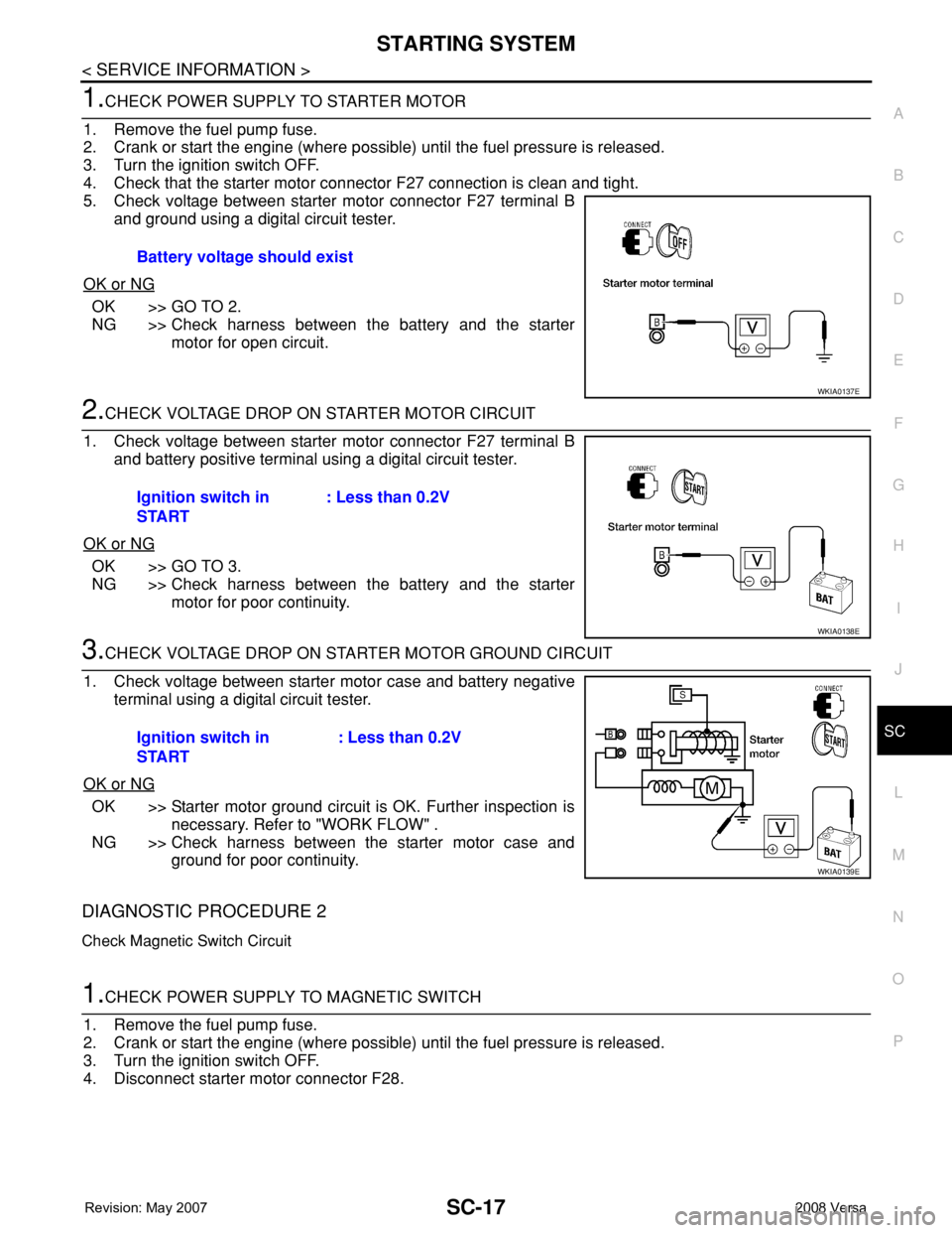
1.CHECK POWER SUPPLY TO STARTER MOTOR
1. Remove the fuel pump fuse.
2. Crank or start the engine (where possible) until the fuel pressure is released.
3. Turn the ignition switch OFF.
4. Check that the starter motor connector F27 connection is clean and tight.
5. Check voltage between starter motor connector F27 terminal B
and ground using a digital circuit tester.
OK or NG
OK >> GO TO 2.
NG >> Check harness between the battery and the starter
motor for open circuit.
2.CHECK VOLTAGE DROP ON STARTER MOTOR CIRCUIT
1. Check voltage between starter motor connector F27 terminal B
and battery positive terminal using a digital circuit tester.
OK or NG
OK >> GO TO 3.
NG >> Check harness between the battery and the starter
motor for poor continuity.
3.CHECK VOLTAGE DROP ON STARTER MOTOR GROUND CIRCUIT
1. Check voltage between starter motor case and battery negative
terminal using a digital circuit tester.
OK or NG
OK >> Starter motor ground circuit is OK. Further inspection is
necessary. Refer to "WORK FLOW" .
NG >> Check harness between the starter motor case and
ground for poor continuity.
DIAGNOSTIC PROCEDURE 2
Check Magnetic Switch Circuit
1.CHECK POWER SUPPLY TO MAGNETIC SWITCH
1. Remove the fuel pump fuse.
2. Crank or start the engine (where possible) until the fuel pressure is released.
3. Turn the ignition switch OFF.
4. Disconnect starter motor connector F28.Battery voltage should exist
WKIA0137E
Ignition switch in
START: Less than 0.2V
WKIA0138E
Ignition switch in
START: Less than 0.2V
WKIA0139E
Page 2600 of 2771
SC-18
< SERVICE INFORMATION >
STARTING SYSTEM
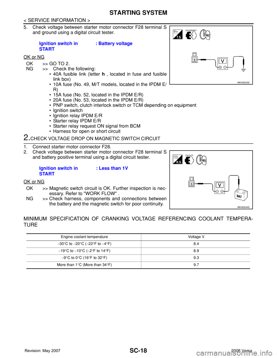
5. Check voltage between starter motor connector F28 terminal S
and ground using a digital circuit tester.
OK or NG
OK >> GO TO 2.
NG >> Check the following:
• 40A fusible link (letter h , located in fuse and fusible
link box)
• 10A fuse (No. 49, M/T models, located in the IPDM E/
R)
• 15A fuse (No. 52, located in the IPDM E/R)
• 20A fuse (No. 53, located in the IPDM E/R)
• PNP switch, clutch interlock switch or TCM depending on equipment
• Ignition switch
• Ignition relay IPDM E/R
• Starter relay IPDM E/R
• Starter relay request ON signal from BCM
• Harness for open or short circuit
2.CHECK VOLTAGE DROP ON MAGNETIC SWITCH CIRCUIT
1. Connect starter motor connector F28.
2. Check voltage between starter motor connector F28 terminal S
and battery positive terminal using a digital circuit tester.
OK or NG
OK >> Magnetic switch circuit is OK. Further inspection is nec-
essary. Refer to "WORK FLOW" .
NG >> Check harness, components and connections between
the battery and the magnetic switch for poor continuity.
MINIMUM SPECIFICATION OF CRANKING VOLTAGE REFERENCING COOLANT TEMPERA-
TURE
Ignition switch in
START: Battery voltage
WKIA5243E
Ignition switch in
START: Less than 1V
WKIA5244E
Engine coolant temperature Voltage V
−30°C to −20°C (−22°F to −4°F) 8.4
−19°C to −10°C (−2°F to 14°F) 8.9
−9°C to 0°C (16°F to 32°F) 9.3
More than 1°C (More than 34°F) 9.7