Page 2241 of 2771
LT-104
< SERVICE INFORMATION >
INTERIOR ROOM LAMP
Removal
1. Remove lens (1) and remove the room lamp by pulling down to
release the room lamp metal clips (A).
2. Disconnect connector and remove room lamp.
Installation
Installation is in the reverse order of removal.
PKIC1049E
Page 2252 of 2771
LU-2
< SERVICE INFORMATION >
PRECAUTIONS
SERVICE INFORMATION
PRECAUTIONS
Precaution for Supplemental Restraint System (SRS) "AIR BAG" and "SEAT BELT
PRE-TENSIONER"
INFOID:0000000001790697
The Supplemental Restraint System such as “AIR BAG” and “SEAT BELT PRE-TENSIONER”, used along
with a front seat belt, helps to reduce the risk or severity of injury to the driver and front passenger for certain
types of collision. This system includes seat belt switch inputs and dual stage front air bag modules. The SRS
system uses the seat belt switches to determine the front air bag deployment, and may only deploy one front
air bag, depending on the severity of a collision and whether the front occupants are belted or unbelted.
Information necessary to service the system safely is included in the SRS and SB section of this Service Man-
ual.
WARNING:
• To avoid rendering the SRS inoperative, which could increase the risk of personal injury or death in
the event of a collision which would result in air bag inflation, all maintenance must be performed by
an authorized NISSAN/INFINITI dealer.
• Improper maintenance, including incorrect removal and installation of the SRS, can lead to personal
injury caused by unintentional activation of the system. For removal of Spiral Cable and Air Bag
Module, see the SRS section.
• Do not use electrical test equipment on any circuit related to the SRS unless instructed to in this
Service Manual. SRS wiring harnesses can be identified by yellow and/or orange harnesses or har-
ness connectors.
Precaution for Liquid GasketINFOID:0000000001702514
LIQUID GASKET APPLICATION PROCEDURE
1. Remove old liquid gasket adhering to the liquid gasket application surface and the mating surface.
• Remove liquid gasket completely from the liquid gasket application surface, bolts, and bolt holes.
2. Wipe the liquid gasket application surface and the mating surface with white gasoline (lighting and heating
use) to remove adhering moisture, grease and foreign materials.
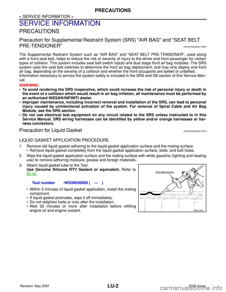
3. Attach liquid gasket tube to the Tool.
Use Genuine Silicone RTV Sealant or equivalent. Refer to
GI-42
.
• Within 5 minutes of liquid gasket application, install the mating
component.
• If liquid gasket protrudes, wipe it off immediately.
• Do not retighten bolts or nuts after the installation.
• Wait 30 minutes or more after installation before refilling
engine oil and engine coolant.Tool number :WS39930000 ( — )
PBIC2160E
Page 2256 of 2771
LU-6
< SERVICE INFORMATION >
ENGINE OIL
ENGINE OIL
InspectionINFOID:0000000001702518
ENGINE OIL LEVEL
NOTE:
Before starting engine, park vehicle on a level surface and check the engine oil level. If engine is already
started, stop it and allow 10 minutes before checking.
1. Pull out oil level gauge and wipe it clean.
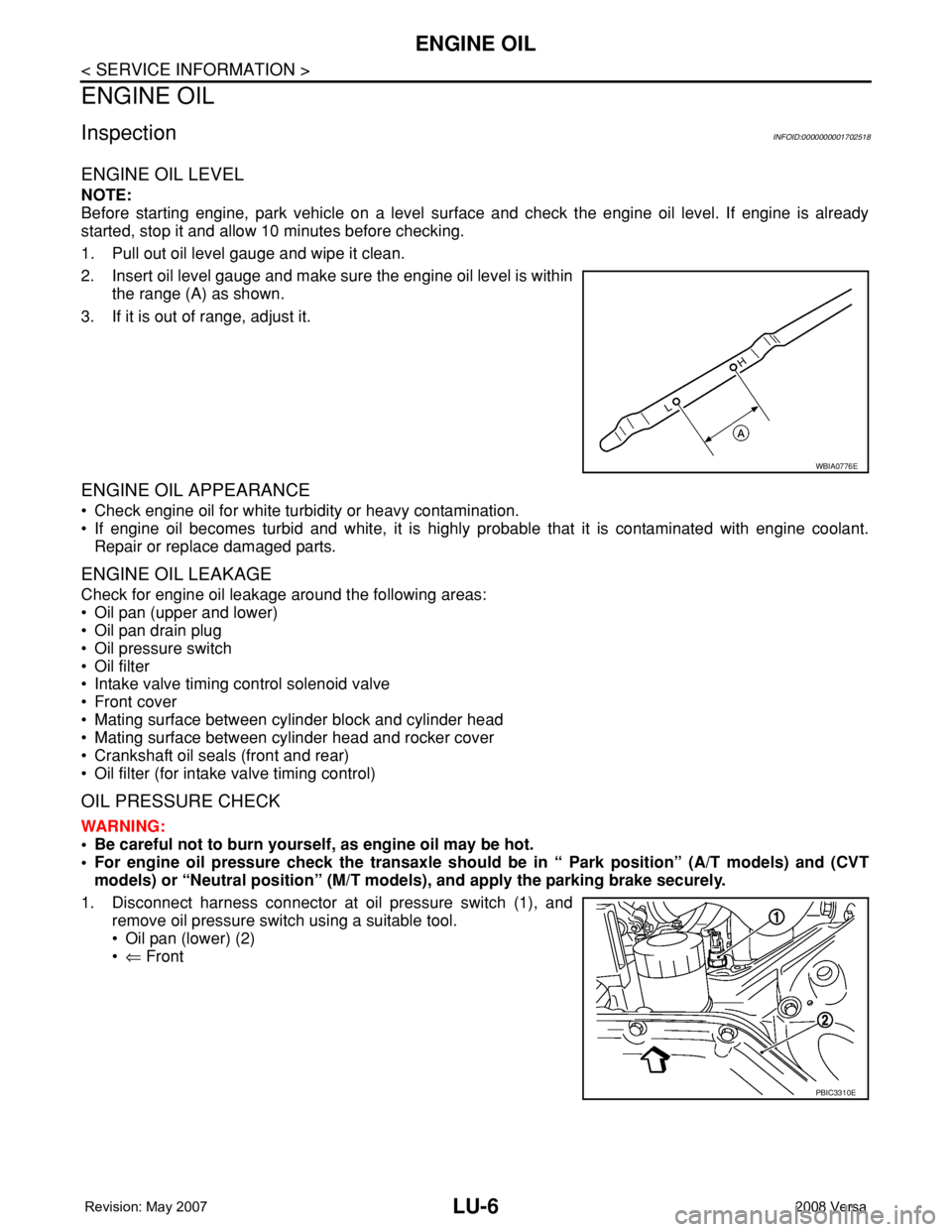
2. Insert oil level gauge and make sure the engine oil level is within
the range (A) as shown.
3. If it is out of range, adjust it.
ENGINE OIL APPEARANCE
• Check engine oil for white turbidity or heavy contamination.
• If engine oil becomes turbid and white, it is highly probable that it is contaminated with engine coolant.
Repair or replace damaged parts.
ENGINE OIL LEAKAGE
Check for engine oil leakage around the following areas:
• Oil pan (upper and lower)
• Oil pan drain plug
• Oil pressure switch
• Oil filter
• Intake valve timing control solenoid valve
• Front cover
• Mating surface between cylinder block and cylinder head
• Mating surface between cylinder head and rocker cover
• Crankshaft oil seals (front and rear)
• Oil filter (for intake valve timing control)
OIL PRESSURE CHECK
WARNING:
• Be careful not to burn yourself, as engine oil may be hot.
• For engine oil pressure check the transaxle should be in “ Park position” (A/T models) and (CVT
models) or “Neutral position” (M/T models), and apply the parking brake securely.
1. Disconnect harness connector at oil pressure switch (1), and
remove oil pressure switch using a suitable tool.
• Oil pan (lower) (2)
•⇐ Front
WBIA0776E
PBIC3310E
Page 2262 of 2771
MA-2
< SERVICE INFORMATION >
PRECAUTIONS
SERVICE INFORMATION
PRECAUTIONS
Precaution for Supplemental Restraint System (SRS) "AIR BAG" and "SEAT BELT
PRE-TENSIONER"
INFOID:0000000001704717
The Supplemental Restraint System such as “AIR BAG” and “SEAT BELT PRE-TENSIONER”, used along
with a front seat belt, helps to reduce the risk or severity of injury to the driver and front passenger for certain
types of collision. This system includes seat belt switch inputs and dual stage front air bag modules. The SRS
system uses the seat belt switches to determine the front air bag deployment, and may only deploy one front
air bag, depending on the severity of a collision and whether the front occupants are belted or unbelted.
Information necessary to service the system safely is included in the SR and SB section of this Service Man-
ual.
WARNING:
• To avoid rendering the SRS inoperative, which could increase the risk of personal injury or death in
the event of a collision which would result in air bag inflation, all maintenance must be performed by
an authorized NISSAN/INFINITI dealer.
• Improper maintenance, including incorrect removal and installation of the SRS, can lead to personal
injury caused by unintentional activation of the system. For removal of Spiral Cable and Air Bag
Module, see the SR section.
• Do not use electrical test equipment on any circuit related to the SRS unless instructed to in this
Service Manual. SRS wiring harnesses can be identified by yellow and/or orange harnesses or har-
ness connectors.
Page 2290 of 2771
MT-2
< SERVICE INFORMATION >
PRECAUTIONS
SERVICE INFORMATION
PRECAUTIONS
Precaution for Supplemental Restraint System (SRS) "AIR BAG" and "SEAT BELT
PRE-TENSIONER"
INFOID:0000000001703128
The Supplemental Restraint System such as “AIR BAG” and “SEAT BELT PRE-TENSIONER”, used along
with a front seat belt, helps to reduce the risk or severity of injury to the driver and front passenger for certain
types of collision. This system includes seat belt switch inputs and dual stage front air bag modules. The SRS
system uses the seat belt switches to determine the front air bag deployment, and may only deploy one front
air bag, depending on the severity of a collision and whether the front occupants are belted or unbelted.
Information necessary to service the system safely is included in the SRS and SB section of this Service Man-
ual.
WARNING:
• To avoid rendering the SRS inoperative, which could increase the risk of personal injury or death in
the event of a collision which would result in air bag inflation, all maintenance must be performed by
an authorized NISSAN/INFINITI dealer.
• Improper maintenance, including incorrect removal and installation of the SRS, can lead to personal
injury caused by unintentional activation of the system. For removal of Spiral Cable and Air Bag
Module, see the SRS section.
• Do not use electrical test equipment on any circuit related to the SRS unless instructed to in this
Service Manual. SRS wiring harnesses can be identified by yellow and/or orange harnesses or har-
ness connectors.
Precaution for Procedure without Cowl Top CoverINFOID:0000000001844076
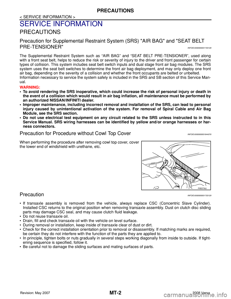
When performing the procedure after removing cowl top cover, cover
the lower end of windshield with urethane, etc.
PrecautionINFOID:0000000001703129
• If transaxle assembly is removed from the vehicle, always replace CSC (Concentric Slave Cylinder).
Installed CSC returns to the original position when removing transaxle assembly. Dust on clutch disc sliding
parts may damage CSC seal, and may cause clutch fluid leakage.
• Do not reuse transaxle oil.
• Drain, fill and check transaxle oil with the vehicle on level surface.
• During removal or installation, keep inside of transaxle clear of dust or dirt.
• Check for the correct installation orientation prior to removal or disassembly. If matching marks are required,
be certain they do not interfere with the function of the parts they are applied to.
• In principle, tighten bolts or nuts gradually in several steps working diagonally from inside to outside. If tight-
ening sequence is specified, follow it.
• Be careful not to damage the sliding surfaces and mating surfaces of parts.
PIIB3706J
Page 2303 of 2771
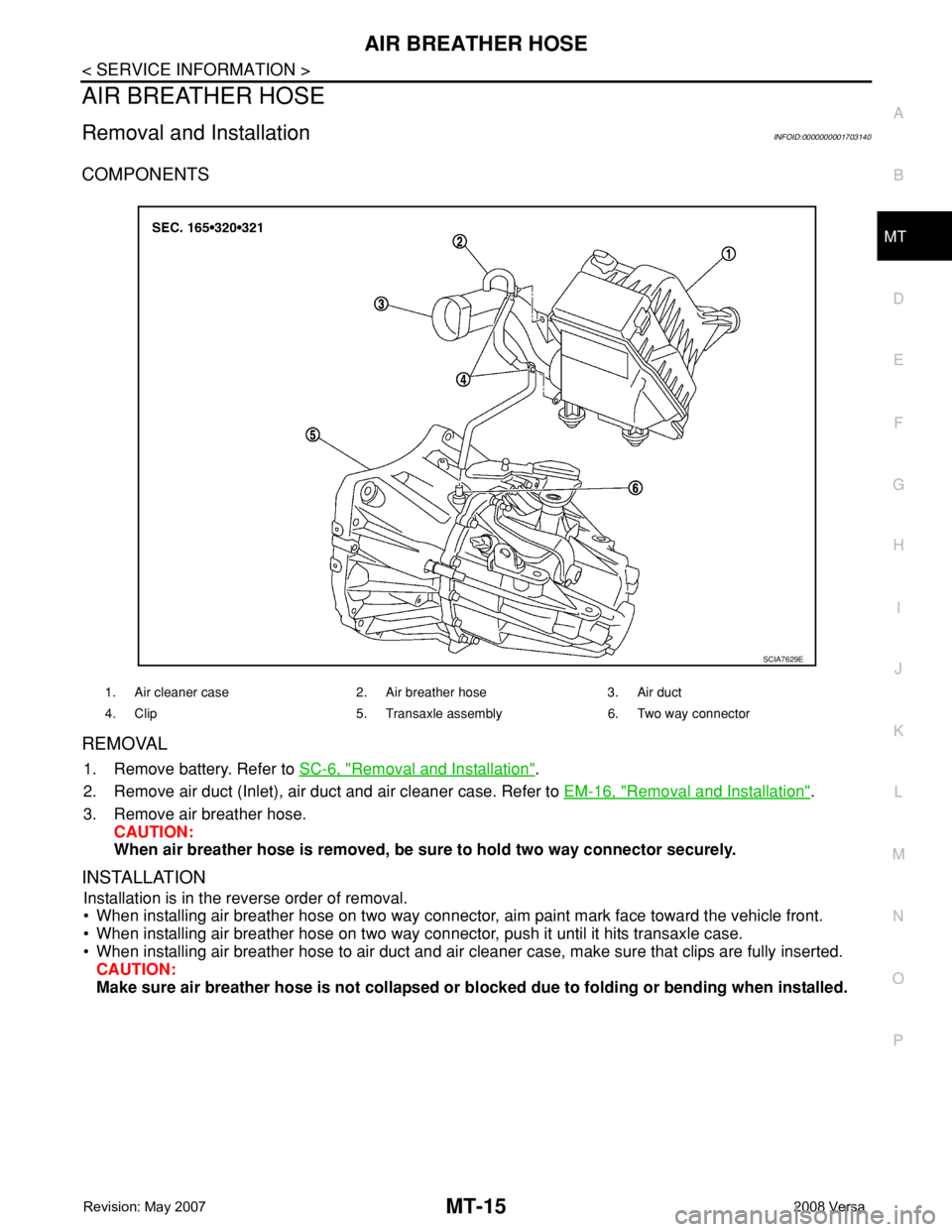
AIR BREATHER HOSE
MT-15
< SERVICE INFORMATION >
D
E
F
G
H
I
J
K
L
MA
B
MT
N
O
P
AIR BREATHER HOSE
Removal and InstallationINFOID:0000000001703140
COMPONENTS
REMOVAL
1. Remove battery. Refer to SC-6, "Removal and Installation".
2. Remove air duct (Inlet), air duct and air cleaner case. Refer to EM-16, "
Removal and Installation".
3. Remove air breather hose.
CAUTION:
When air breather hose is removed, be sure to hold two way connector securely.
INSTALLATION
Installation is in the reverse order of removal.
• When installing air breather hose on two way connector, aim paint mark face toward the vehicle front.
• When installing air breather hose on two way connector, push it until it hits transaxle case.
• When installing air breather hose to air duct and air cleaner case, make sure that clips are fully inserted.
CAUTION:
Make sure air breather hose is not collapsed or blocked due to folding or bending when installed.
1. Air cleaner case 2. Air breather hose 3. Air duct
4. Clip 5. Transaxle assembly 6. Two way connector
SCIA7629E
Page 2306 of 2771
MT-18
< SERVICE INFORMATION >
TRANSAXLE ASSEMBLY
Gear Components
1. Filler plug 2. Gasket 3. Transaxle case
4. Bushing 5. Shift finger 6. Snap ring
7. Oil gutter 8. Oil channel 9. Position switch
10. Shift lever oil seal 11. Shift lever 12. Retaining pin
13. Bracket 14. Differential side oil seal 15. Control lever oil seal
16. Control lever 17. Magnet 18. Drain plug
19. Input shaft oil seal 20. CSC (Concentric Slave Cylinder) 21. Clutch housing
22. Two way connector 23. Pinion shaft 24. Pinion gear
Apply Genuine Silicone RTV or the equivalent.
SFIA3291E
Page 2316 of 2771
MT-28
< SERVICE INFORMATION >
TRANSAXLE ASSEMBLY
31. Remove snap ring (1) and oil channel (2) from transaxle case.
32. Remove input shaft oil seal (1) from clutch housing using suit-
able tool.
33. Remove mainshaft front bearing outer race (1) and oil channel
(2) from clutch housing using Tool (A) and suitable tool (B).
34. Remove busings (1) from clutch housing using suitable tool.
35. Remove two way connector (1) from clutch housing.
PCIB1708E
PCIB1714E
Tool number : KV381054S0 (J-34286)
PCIB1718E
PCIB1717E
PCIB1720E