Page 1618 of 2771

EC-544
< SERVICE INFORMATION >
REFRIGERANT PRESSURE SENSOR
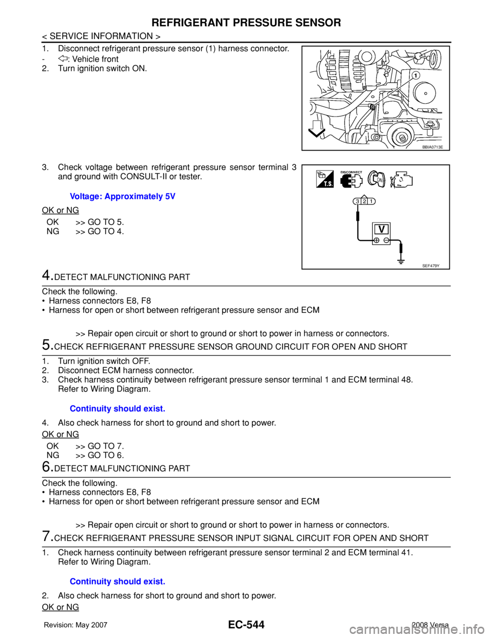
1. Disconnect refrigerant pressure sensor (1) harness connector.
- : Vehicle front
2. Turn ignition switch ON.
3. Check voltage between refrigerant pressure sensor terminal 3
and ground with CONSULT-II or tester.
OK or NG
OK >> GO TO 5.
NG >> GO TO 4.
4.DETECT MALFUNCTIONING PART
Check the following.
• Harness connectors E8, F8
• Harness for open or short between refrigerant pressure sensor and ECM
>> Repair open circuit or short to ground or short to power in harness or connectors.
5.CHECK REFRIGERANT PRESSURE SENSOR GROUND CIRCUIT FOR OPEN AND SHORT
1. Turn ignition switch OFF.
2. Disconnect ECM harness connector.
3. Check harness continuity between refrigerant pressure sensor terminal 1 and ECM terminal 48.
Refer to Wiring Diagram.
4. Also check harness for short to ground and short to power.
OK or NG
OK >> GO TO 7.
NG >> GO TO 6.
6.DETECT MALFUNCTIONING PART
Check the following.
• Harness connectors E8, F8
• Harness for open or short between refrigerant pressure sensor and ECM
>> Repair open circuit or short to ground or short to power in harness or connectors.
7.CHECK REFRIGERANT PRESSURE SENSOR INPUT SIGNAL CIRCUIT FOR OPEN AND SHORT
1. Check harness continuity between refrigerant pressure sensor terminal 2 and ECM terminal 41.
Refer to Wiring Diagram.
2. Also check harness for short to ground and short to power.
OK or NG
BBIA0713E
Voltage: Approximately 5V
SEF479Y
Continuity should exist.
Continuity should exist.
Page 1622 of 2771

EC-548
< SERVICE INFORMATION >
SERVICE DATA AND SPECIFICATIONS (SDS)
SERVICE DATA AND SPECIFICATIONS (SDS)
Fuel PressureINFOID:0000000001703081
Idle Speed and Ignition TimingINFOID:0000000001703082
*: Under the following conditions:
• Air conditioner switch: OFF
• Electric load: OFF (Lights, heater fan & rear window defogger)
• Steering wheel: Kept in straight-ahead position
Calculated Load ValueINFOID:0000000001703083
Mass Air Flow SensorINFOID:0000000001703084
*: Engine is warmed up to normal operating temperature and running under no load.
Intake Air Temperature SensorINFOID:0000000001703085
Engine Coolant Temperature SensorINFOID:0000000001703086
Fuel pressure at idle
Approximately 350 kPa (3.57 kg/cm2, 51 psi)
Target idle speedA/T No load* (in P or N position)
700 ± 50 rpm CVT No load* (In P or N position)
M/T No load* (in Neutral position)
Air conditioner: ONA/T In P or N position
850 rpm or more CVT In P or N position
M/T In Neutral position
Ignition timingA/T In P or N position
13 ± 5° BTDC CVT In P or N position
M/T In Neutral position
Calculated load value% (Using CONSULT-II or GST)
At idle10 - 35
At 2,500 rpm10 - 35
Supply voltageBattery voltage (11 - 14V)
Output voltage at idle1.0 - 1.3*V
Mass air flow (Using CONSULT-II or GST)1.0 - 4.0 g·m/sec at idle*
2.0 - 10.0 g·m/sec at 2,500 rpm*
Temperature °C (°F) Resistance kΩ
25 (77)1.800 - 2.200
Temperature °C (°F) Resistance kΩ
20 (68)2.1 - 2.9
50 (122)0.68 - 1.00
90 (194)0.236 - 0.260
Page 1626 of 2771

PRECAUTIONS
EI-3
< PRECAUTION >
C
D
E
F
G
H
J
K
L
MA
B
EI
N
O
P
PRECAUTION
PRECAUTIONS
Precaution for Supplemental Restraint System (SRS) "AIR BAG" and "SEAT BELT
PRE-TENSIONER"
INFOID:0000000001704210
The Supplemental Restraint System such as “AIR BAG” and “SEAT BELT PRE-TENSIONER”, used along
with a front seat belt, helps to reduce the risk or severity of injury to the driver and front passenger for certain
types of collision. This system includes seat belt switch inputs and dual stage front air bag modules. The SRS
system uses the seat belt switches to determine the front air bag deployment, and may only deploy one front
air bag, depending on the severity of a collision and whether the front occupants are belted or unbelted.
Information necessary to service the system safely is included in the SR and SB section of this Service Man-
ual.
WARNING:
• To avoid rendering the SRS inoperative, which could increase the risk of personal injury or death in
the event of a collision which would result in air bag inflation, all maintenance must be performed by
an authorized NISSAN/INFINITI dealer.
• Improper maintenance, including incorrect removal and installation of the SRS, can lead to personal
injury caused by unintentional activation of the system. For removal of Spiral Cable and Air Bag
Module, see the SR section.
• Do not use electrical test equipment on any circuit related to the SRS unless instructed to in this
Service Manual. SRS wiring harnesses can be identified by yellow and/or orange harnesses or har-
ness connectors.
PrecautionINFOID:0000000001704211
• When removing or disassembling any part, be careful not to damage or deform it. Protect parts which may
get in the way with cloth.
• When removing parts with a screwdriver or other tool, protect parts by wrapping them with vinyl or tape.
• Keep removed parts protected with cloth.
• If a clip is deformed or damaged, replace it.
• If an unreusable part is removed, replace it with a new one.
• Tighten bolts and nuts firmly to the specified torque.
• After re-assembly has been completed, make sure each part functions correctly.
• Remove stains in the following way.
- Water-soluble stains:
Dip a cloth in warm water, and squeeze tightly. After wiping the stain, wipe with a soft dry cloth.
- Oil stain:
Dissolve a synthetic detergent in warm water (density of 2 to 3% or less), dip the cloth, then clean off the
stain with the cloth. Next, dip the soft cloth in fresh water, and then squeeze it tightly. Then clean off the
detergent completely. Then wipe the area with a soft dry cloth.
• Do not use any organic solvent, such as thinner or benzine.
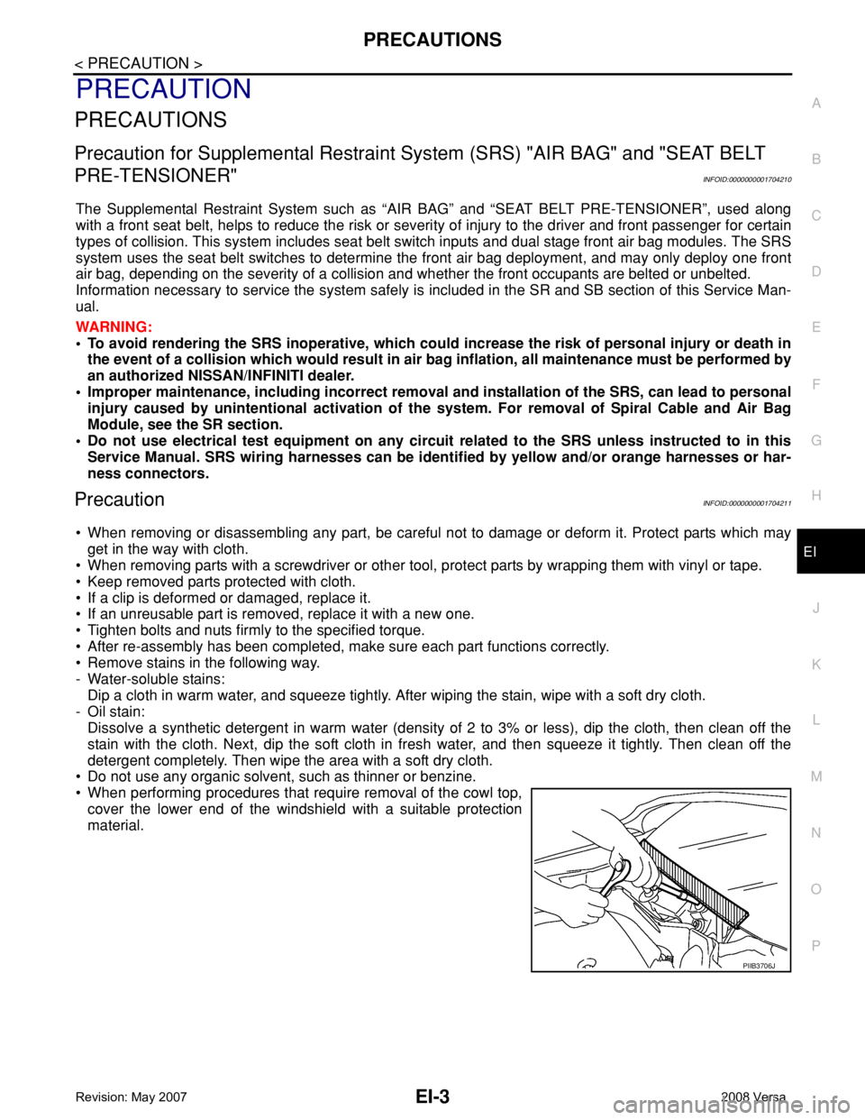
• When performing procedures that require removal of the cowl top,
cover the lower end of the windshield with a suitable protection
material.
PIIB3706J
Page 1653 of 2771
EI-30
< ON-VEHICLE REPAIR >
TRUNK LID FINISHER
TRUNK LID FINISHER
Removal and InstallationINFOID:0000000001704231
REMOVAL
1. Disconnect the negative and positive battery cables.
2. Open trunk lid, remove trunk lid finisher inner. Refer to EI-53
.
3. Remove trunk lid finisher outer nuts.
4. Release the clips, then pull trunk lid finisher outer away from trunk lid.
5. Disconnect trunk lid opener switch connector and trunk opener request switch connector, then remove
trunk lid finisher outer.
INSTALLATION
Installation is in the reverse order of removal.
1. Trunk lid finisher outer 2. Trunk lid opener switch connector 3. Trunk opener request switch connector
A. Clip C101
WIIA1413E
Page 1655 of 2771
EI-32
< ON-VEHICLE REPAIR >
DOOR FINISHER
DOOR FINISHER
Removal and InstallationINFOID:0000000001704233
FRONT DOOR
Removal
1. Open front door and front door window.
2. Disconnect the negative and positive battery cables.
3. Release the front door inside handle escutcheon pawls, then
slide the escutcheon rearward to remove from front door fin-
isher.
1. Power window and door lock/unlock
switch finisher2. Front door finisher 3. Inside handle escutcheon
Clip C101
LIIA2572E
PIIB6040E
Page 1656 of 2771
DOOR FINISHER
EI-33
< ON-VEHICLE REPAIR >
C
D
E
F
G
H
J
K
L
MA
B
EI
N
O
P
4. Insert a trim stick (A) or suitable tool into back edge of front door
power window and door lock/unlock switch finisher. Lift upward
to release the clips and remove.
5. Disconnect front door power window and door lock/unlock
switch harness connector.
6. Remove the (2) front door finisher screws.
7. Release the clips, then lift front door finisher upward to remove it
from door body panel.
Installation
Installation is in the reverse order of removal.
REAR DOOR
WIIA1237E
PIIB6042E
SIIA0810E
Page 1657 of 2771
EI-34
< ON-VEHICLE REPAIR >
DOOR FINISHER
Removal
1. Open rear door and rear door window.
2. Disconnect the negative and positive battery cables.
3. Release the rear door inside handle escutcheon pawls, then
slide the escutcheon rearward to remove from rear door finisher.
4. Insert a trim stick (A), or suitable tool into back edge of rear door
power window switch finisher. Lift upward to release the clips
and remove.
5. Disconnect rear door power window switch harness connector.
6. Remove rear door finisher screw.
1. Rear power window switch finisher 2. Rear door finisher 3. Inside handle escutcheon
Clip C101
LIIA2573E
PIIB6040E
WIIA1238E
Page 1680 of 2771

PRECAUTIONS
EM-3
< SERVICE INFORMATION >
C
D
E
F
G
H
I
J
K
L
MA
EM
N
P O
SERVICE INFORMATION
PRECAUTIONS
Precaution for Supplemental Restraint System (SRS) "AIR BAG" and "SEAT BELT
PRE-TENSIONER"
INFOID:0000000001702460
The Supplemental Restraint System such as “AIR BAG” and “SEAT BELT PRE-TENSIONER”, used along
with a front seat belt, helps to reduce the risk or severity of injury to the driver and front passenger for certain
types of collision. This system includes seat belt switch inputs and dual stage front air bag modules. The SRS
system uses the seat belt switches to determine the front air bag deployment, and may only deploy one front
air bag, depending on the severity of a collision and whether the front occupants are belted or unbelted.
Information necessary to service the system safely is included in the SRS and SB section of this Service Man-
ual.
WARNING:
• To avoid rendering the SRS inoperative, which could increase the risk of personal injury or death in
the event of a collision which would result in air bag inflation, all maintenance must be performed by
an authorized NISSAN/INFINITI dealer.
• Improper maintenance, including incorrect removal and installation of the SRS, can lead to personal
injury caused by unintentional activation of the system. For removal of Spiral Cable and Air Bag
Module, see the SRS section.
• Do not use electrical test equipment on any circuit related to the SRS unless instructed to in this
Service Manual. SRS wiring harnesses can be identified by yellow and/or orange harnesses or har-
ness connectors.
Precaution for Procedure without Cowl Top CoverINFOID:0000000001702461
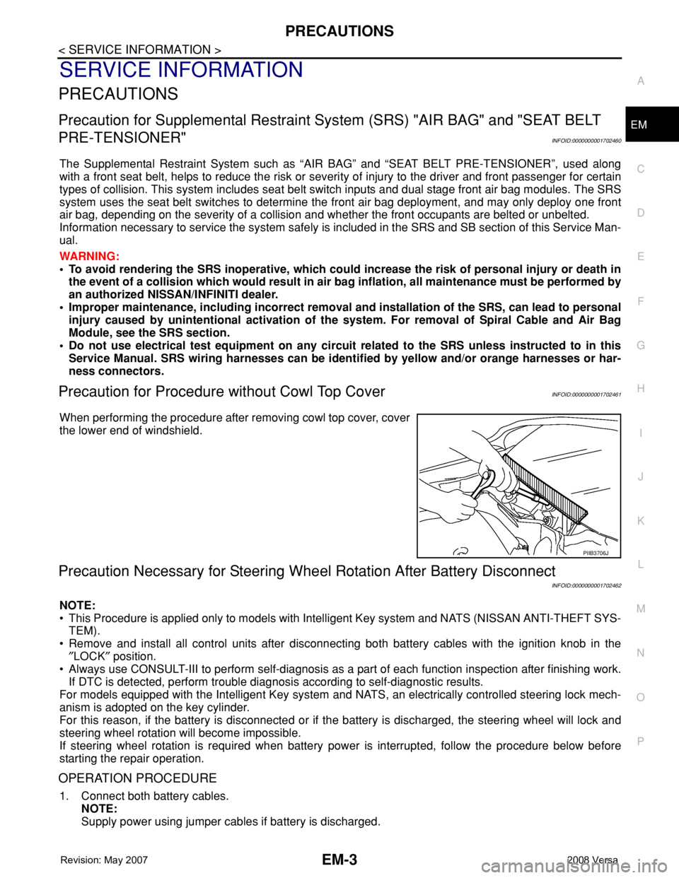
When performing the procedure after removing cowl top cover, cover
the lower end of windshield.
Precaution Necessary for Steering Wheel Rotation After Battery Disconnect
INFOID:0000000001702462
NOTE:
• This Procedure is applied only to models with Intelligent Key system and NATS (NISSAN ANTI-THEFT SYS-
TEM).
• Remove and install all control units after disconnecting both battery cables with the ignition knob in the
″LOCK″ position.
• Always use CONSULT-III to perform self-diagnosis as a part of each function inspection after finishing work.
If DTC is detected, perform trouble diagnosis according to self-diagnostic results.
For models equipped with the Intelligent Key system and NATS, an electrically controlled steering lock mech-
anism is adopted on the key cylinder.
For this reason, if the battery is disconnected or if the battery is discharged, the steering wheel will lock and
steering wheel rotation will become impossible.
If steering wheel rotation is required when battery power is interrupted, follow the procedure below before
starting the repair operation.
OPERATION PROCEDURE
1. Connect both battery cables.
NOTE:
Supply power using jumper cables if battery is discharged.
PIIB3706J