Page 1783 of 2771
EM-106
< SERVICE INFORMATION >
SERVICE DATA AND SPECIFICATIONS (SDS)
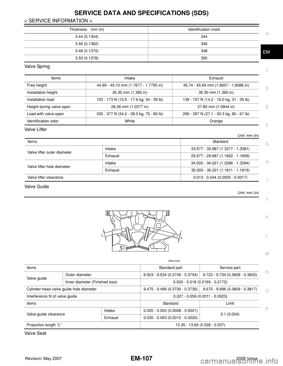
Valve Clearance
Unit: mm (in)
*: Approximately 80°C (176°F)
Available Valve Lifter
Valve stem diameter “d”Intake 5.465 - 5.480 (0.2152 - 0.2157)
Exhaust 5.455 - 5.470 (0.2148 - 0.2154)
Valve seat angle “α”45°15′ - 45°45′
Valve margin “T”Intake 1.1 (0.043)
Exhaust 1.2 (0.047)
Items Cold Hot* (reference data)
Intake 0.26 - 0.34 (0.010 - 0.013) 0.304 - 0.416 (0.012 - 0.016)
Exhaust 0.29 - 0.37 (0.011 - 0.015) 0.308 - 0.432 (0.012 - 0.017)
Thickness mm (in) Identification mark
3.00 (0.1181) 300
3.02 (0.1189) 302
3.04 (0.1197) 304
3.06 (0.1205) 306
3.08 (0.1213) 308
3.10 (0.1220) 310
3.12 (0.1228) 312
3.14 (0.1236) 314
3.16 (0.1244) 316
3.18 (0.1252) 318
3.20 (0.1260) 320
3.22 (0.1268) 322
3.24 (0.1276) 324
3.26 (0.1283) 326
3.28 (0.1291) 328
3.30 (0.1299) 330
3.32 (0.1307) 332
3.34 (0.1315) 334
3.36 (0.1323) 336
3.38 (0.1331) 338
3.40 (0.1339) 340
3.42 (0.1346) 342
KBIA0119E
Page 1784 of 2771

SERVICE DATA AND SPECIFICATIONS (SDS)
EM-107
< SERVICE INFORMATION >
C
D
E
F
G
H
I
J
K
L
MA
EM
N
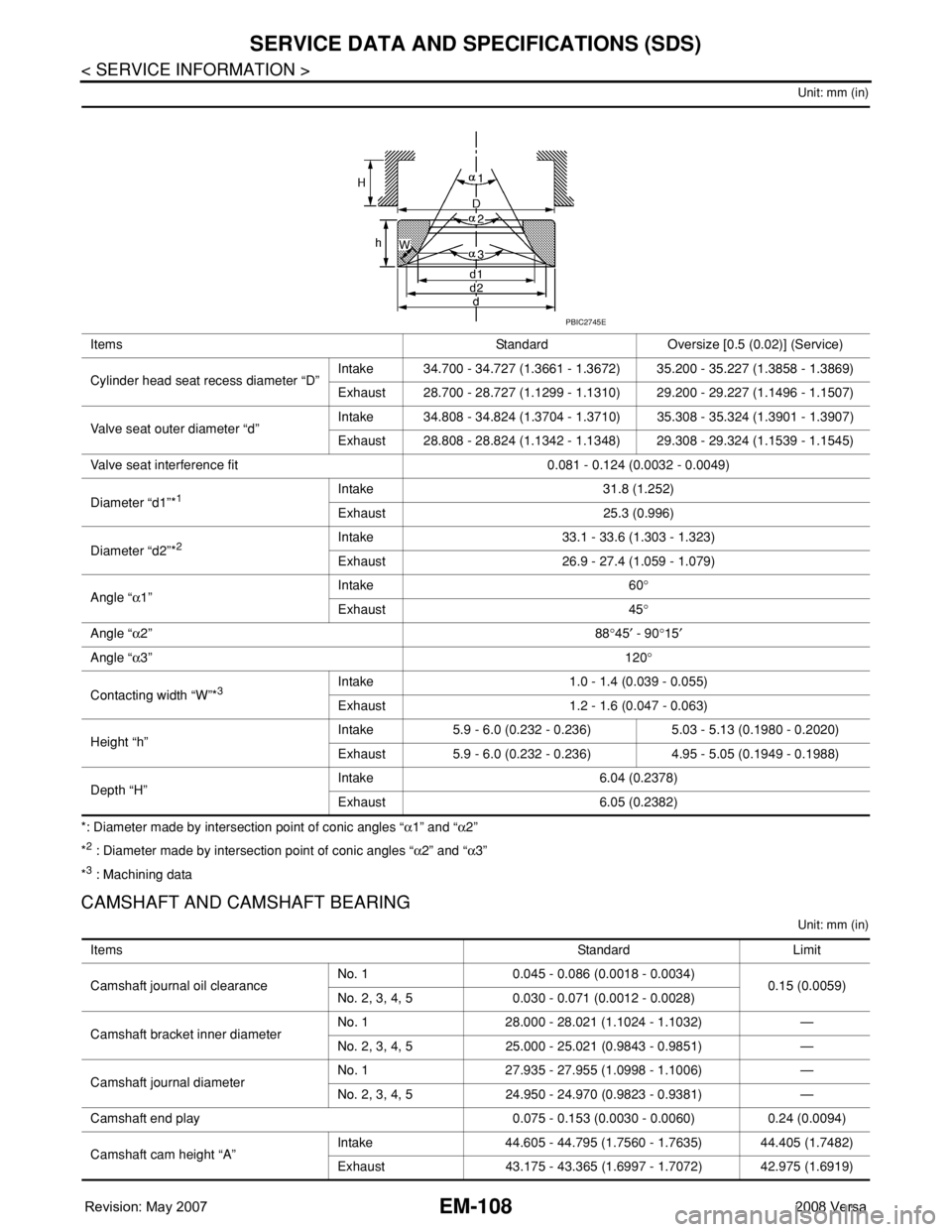
P O Va l v e Sp r i n g
Valve Lifter
Unit: mm (in)
Valve Guide
Unit: mm (in)
Valve Seat
3.44 (0.1354) 344
3.46 (0.1362) 346
3.48 (0.1370) 348
3.50 (0.1378) 350 Thickness mm (in) Identification mark
Items Intake Exhaust
Free height 44.90 - 45.10 mm (1.7677 - 1.7755 in) 45.74 - 45.94 mm (1.8007 - 1.8086 in)
Installation height 35.30 mm (1.390 in) 35.30 mm (1.390 in)
Installation load 153 - 173 N (15.6 - 17.6 kg, 34 - 39 lb) 139 - 157 N (14.2 - 16.0 kg, 31 - 35 lb)
Height during valve open 26.36 mm (1.0377 in) 27.80 mm (1.0944 in)
Load with valve open 335 - 377 N (34.2 - 38.5 kg, 75 - 85 lb) 266 - 297 N (27.1 - 30.3 kg, 60 - 67 lb)
Identification color White Orange
ItemsStandard
Valve lifter outer diameterIntake 33.977 - 33.987 (1.3377 - 1.3381)
Exhaust 29.977 - 29.987 (1.1802 - 1.1806)
Valve lifter hole diameterIntake 34.000 - 34.021 (1.3386 - 1.3394)
Exhaust 30.000 - 30.021 (1.1811 - 1.1819)
Valve lifter clearance0.013 - 0.044 (0.0005 - 0.0017)
Items Standard part Service part
Va l v e g u i d eOuter diameter 9.523 - 9.534 (0.3749 - 0.3754) 9.723 - 9.734 (0.3828 - 0.3832)
Inner diameter (Finished size) 5.500 - 5.518 (0.2165 - 0.2172)
Cylinder head valve guide hole diameter 9.475 - 9.496 (0.3730 - 0.3739) 9.675 - 9.696 (0.3809 - 0.3817)
Interference fit of valve guide 0.027 - 0.059 (0.0011 - 0.0023)
ItemsStandard Limit
Valve guide clearanceIntake 0.020 - 0.053 (0.0008 - 0.0021)
0.1 (0.004)
Exhaust 0.030 - 0.063 (0.0012 - 0.0025)
Projection length “L” 13.35 - 13.65 (0.526 - 0.537)
PBIC0184E
Page 1785 of 2771

EM-108
< SERVICE INFORMATION >
SERVICE DATA AND SPECIFICATIONS (SDS)
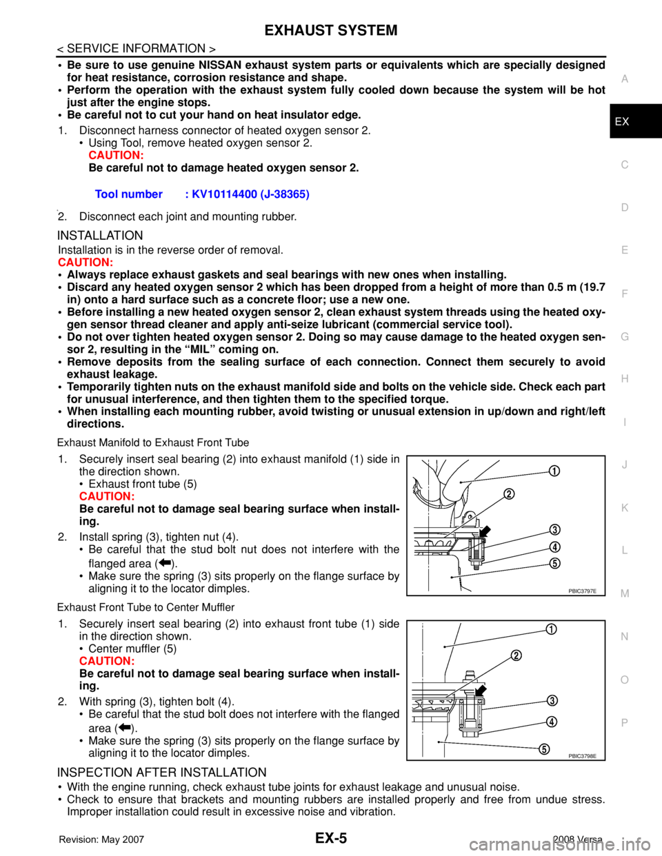
Unit: mm (in)
*: Diameter made by intersection point of conic angles “α1” and “α2”
*
2 : Diameter made by intersection point of conic angles “α2” and “α3”
*
3 : Machining data
CAMSHAFT AND CAMSHAFT BEARING
Unit: mm (in)
Items Standard Oversize [0.5 (0.02)] (Service)
Cylinder head seat recess diameter “D”Intake 34.700 - 34.727 (1.3661 - 1.3672) 35.200 - 35.227 (1.3858 - 1.3869)
Exhaust 28.700 - 28.727 (1.1299 - 1.1310) 29.200 - 29.227 (1.1496 - 1.1507)
Valve seat outer diameter “d”Intake 34.808 - 34.824 (1.3704 - 1.3710) 35.308 - 35.324 (1.3901 - 1.3907)
Exhaust 28.808 - 28.824 (1.1342 - 1.1348) 29.308 - 29.324 (1.1539 - 1.1545)
Valve seat interference fit 0.081 - 0.124 (0.0032 - 0.0049)
Diameter “d1”*
1Intake 31.8 (1.252)
Exhaust 25.3 (0.996)
Diameter “d2”*
2Intake 33.1 - 33.6 (1.303 - 1.323)
Exhaust 26.9 - 27.4 (1.059 - 1.079)
Angle “α1”Intake 60°
Exhaust 45°
Angle “α2”88°45′ - 90°15′
Angle “α3”120°
Contacting width “W”*
3Intake 1.0 - 1.4 (0.039 - 0.055)
Exhaust 1.2 - 1.6 (0.047 - 0.063)
Height “h”Intake 5.9 - 6.0 (0.232 - 0.236) 5.03 - 5.13 (0.1980 - 0.2020)
Exhaust 5.9 - 6.0 (0.232 - 0.236) 4.95 - 5.05 (0.1949 - 0.1988)
Depth “H”Intake 6.04 (0.2378)
Exhaust 6.05 (0.2382)
PBIC2745E
ItemsStandard Limit
Camshaft journal oil clearanceNo. 1 0.045 - 0.086 (0.0018 - 0.0034)
0.15 (0.0059)
No. 2, 3, 4, 5 0.030 - 0.071 (0.0012 - 0.0028)
Camshaft bracket inner diameterNo. 1 28.000 - 28.021 (1.1024 - 1.1032) —
No. 2, 3, 4, 5 25.000 - 25.021 (0.9843 - 0.9851) —
Camshaft journal diameterNo. 1 27.935 - 27.955 (1.0998 - 1.1006) —
No. 2, 3, 4, 5 24.950 - 24.970 (0.9823 - 0.9381) —
Camshaft end play 0.075 - 0.153 (0.0030 - 0.0060) 0.24 (0.0094)
Camshaft cam height “A”Intake 44.605 - 44.795 (1.7560 - 1.7635) 44.405 (1.7482)
Exhaust 43.175 - 43.365 (1.6997 - 1.7072) 42.975 (1.6919)
Page 1792 of 2771
EX-1
ENGINE
C
D
E
F
G
H
I
J
K
L
M
SECTION EX
A
EX
N
O
P
CONTENTS
EXHAUST SYSTEM
SERVICE INFORMATION ............................2
PRECAUTIONS ...................................................2
Precaution for Supplemental Restraint System
(SRS) "AIR BAG" and "SEAT BELT PRE-TEN-
SIONER" ...................................................................
2
PREPARATION ...................................................3
Special Service Tool .................................................3
Commercial Service Tool .........................................3
EXHAUST SYSTEM ...........................................4
Checking Exhaust System ........................................4
Component ...............................................................4
Removal and Installation ..........................................4
Page 1794 of 2771
PREPARATION
EX-3
< SERVICE INFORMATION >
C
D
E
F
G
H
I
J
K
L
MA
EX
N
P O
PREPARATION
Special Service ToolINFOID:0000000001703104
Commercial Service ToolINFOID:0000000001703105
Tool number
Tool nameDescription
KV10114400
(J-38365)
Heated oxygen sensor wrenchLoosening or tightening heated oxygen sen-
sor
a: 22 mm (0.87 in)
NT636
Tool nameDescription
Heated oxygen sensor thread cleaner Reconditioning the exhaust system threads
before installing a new heated oxygen sensor
(Use with anti-seize lubricant shown below.)
a: 18 mm (0.71 in) dia. for zirconia heated
oxygen sensor
b: 12 mm (0.47 in) dia. for titania heated ox-
ygen sensor
Anti-seize lubricant (Permatex 133AR
or equivalent meeting MIL specifica-
tion MIL-A-907)Lubricating heated oxygen sensor thread
cleaner when reconditioning exhaust system
threads
AEM488
AEM489
Page 1795 of 2771
EX-4
< SERVICE INFORMATION >
EXHAUST SYSTEM
EXHAUST SYSTEM
Checking Exhaust SystemINFOID:0000000001703106
Check exhaust pipes, muffler and mounting for improper attachment,
leaks, cracks, damage or deterioration.
• If necessary, repair or replace damaged parts.
ComponentINFOID:0000000001703107
Removal and InstallationINFOID:0000000001703108
REMOVAL
CAUTION:
SMA211A
1. Main muffler 2. Mounting rubber 3. Ring gasket
4. Center muffler 5. Mounting rubber 6. Spring
7. Seal bearing 8. Heated oxygen sensor 2 9. Exhaust front tube
10. Seal bearing 11. Stud bolt 12. Spring
13. Ground cable
WBIA0844E
Page 1796 of 2771

EXHAUST SYSTEM
EX-5
< SERVICE INFORMATION >
C
D
E
F
G
H
I
J
K
L
MA
EX
N
P O
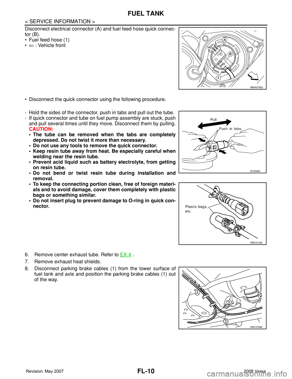
• Be sure to use genuine NISSAN exhaust system parts or equivalents which are specially designed
for heat resistance, corrosion resistance and shape.
• Perform the operation with the exhaust system fully cooled down because the system will be hot
just after the engine stops.
• Be careful not to cut your hand on heat insulator edge.
1. Disconnect harness connector of heated oxygen sensor 2.
• Using Tool, remove heated oxygen sensor 2.
CAUTION:
Be careful not to damage heated oxygen sensor 2.
a.2. Disconnect each joint and mounting rubber.
INSTALLATION
Installation is in the reverse order of removal.
CAUTION:
• Always replace exhaust gaskets and seal bearings with new ones when installing.
• Discard any heated oxygen sensor 2 which has been dropped from a height of more than 0.5 m (19.7
in) onto a hard surface such as a concrete floor; use a new one.
• Before installing a new heated oxygen sensor 2, clean exhaust system threads using the heated oxy-
gen sensor thread cleaner and apply anti-seize lubricant (commercial service tool).
• Do not over tighten heated oxygen sensor 2. Doing so may cause damage to the heated oxygen sen-
sor 2, resulting in the “MIL” coming on.
• Remove deposits from the sealing surface of each connection. Connect them securely to avoid
exhaust leakage.
• Temporarily tighten nuts on the exhaust manifold side and bolts on the vehicle side. Check each part
for unusual interference, and then tighten them to the specified torque.
• When installing each mounting rubber, avoid twisting or unusual extension in up/down and right/left
directions.
Exhaust Manifold to Exhaust Front Tube
1. Securely insert seal bearing (2) into exhaust manifold (1) side in
the direction shown.
• Exhaust front tube (5)
CAUTION:
Be careful not to damage seal bearing surface when install-
ing.
2. Install spring (3), tighten nut (4).
• Be careful that the stud bolt nut does not interfere with the
flanged area ( ).
• Make sure the spring (3) sits properly on the flange surface by
aligning it to the locator dimples.
Exhaust Front Tube to Center Muffler
1. Securely insert seal bearing (2) into exhaust front tube (1) side
in the direction shown.
• Center muffler (5)
CAUTION:
Be careful not to damage seal bearing surface when install-
ing.
2. With spring (3), tighten bolt (4).
• Be careful that the stud bolt does not interfere with the flanged
area ( ).
• Make sure the spring (3) sits properly on the flange surface by
aligning it to the locator dimples.
INSPECTION AFTER INSTALLATION
• With the engine running, check exhaust tube joints for exhaust leakage and unusual noise.
• Check to ensure that brackets and mounting rubbers are installed properly and free from undue stress.
Improper installation could result in excessive noise and vibration.Tool number : KV10114400 (J-38365)
PBIC3797E
PBIC3798E
Page 1830 of 2771

FL-10
< SERVICE INFORMATION >
FUEL TANK
Disconnect electrical connector (A) and fuel feed hose quick connec-
tor (B).
• Fuel feed hose (1)
•⇐ : Vehicle front
• Disconnect the quick connector using the following procedure.
- Hold the sides of the connector, push in tabs and pull out the tube.
- If quick connector and tube on fuel pump assembly are stuck, push
and pull several times until they move. Disconnect them by pulling.
CAUTION:
• The tube can be removed when the tabs are completely
depressed. Do not twist it more than necessary.
• Do not use any tools to remove the quick connector.
• Keep resin tube away from heat. Be especially careful when
welding near the resin tube.
• Prevent acid liquid such as battery electrolyte, from getting
on resin tube.
• Do not bend or twist resin tube during installation and
removal.
• To keep the connecting portion clean, free of foreign materi-
als and to avoid damage, cover them completely with plastic
bags or something similar.
• Do not insert plug to prevent damage to O-ring in quick con-
nector.
6. Remove center exhaust tube. Refer to EX-4
.
7. Remove exhaust heat shields.
8. Disconnect parking brake cables (1) from the lower surface of
fuel tank and axle and position the parking brake cables (1) out
of the way.
WBIA0782E
SFE562A
PBIC0163E
PBIC3786E