2008 NISSAN TIIDA exhaust
[x] Cancel search: exhaustPage 1678 of 2771
EM-1
ENGINE
C
D
E
F
G
H
I
J
K
L
M
SECTION EM
A
EM
N
O
P
CONTENTS
ENGINE MECHANICAL
SERVICE INFORMATION ............................3
PRECAUTIONS ...................................................3
Precaution for Supplemental Restraint System
(SRS) "AIR BAG" and "SEAT BELT PRE-TEN-
SIONER" ...................................................................
3
Precaution for Procedure without Cowl Top Cover ......3
Precaution Necessary for Steering Wheel Rota-
tion After Battery Disconnect .....................................
3
Precaution for Drain Coolant .....................................4
Precaution for Disconnecting Fuel Piping .................4
Precaution for Removal and Disassembly ................4
Precaution for Inspection, Repair and Replace-
ment ..........................................................................
4
Precaution for Assembly and Installation ..................4
Parts Requiring Angular Tightening ..........................4
Precaution for Liquid Gasket .....................................5
PREPARATION ...................................................7
Special Service Tool .................................................7
Commercial Service Tool ..........................................9
NOISE, VIBRATION AND HARSHNESS
(NVH) TROUBLESHOOTING ............................
11
NVH Troubleshooting - Engine Noise .....................11
Use the Chart Below to Help You Find the Cause
of the Symptom .......................................................
12
DRIVE BELTS ....................................................13
Component ..............................................................13
Checking Drive Belts ...............................................13
Tension Adjustment ................................................13
Removal and Installation .........................................13
Component ..............................................................14
Removal and Installation of Drive Belt Auto Ten-
sioner ......................................................................
14
AIR CLEANER AND AIR DUCT ........................16
Component ..............................................................16
Removal and Installation .........................................16
Changing Air Cleaner Filter .....................................17
INTAKE MANIFOLD .........................................18
Component ..............................................................18
Removal and Installation .........................................18
EXHAUST MANIFOLD ......................................21
Component ..............................................................21
Removal and Installation .........................................21
OIL PAN ............................................................24
Component ..............................................................24
Removal and Installation .........................................24
IGNITION COIL, SPARK PLUG AND ROCK-
ER COVER ........................................................
30
Component ..............................................................30
Removal and Installation .........................................30
FUEL INJECTOR AND FUEL TUBE ................33
Component ..............................................................33
Removal and Installation .........................................33
TIMING CHAIN ..................................................37
Component ..............................................................37
Removal and Installation .........................................38
CAMSHAFT .......................................................47
Component ..............................................................47
Removal and Installation .........................................47
Valve Clearance ......................................................55
OIL SEAL ..........................................................59
Removal and Installation of Valve Oil Seal ..............59
Removal and Installation of Front Oil Seal ..............59
Removal and Installation of Rear Oil Seal ...............60
CYLINDER HEAD .............................................62
On-Vehicle Service ..................................................62
Component ..............................................................63
Removal and Installation .........................................63
Component ..............................................................65
Disassembly and Assembly .....................................66
Inspection After Disassembly ..................................67
Page 1681 of 2771
EM-4
< SERVICE INFORMATION >
PRECAUTIONS
2. Use the Intelligent Key or mechanical key to turn the ignition switch to the ″ACC″ position. At this time, the
steering lock will be released.
3. Disconnect both battery cables. The steering lock will remain released and the steering wheel can be
rotated.
4. Perform the necessary repair operation.
5. When the repair work is completed, return the ignition switch to the ″LOCK″ position before connecting
the battery cables. (At this time, the steering lock mechanism will engage.)
6. Perform a self-diagnosis check of all control units using CONSULT-III.
Precaution for Drain CoolantINFOID:0000000001702463
• Drain coolant when engine is cooled.
Precaution for Disconnecting Fuel PipingINFOID:0000000001702464
• Before starting work, make sure no fire or spark producing items are in the work area.
• Release fuel pressure before disassembly.
• After disconnecting pipes, plug openings to stop fuel leakage.
Precaution for Removal and DisassemblyINFOID:0000000001702465
• When instructed to use special service tools, use the specified tools. Always be careful to work safely, avoid
forceful or uninstructed operations.
• Exercise maximum care to avoid damage to mating or sliding surfaces.
• Cover openings of engine system with tape or the equivalent, if necessary, to seal out foreign materials.
• Mark and arrange disassembly parts in an organized way for easy troubleshooting and assembly.
• When loosening nuts and bolts, as a basic rule, start with the one furthest outside, then the one diagonally
opposite, and so on. If the order of loosening is specified, do exactly as specified. Power tools may be used
where noted in the step.
Precaution for Inspection, Repair and ReplacementINFOID:0000000001702466
• Before repairing or replacing, thoroughly inspect parts. Inspect new replacement parts in the same way, and
replace if necessary.
Precaution for Assembly and InstallationINFOID:0000000001702467
• Use torque wrench to tighten bolts or nuts to specification.
• When tightening nuts and bolts, as a basic rule, equally tighten in several different steps starting with the
ones in center, then ones on inside and outside diagonally in this order. If the order of tightening is specified,
do exactly as specified.
• Replace with new gasket, packing, oil seal or O-ring.
• Thoroughly wash, clean, and air-blow each part. Carefully check oil or coolant passages for any restriction
and blockage.
• Avoid damaging sliding or mating surfaces. Completely remove foreign materials such as cloth lint or dust.
Before assembly, oil sliding surfaces well.
• Release air within route after draining coolant.
• Before starting engine, apply fuel pressure to fuel lines with turning ignition switch ON (with engine stopped).
Then make sure that there are no leaks at fuel line connections.
• After repairing, start engine and increase engine speed to check coolant, fuel, oil, and exhaust systems for
leakage.
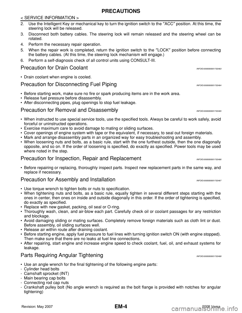
Parts Requiring Angular TighteningINFOID:0000000001702468
• Use an angle wrench for the final tightening of the following engine parts:
- Cylinder head bolts
- Camshaft sprocket (INT)
- Main bearing cap bolts
- Connecting rod cap nuts
- Crankshaft pulley bolt (No angle wrench is required as the bolt flange is provided with notches for angular
tightening)
Page 1687 of 2771
EM-10
< SERVICE INFORMATION >
PREPARATION
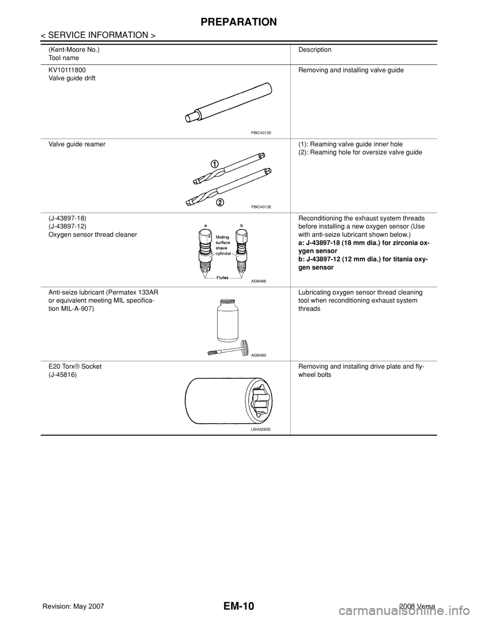
KV10111800
Valve guide driftRemoving and installing valve guide
Valve guide reamer (1): Reaming valve guide inner hole
(2): Reaming hole for oversize valve guide
(J-43897-18)
(J-43897-12)
Oxygen sensor thread cleanerReconditioning the exhaust system threads
before installing a new oxygen sensor (Use
with anti-seize lubricant shown below.)
a: J-43897-18 (18 mm dia.) for zirconia ox-
ygen sensor
b: J-43897-12 (12 mm dia.) for titania oxy-
gen sensor
Anti-seize lubricant (Permatex 133AR
or equivalent meeting MIL specifica-
tion MIL-A-907)Lubricating oxygen sensor thread cleaning
tool when reconditioning exhaust system
threads
E20 Torx® Socket
(J-45816)Removing and installing drive plate and fly-
wheel bolts (Kent-Moore No.)
Tool nameDescription
PBIC4012E
PBIC4013E
AEM488
AEM489
LBIA0285E
Page 1698 of 2771
EXHAUST MANIFOLD
EM-21
< SERVICE INFORMATION >
C
D
E
F
G
H
I
J
K
L
MA
EM
N
P O
EXHAUST MANIFOLD
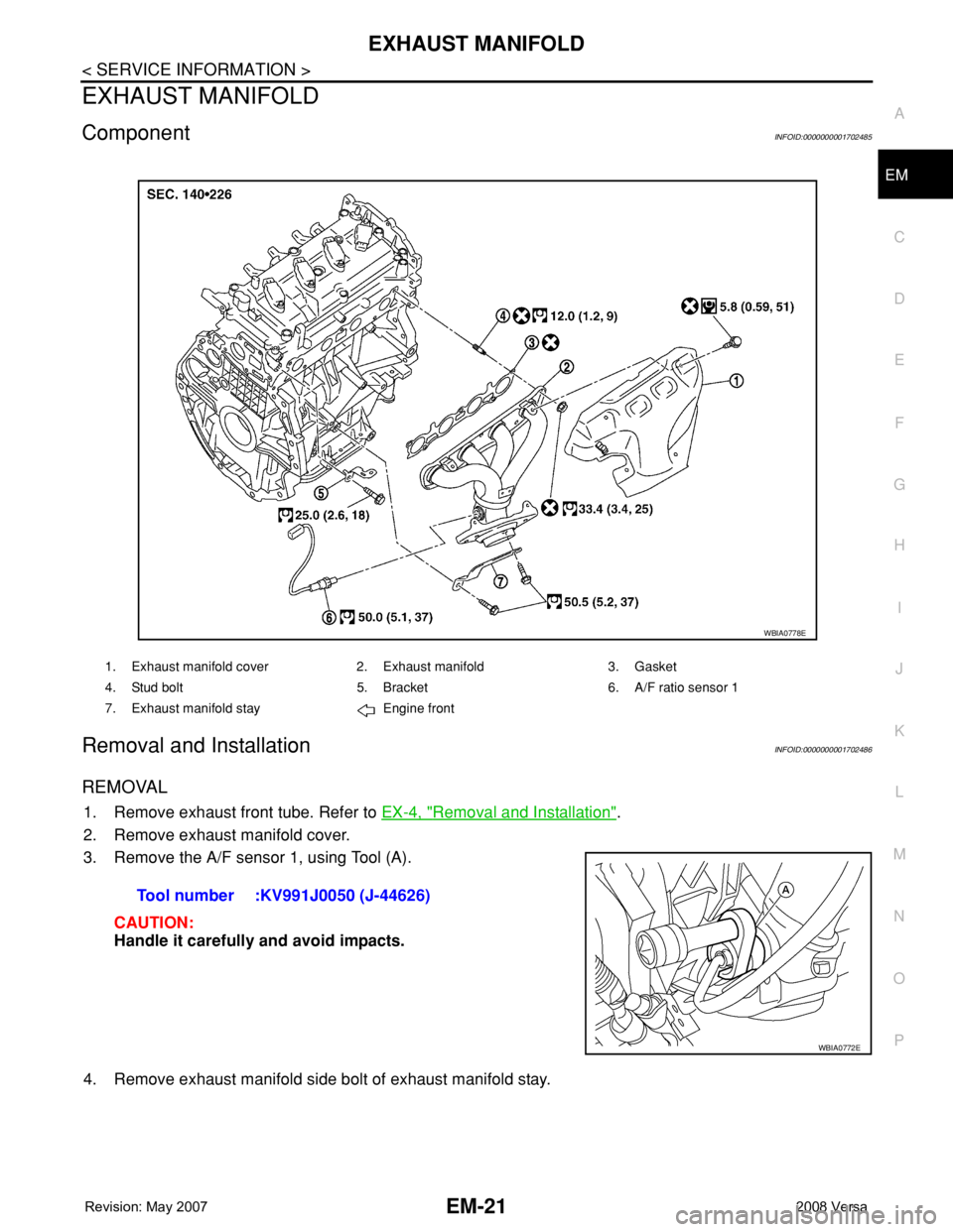
ComponentINFOID:0000000001702485
Removal and InstallationINFOID:0000000001702486
REMOVAL
1. Remove exhaust front tube. Refer to EX-4, "Removal and Installation".
2. Remove exhaust manifold cover.
3. Remove the A/F sensor 1, using Tool (A).
CAUTION:
Handle it carefully and avoid impacts.
4. Remove exhaust manifold side bolt of exhaust manifold stay.
1. Exhaust manifold cover 2. Exhaust manifold 3. Gasket
4. Stud bolt 5. Bracket 6. A/F ratio sensor 1
7. Exhaust manifold stay Engine front
WBIA0778E
Tool number :KV991J0050 (J-44626)
WBIA0772E
Page 1699 of 2771
EM-22
< SERVICE INFORMATION >
EXHAUST MANIFOLD
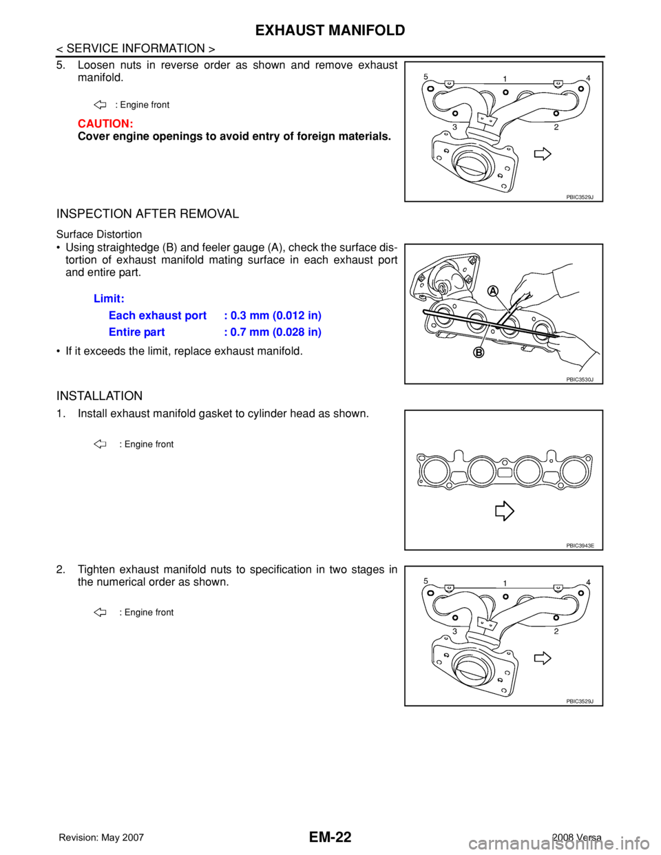
5. Loosen nuts in reverse order as shown and remove exhaust
manifold.
CAUTION:
Cover engine openings to avoid entry of foreign materials.
INSPECTION AFTER REMOVAL
Surface Distortion
• Using straightedge (B) and feeler gauge (A), check the surface dis-
tortion of exhaust manifold mating surface in each exhaust port
and entire part.
• If it exceeds the limit, replace exhaust manifold.
INSTALLATION
1. Install exhaust manifold gasket to cylinder head as shown.
2. Tighten exhaust manifold nuts to specification in two stages in
the numerical order as shown.
: Engine front
PBIC3529J
Limit:
Each exhaust port : 0.3 mm (0.012 in)
Entire part : 0.7 mm (0.028 in)
PBIC3530J
: Engine front
PBIC3943E
: Engine front
PBIC3529J
Page 1700 of 2771
EXHAUST MANIFOLD
EM-23
< SERVICE INFORMATION >
C
D
E
F
G
H
I
J
K
L
MA
EM
N
P O
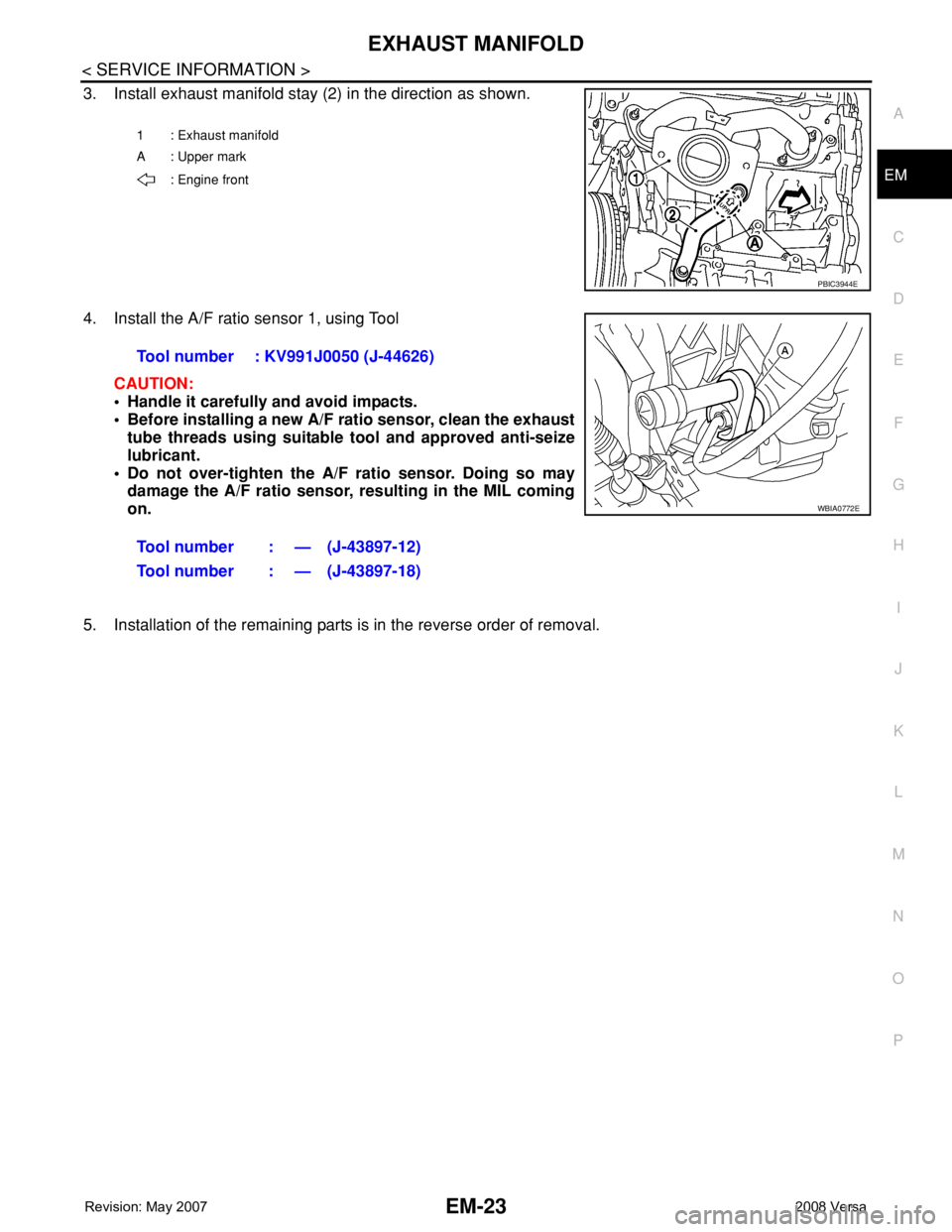
3. Install exhaust manifold stay (2) in the direction as shown.
4. Install the A/F ratio sensor 1, using Tool
CAUTION:
• Handle it carefully and avoid impacts.
• Before installing a new A/F ratio sensor, clean the exhaust
tube threads using suitable tool and approved anti-seize
lubricant.
• Do not over-tighten the A/F ratio sensor. Doing so may
damage the A/F ratio sensor, resulting in the MIL coming
on.
5. Installation of the remaining parts is in the reverse order of removal.
1 : Exhaust manifold
A : Upper mark
: Engine front
PBIC3944E
Tool number : KV991J0050 (J-44626)
Tool number : — (J-43897-12)
Tool number : — (J-43897-18)
WBIA0772E
Page 1726 of 2771
CAMSHAFT
EM-49
< SERVICE INFORMATION >
C
D
E
F
G
H
I
J
K
L
MA
EM
N
P O
13. Remove valve lifters.
NOTE:
Identify installed positions, and store them without mixing them up.
INSPECTION AFTER REMOVAL
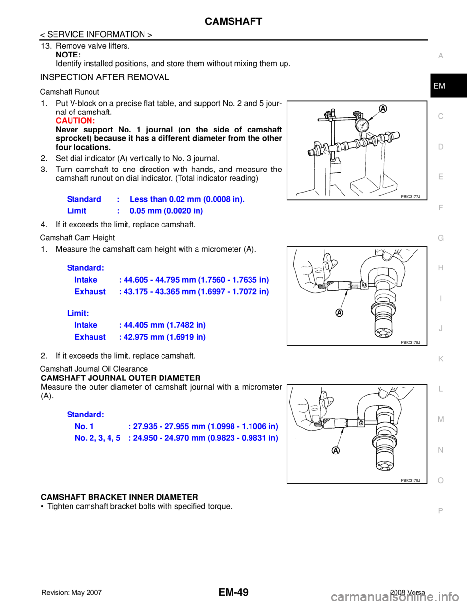
Camshaft Runout
1. Put V-block on a precise flat table, and support No. 2 and 5 jour-
nal of camshaft.
CAUTION:
Never support No. 1 journal (on the side of camshaft
sprocket) because it has a different diameter from the other
four locations.
2. Set dial indicator (A) vertically to No. 3 journal.
3. Turn camshaft to one direction with hands, and measure the
camshaft runout on dial indicator. (Total indicator reading)
4. If it exceeds the limit, replace camshaft.
Camshaft Cam Height
1. Measure the camshaft cam height with a micrometer (A).
2. If it exceeds the limit, replace camshaft.
Camshaft Journal Oil Clearance
CAMSHAFT JOURNAL OUTER DIAMETER
Measure the outer diameter of camshaft journal with a micrometer
(A).
CAMSHAFT BRACKET INNER DIAMETER
• Tighten camshaft bracket bolts with specified torque. Standard : Less than 0.02 mm (0.0008 in).
Limit : 0.05 mm (0.0020 in)
PBIC3177J
Standard:
Intake : 44.605 - 44.795 mm (1.7560 - 1.7635 in)
Exhaust : 43.175 - 43.365 mm (1.6997 - 1.7072 in)
Limit:
Intake : 44.405 mm (1.7482 in)
Exhaust : 42.975 mm (1.6919 in)
PBIC3178J
Standard:
No. 1 : 27.935 - 27.955 mm (1.0998 - 1.1006 in)
No. 2, 3, 4, 5 : 24.950 - 24.970 mm (0.9823 - 0.9831 in)
PBIC3179J
Page 1728 of 2771
CAMSHAFT
EM-51
< SERVICE INFORMATION >
C
D
E
F
G
H
I
J
K
L
MA
EM
N
P O
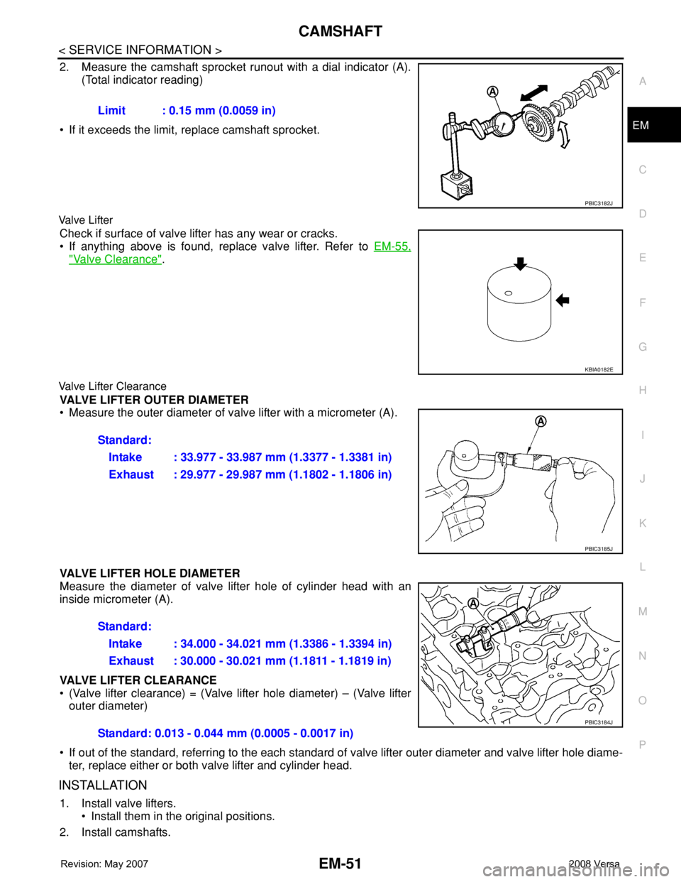
2. Measure the camshaft sprocket runout with a dial indicator (A).
(Total indicator reading)
• If it exceeds the limit, replace camshaft sprocket.
Valve Lifter
Check if surface of valve lifter has any wear or cracks.
• If anything above is found, replace valve lifter. Refer to EM-55,
"Valve Clearance".
Valve Lifter Clearance
VALVE LIFTER OUTER DIAMETER
• Measure the outer diameter of valve lifter with a micrometer (A).
VALVE LIFTER HOLE DIAMETER
Measure the diameter of valve lifter hole of cylinder head with an
inside micrometer (A).
VALVE LIFTER CLEARANCE
• (Valve lifter clearance) = (Valve lifter hole diameter) – (Valve lifter
outer diameter)
• If out of the standard, referring to the each standard of valve lifter outer diameter and valve lifter hole diame-
ter, replace either or both valve lifter and cylinder head.
INSTALLATION
1. Install valve lifters.
• Install them in the original positions.
2. Install camshafts.Limit : 0.15 mm (0.0059 in)
PBIC3182J
KBIA0182E
Standard:
Intake : 33.977 - 33.987 mm (1.3377 - 1.3381 in)
Exhaust : 29.977 - 29.987 mm (1.1802 - 1.1806 in)
PBIC3185J
Standard:
Intake : 34.000 - 34.021 mm (1.3386 - 1.3394 in)
Exhaust : 30.000 - 30.021 mm (1.1811 - 1.1819 in)
Standard: 0.013 - 0.044 mm (0.0005 - 0.0017 in)
PBIC3184J